

Page 1

CIO-SSH16
USER’S MANUAL
Revision 3
October, 2000
Page 2

MEGA-FIFO, the CIO prefix to data acquisition board model numbers, the PCM prefix to data
acquisition board model numbers, PCM-DAS08, PCM-D24C3, PCM-DAC02, PCM-COM422,
PCM-COM485, PCM-DMM, PCM-DAS16D/12, PCM-DAS16S/12, PCM-DAS16D/16,
PCM-DAS16S/16, PCI-DAS6402/16, Universal Library, InstaCal, Harsh Environment
Warranty and Measurement Computing Corporatio n are registered trademarks of Measurement
Computing Corporation.
IBM, PC, and PC/AT are trademarks of International Business Machines Corp. Windows is a
trademark of Microsoft Corp. All other trademarks are the property of their respective owners.
Information furnished by Measurement Computing Corp. is believed to be accurate and
reliable. However, no responsibility is assumed by Measurement Computing Corporation
neither for its use; nor for any infringements of patents or other rights of third parties, which
may result from its use. No license is granted by implication or otherwise under any patent or
copyrights of Measurement Computing Corporation.
All rights reserved. No part of this publication may be reproduced, stored in a retrieval system,
or transmitted, in any form by any means, electronic, mechanical, by photocopying, recording
or otherwise without the prior written permission of Measurement Computing Corporation.
Notice
Measurement Computing Corporation does not authorize any
Measurement Computing Corporation product for use in life support
systems and/or devices without the written approval of the President of
Measurement Computing Corporation Life support devices/systems are
devices or systems which, a) are intended for surgical implantation into
the body, or b) support or sustain life and whose failure to perform can
be reasonably expected to result in injury. Measurement Computing
Corp. products are not designed with the components required, and are
not subject to the testing required to ensure a level of reliability suitable
for the treatment and diagnosis of people.
(C) Copyright 2000
HM CIO-SSH16.lwp
Measurement Computing Corp.
Page 3

1.0 SOFTWARE INSTALLATION .....................................
2.0 HARDWARE INSTALLATION ..................................
3.0 SIGNAL CONNECTION ..........................................
4.0 ARCHITECTURE ................................................
5.0 SPECIFICATIONS ..............................................
6.0 ANALOG ELECTRONICS .......................................
1
1
12.1 INTRODUCTION ..............................................
22.2 POWER CABLE ...............................................
32.3 SIGNAL CABLE ...............................................
42.4 ANALOG INPUT BOARD SETUP .................................
42.5 GAIN SWITCHES ..............................................
5
53.1 CONNECTOR DIAGRAM .......................................
53.2 ANALOG INPUTS .............................................
53.3 FLOATING DIFFERENTIAL .....................................
63.4 DIFFERENTIAL ...............................................
8
84.1 ANALOG INPUT ...............................................
84.2 AMPLIFICATION ..............................................
94.3 CIO-SSH16 vs. PROGRAMMABLE GAIN A/D BOARDS ..............
104.4 SAMPLE & HOLD ............................................
124.5 DROOP RATE ................................................
134.6 ADDING AMPLIFIERS & SAMPLE / HOLD CHIPS .................
14
16
166.1 VOLTAGE DIVIDERS .........................................
186.2 DIFFERENTIAL & SINGLE ENDED INPUTS ......................
206.3 COMMON MISUNDERSTANDINGS .............................
206.4 GROUND LOOPS ............................................
206.5 LOW PASS FILTERS ..........................................
216.6 A/D RESOLUTION & ENGINEERING UNITS ......................
226.7 ENGINEERING UNITS ........................................
226.8 CURRENT LOOP (4-20 mA) ....................................
236.9 NOISE ......................................................
Page 4

This page is blank.
Page 5
1.0 SOFTWARE INSTALLATION
Before installing the board, install and run InstaCal. This package is the installation,
calibration and test utility included with your board. InstaCal will guide you through
switch and jumper settings for your board. Detailed information regarding these
settings can be found below. Refer to the Extended Software Installation Manual for
InstaCal installation instructions.
2.0 HARDWARE INSTALLATION
2.1 INTRODUCTION
The CIO-SSH16 is a signal conditioning accessory board designed to improve the
performance of a multi-channel analog input board (such as the CIO-DAS16)
wherever channel to channel skew must be minimized. The CIO-SSH16 is shipped
with four channels installed but components for additional channels can be purchased
for up to 16 channels of signal conditioning. As an accessory, it is mounted external
to the PC. It may be placed in the open on your bench top or in a case.
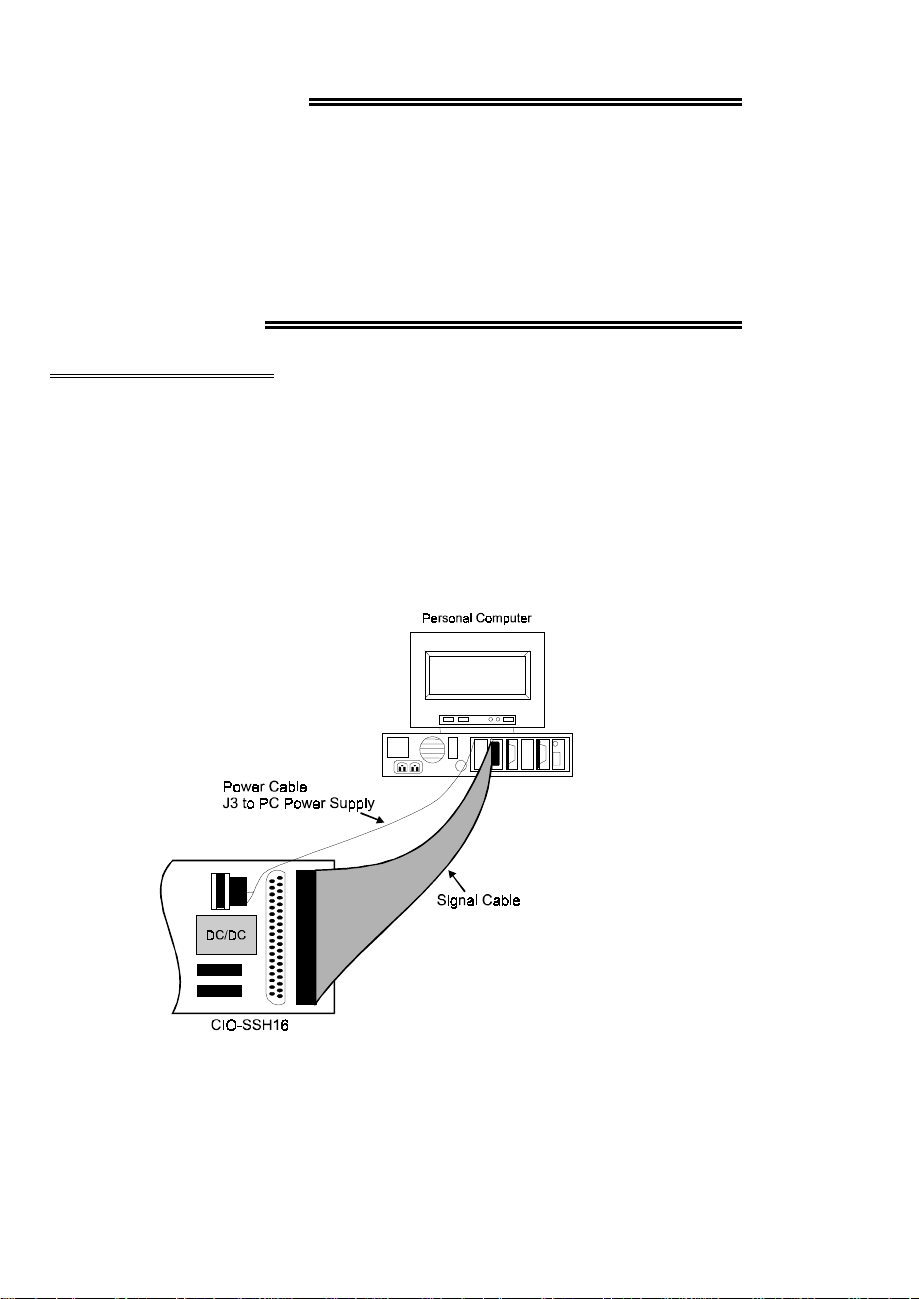
P18 to Analog Input Board
Figure 2-1. Board Cabling
1
Page 6

There are two cables used with CIO-SSH16; a signal cable and a power cable. The
power cable (C-PCPOWER-10) is supplied with the CIO-SSH16.
The power cable is black with two white MOLEX connectors. One end mates with
the J3 connector on the SSH16 and the other mates with any one of the available PC
power expansion plugs inside the PC.
The signal cable (C37FF-# or C37FFS-#) is a 37-conductor cable with 37D female
connectors at each end. One end plugs into the P18 connector of the CIO-SSH16, the
other plugs into the analog connector of a compatible analog input board (such as the
CIO-DAS16). (Figure 2-1).
2.2 POWER CABLE
A separate power cable is required because the CIO-SSH16 draws 1 amp from the
+5V supply to power the chips and the DC/DC converter which supplies the analog
components with +/-15V. This is more current than the C37FF cable should carry.
The C-PCPOWER-10 cable included with the CIO-SSH16 provides ample current
carrying capability.
The C-PCPOWER-10 power cable has two connectors, one male and one female.
The male end has metal pins, the female end, metal sockets.
The male connector will mate with any of the unused PC power expansion plugs
inside your PC. It is likely that there are unused plugs attac hed to wires which come
from the PC power supply on your PC. If not, order the C-PCPOWER-Y adapter to
add another connection. Plug the male end of the C-PCPOWER-10 power cable into
one of the unused power connectors.
Run the C-PCPOWER-10 power cable out the back of the PC. Use an expansion slot
or other orifice. If you prefer a connection external to the PC, the BP-POWER
adapter is available to bring the power connector out to a bracket that mounts in an
unused expansion slot.
WARNING
Use care so that the C-PCPOWER-10 power cable is not pinched by
the PC case. If the cable were severed, a serious short circuit would
result, possibly damaging your computer.
Power to the SSH 16 is supplied via a four pin MOLEX connector. This connector is
the exact mate of the standard PC Power supply expansion power connector. The
expansion power connectors are located inside the PC and carry +5V, +12V and
Ground. They are used primarily for disk drive power, but, there are more power
expansion connectors than you are likely to use (Figure 4-2) .
2
Page 7
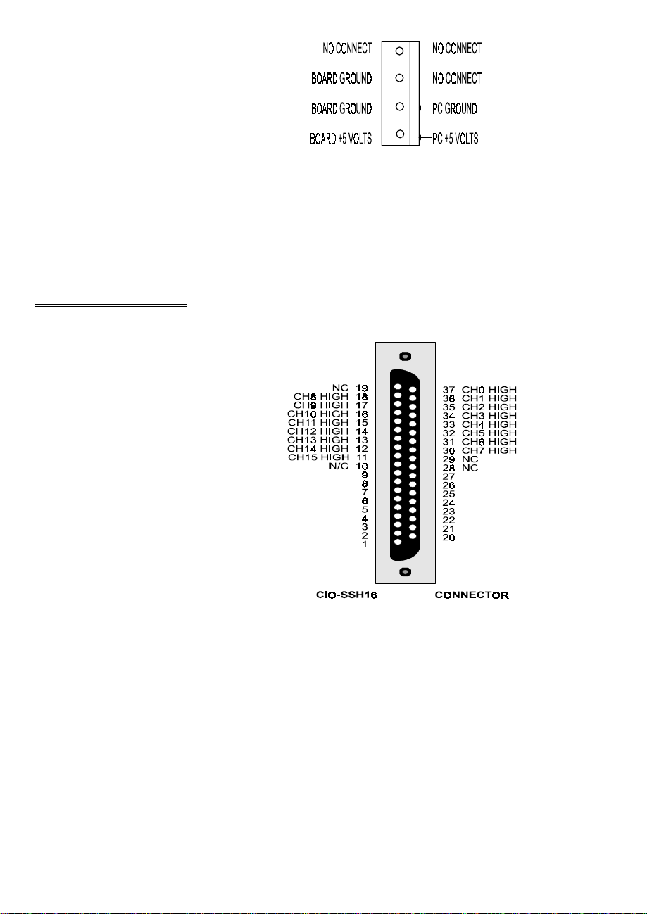
The SSH16 requires 1 Amp of +5 volt power.
You may supply this power from the PC, as we
recommend, using the cable supplied, or you
may use an alternate power supply.
Figure 4-2. Power Connector
Caution on using alternate power supplies: The analog interface from the SSH-16 to
the CIO-DAS16 is a single ended voltage signal connection. As such, it is will not
reject errors induced by a potential difference between the PC power supply and the
alternate supply you use to power the SSH16. Please be certain the PC power supply
and alternate power supply share a common ground.
2.3 SIGNAL CABLE
The CIO-SSH16 signal connector is nearly
a mirror of the CIO-DAS16 signal cable in
16 channel mode (Figure 1-2). There are
two 37D connectors on the CIO-SSH16
wired in parallel. The second, P19, permits
daisy chaining signals to other signal
conditioning or screw terminal boards.
Use any 37 conductor ribbon cable with
female D-37 connectors to connect a
CIO-SSH16 to a CIO-DAS16 or other
compatible analog input board. The cable
length should not exceed 10 feet.
P14, DA0
N/C
P14, GND
P14, IP1
P14, IP3
P13, OP1
P13, OP3
P13, OUT0
P13, +5V
P16, DA1O
P16, S/H
P16, IP0
P16, IP2
P15, OP0
P15, OP2
P15, CLK1
P15, OUT2
Connect one end of the signal cable to the
P18 & P19
analog input boards analog connector and
the other to the CIO-SSH16 P18 connector. Figure 1-2 Signal Connector Pin-out
A shielded cable (C37FFS-#) is preferable if EMI or RMI is present with sufficient
energy to interfere with noise free measurements. The connection between the
CIO-SSH16 and the analog input board is single ended so signals on the cable have no
common mode noise rejection.
The signals labeled P13, P14, P15 & P16 (Figure 1-2) correspond to the four screw
terminal blocks where o ther signals co ming from or going to your A/D boa rd may be
3
Page 8
connected. The nomenclature on the CIO-SSH16 corresponds to CIO-DAS16 signals.
2.4 ANALOG INPUT BOARD SETUP
The analog input board must be configured for single-ended input. If the board you
are using with the CIO-SSH16 supports both 8 channel differential and 16 channel
single-ended configurations, set the board to 16 channels single-ended.
You may also need to configure a jumper on the analog input board to supply the
sample-hold signal to the CIO-SSH16. The SSH16 must have a SAMPLE / HOLD
signal in order to trigger the LF398 sample & hold chips. The LF398s sample the
input signal on each channel when the analog input board samples channel 0 and each
channels signal is held until the next time channel 0 is sampled.
Refer to the users manual for the analog input board you are using for details
regarding configuration of the analog input and the sample / hold signal output.
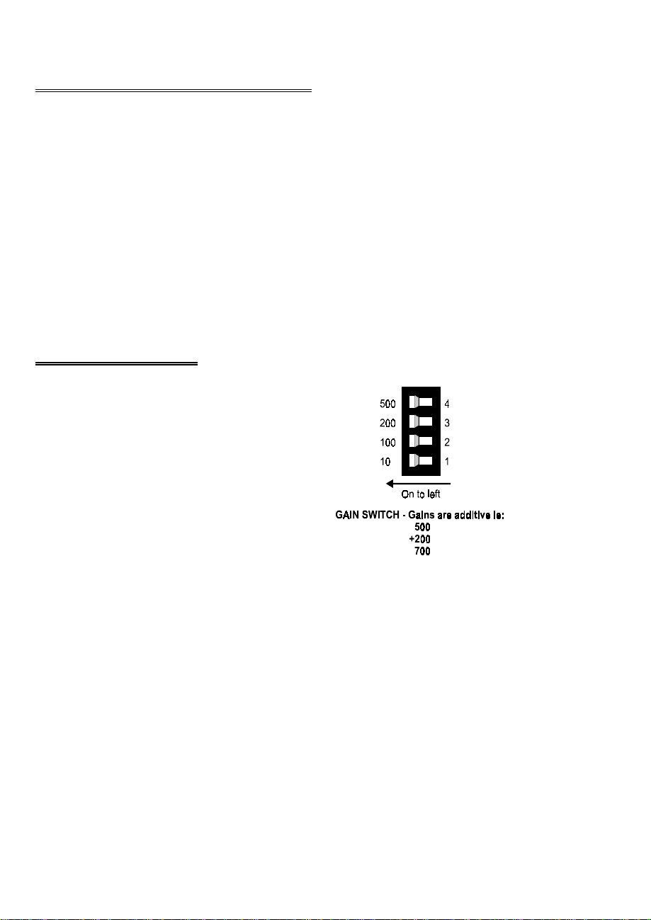
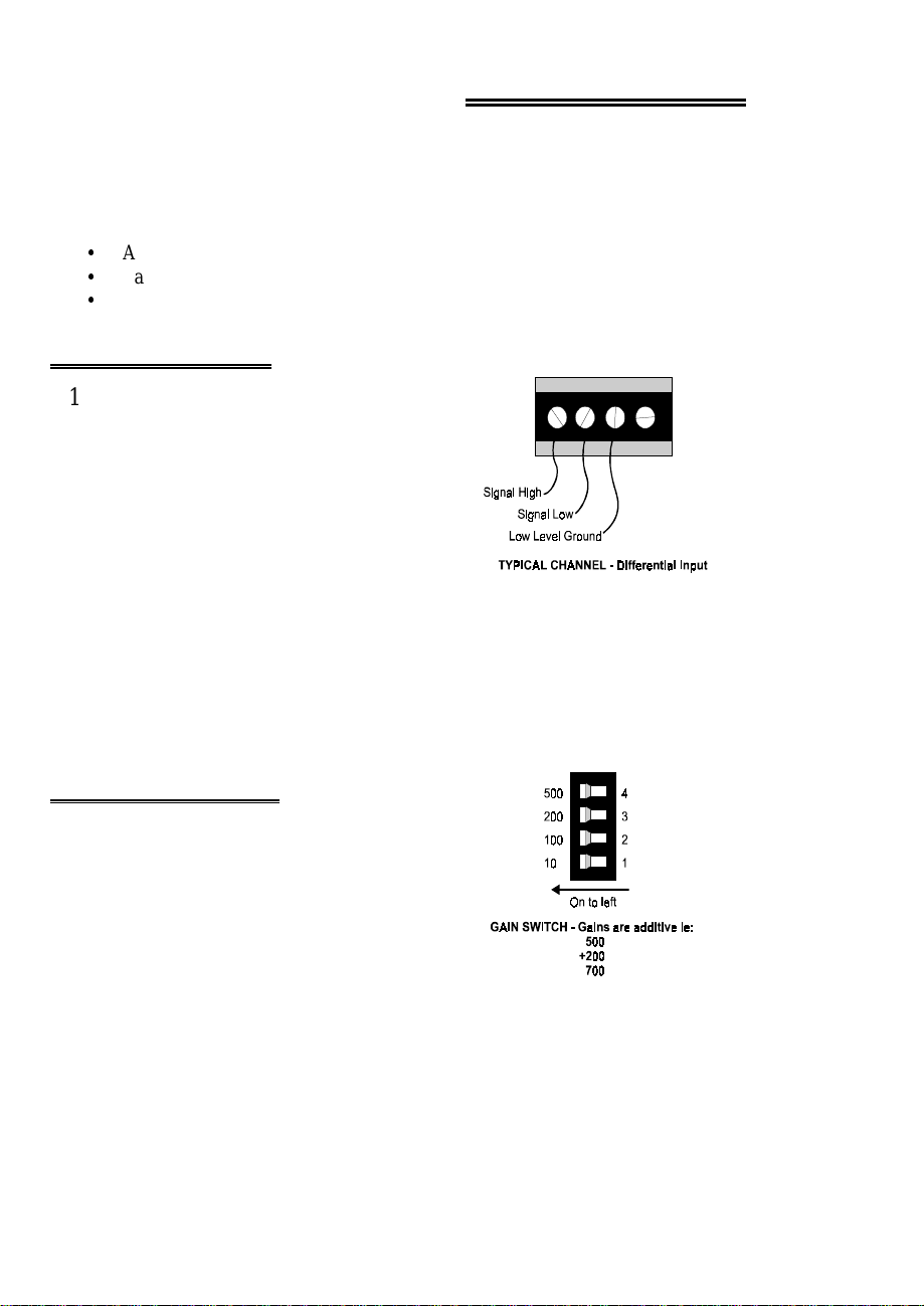
2.5 GAIN SWITCHES
Each amplifier has a quad DIP switch located
nearby. The four switches control the gain of one
amplifier. The gain settings are additive so a total
of 16 different gains (including 1) are possible.
The gain of a switch is added when the switch is to
the left and not added when the switch is to the
right.
Figure 1-5. Ganged Gain Switch
4
Page 9
3.0 SIGNAL CONNECTION
3.1 CONNECTOR DIAGRAM
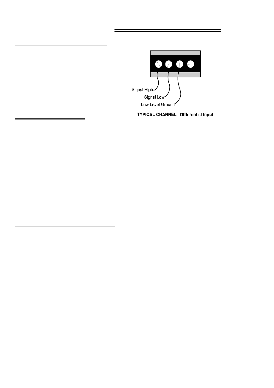
The CIO-SSH16 inputs are screw
terminals which will accept 12-22 AWG
wire.
Each channel has a screw terminal for
signal high, signal low and ground.
3.2 ANALOG INPUTS
Analog inputs to the CIO-SSH16 may be connected in two different configurations.
In order of complexity, these are Floating Differential and Differential.
WARNING - PLEASE READ
Measure the voltage between the grounds at the signal source and
the PC. Use a volt meter and place the red probe on the PC ground
and the black probe on the signal ground. If there is more than 10
volts, do not connect the CIO-SSH16 to this signal source because
you will not be able to make any reading. If the voltage is more
than 30 volts, DO NOT connect this signal to the CIO-SSH16
because it will damage the board and possibly the computer.
3.3 FLOATING DIFFERENTIAL
A floating differential input is two wires from the signal source and a ground reference
resistor (10 Kohms is a typical value) installed at the CIO-SSH16 input. The two
signals from the signal source are Signal High (CH# HI) and Signal Low (CH# LO).
The reference resistor is connected between the CIO-SSH16 CH# LO and LLGND
pins.
5
Page 10
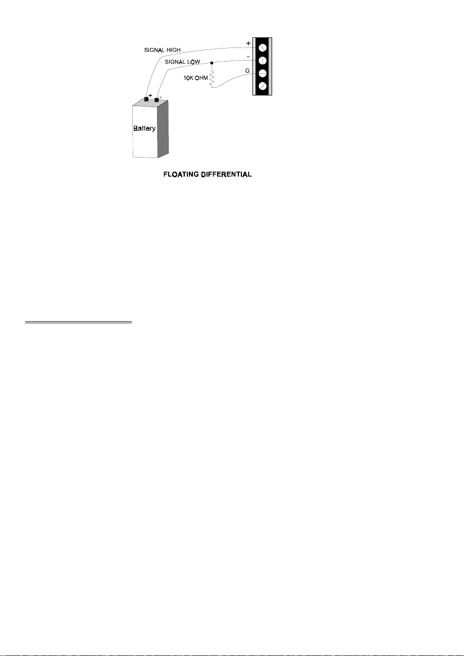
A floating differential hookup is handy when the signal source is floating with respect
to ground, such as a battery, 4-20 mA transmitter or thermocouple and the lead lengths
are long or subject to EMI interference.
The floating differential input will reject up to 10V of EMI energy on the signal wires.
WARNING!
Verify that the signal source is really floating. Check it with a
voltmeter before risking the CIO-SSH16 and PC!
3.4 DIFFERENTIAL
A differential signal is three wires from the signal source. The signals are Signal High
(CH# HI), Signal Low (CH# LO) and Signal Ground (LLGND).
A differential connection allows you to connect the CIO-SSH16 to a signal source
with a ground that different than the PC ground, but less than 10 V difference, and still
make a true measurement of the signal between CH# HI and CH# LO.
EXAMPLE:
6
Page 11
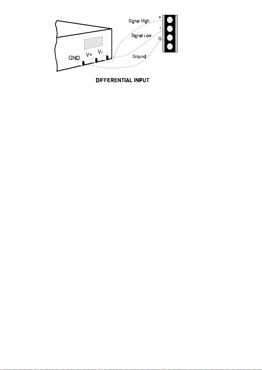
A laboratory instrument with its own wall plug. There are sometimes differences in
wall GND between outlets.
7
Page 12
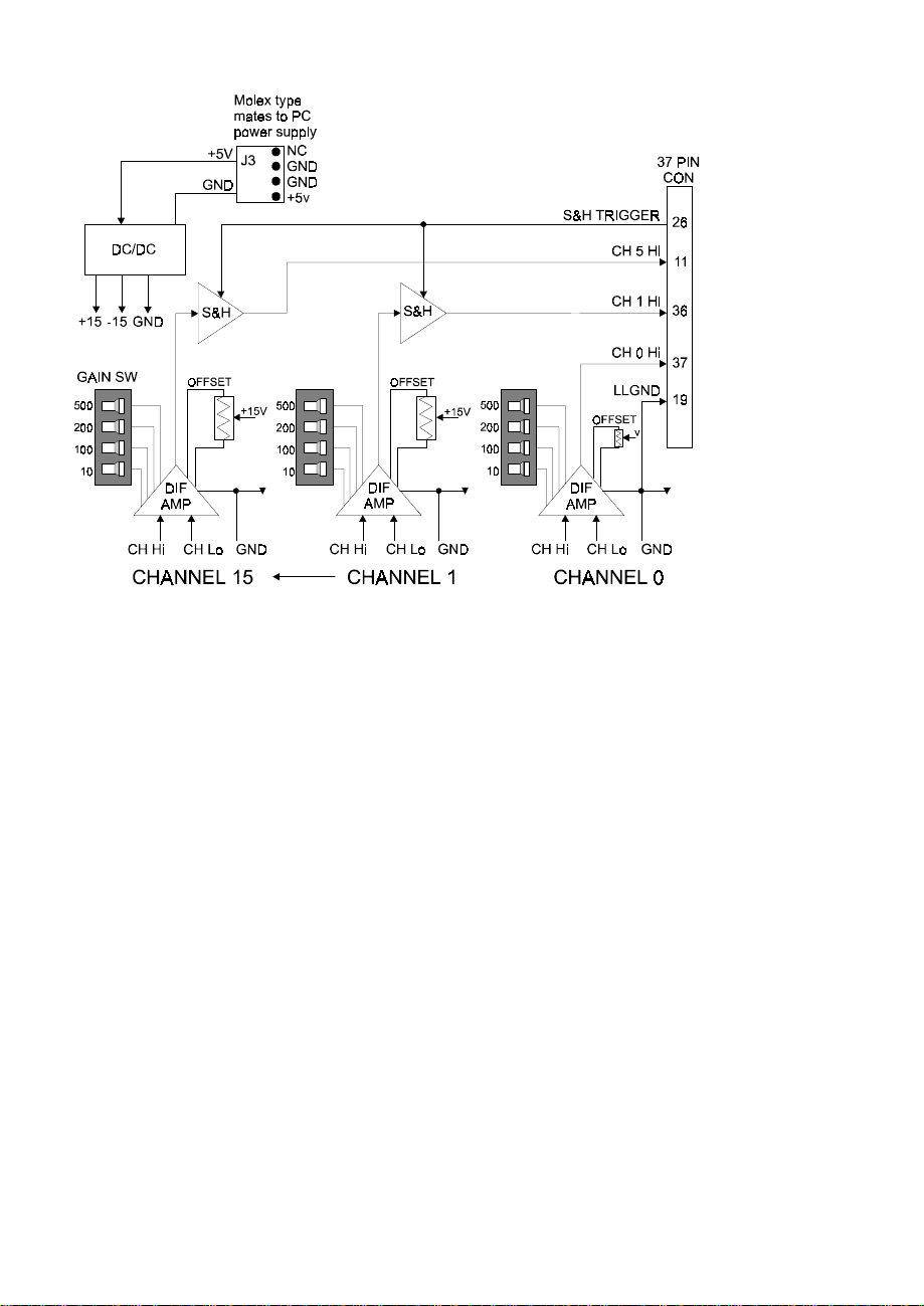
4.0 ARCHITECTURE
There are two types of functional elements on the CIO-SSH16; differential amplifiers
and a sample & hold chips (LF398). Together they provide differential input and
amplification for up to 16 channels of simultaneous sampling signal conditioning.
This section contains information on the following subjects:
y
Amplification. Gains & signal diagram.
y
Sample & Hold. Signal diagram, triggering, timing diagram.
y
4.1 ANALOG INPUT
Analog signal connections are made at screw
terminals located along the edge of the board.
These screw terminals will accept 12-22 AWG
wire and are of the high quality 'clamp' type
(Figure 4-3).
Each input channel has three terminals; signal
high, signal low and ground.
Figure 4-3. Analog Input Connection
The inputs are fully differential. There are two possible signal connections to a
differential input which are described in the section on analog electronics.
The screw terminal inputs feed directly into a differential amplifier, part no. IAN110.
There are no passive components on the trace between the screw terminal and the
IAN110.
4.2 AMPLIFICATION
Each channel is equipped with an INA110
differential amplifier, the gain of which is
controlled by a four position DIP switch (S1-S16
for channels 15 to 0; S1=ch15, etc.). The gain
settings are additive so a total of 16 different gains
(including 1) are possible..
Figure 4-4. Gain Switches
We suggest that the analog input board be configured for a range of +/-5V bipolar or 0
to 10V unipolar and that a CIO-SSH16 gain be chosen that amplifies your sensor
signal to that level. Fully amplifying the signal at the CIO-SSH16 provides a high
8
Page 13

level signal to the analog input boards single ended inputs, reducing the impact of
EMI or RFI along the signal cable between the CIO-SSH16 and the analog input
board.
4.3 CIO-SSH16 vs. PROGRAMMABLE GAIN A/D BOARDS
Having a dedicated differential amplifier for every channel produces flexible and
powerful data acquisition capability. Data throughput of independent amplifiers
exceeds that of A/D boards with single programmable gain amplifiers, even those
equipped with a channel/gain queue.
For example, a programmable gain amplifier is often desired so that signals with
different ranges can be measured using the A/D converter's full resolution.
There are two ways to implement programmable gain; the least expensive is to place a
programmable gain amplifier on the analog input and locate it's control register at one
of the A/D board's I/O addresses. The gain is changed by writing to the address. This
method works like switch-selectable gain except that the switch is in software. There
is one gain for all the analog inputs and changing it is done by writing to a register.
High speed acquisition using DMA rules out gain changes made during a sample run.
This scheme is inadequate if you want to change gains 'on the fly' and take samples at
high speed.
An on-board channel/gain queue is required to enable assigning a different gain to
each channel while data is being acquired at DMA speed. This adds considerable cost
and programming complexity to the A/D board.
Having independent gain amplifiers on each channel permits selecting optimum gain
without any degradation in speed.
Another useful application of programmable gain is to 'tune' the range of the A/D
board for the current value of a signal so that op timum resolution possible is o btained .
This is done by reading the signal, testing the level and adj usting the gain until A/D
board range and the optimum range is achieved.
An alternative and possibly better method of matching the A/D converter to the signal
is shown in Figure 4-5. Simply connect the signal to several of the CIO-SSH16 inputs.
Set each amplifier to a different gain. Data is collected at full speed!
9
Page 14
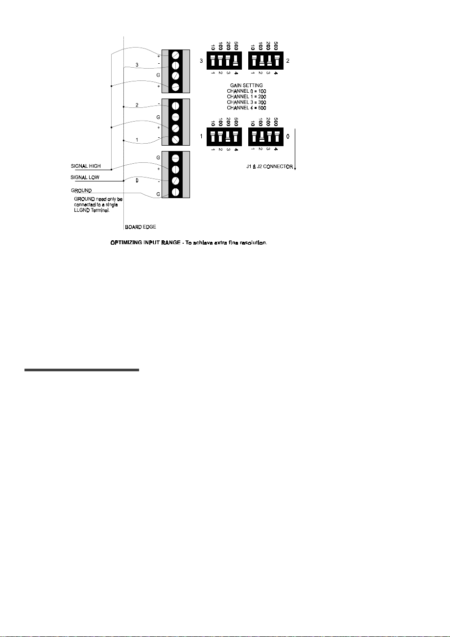
Figure 4-5. Input Range Optimization
During post-processing analysis, the range which provided the best resolution at any
point in time is instantly available.
The cost of a CIO-DAS16 and CIO-SSH16 is less than the cost of an A/D board with
a channel gain queue and far less than alternative simultaneous sample & hold
schemes. It certainly is more flexible.
4.4 SAMPLE & HOLD
You probably purchased the CIO-SSH16 for it's simultaneous sample & hold (S&H)
feature, and that was our primary design objective (Figure 4-6). The theory of
operation is simple. Sample & hold chips on each channel are synchronized to the
analog input boards sample & hold chip via pin 26 of the analog input board (SSH
OUT).
10
Page 15
S1
S15
S16
Figure 4-6. Input Amplifiers with Sample and Hold Chips
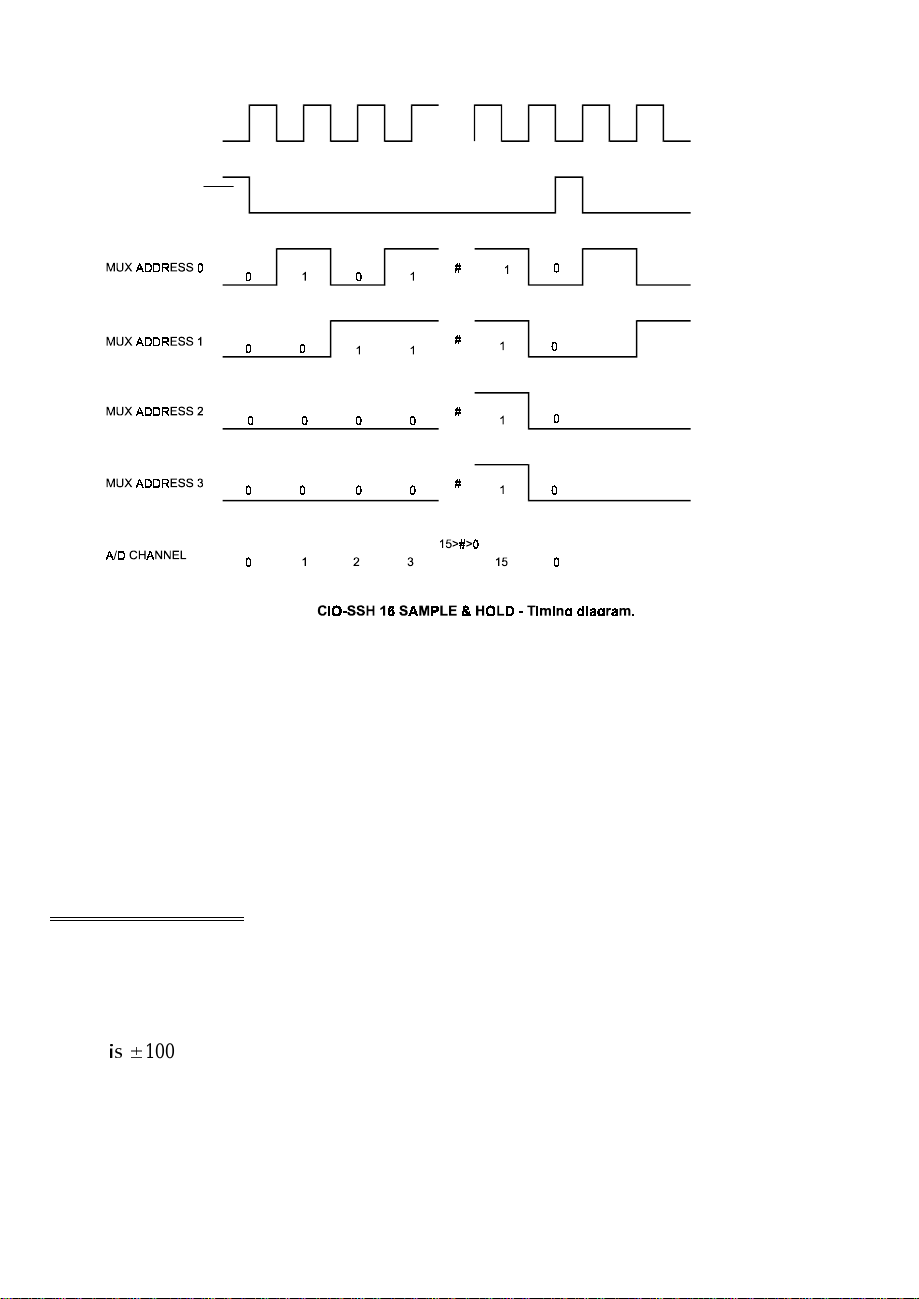
SSH OUT is synchronized to the analog input boards S&H chip and the channel select
MUX. When the analog input board samples channel 0, each of the LF398s on the
CIO-SSH16 also samples the signal on its input. Each of the LF398s then switches to
HOLD mode and the analog input board acquires this “held” signal from each
channel. The CIO-SSH16 remains in HOLD mode until the analog input board
samples channel 0 again.
11
Page 16
ANALOG INPUT BOARD’S
ON-BOARD SAMPLE-HOLD
CIO-SSH16 SAMPLE MODE CIO-SSH16 SAMPLE MODE
LF398 SAMPLE/HOLD
PIN 26
CIO-SSH16 HOLDS WHILE ANALOG IN BOARD
ACQUIRES DATA
Figure 4-7. Sample and Hold Timing Diagram
Note that Channel 0 of the CIO-SSH16 does not have an LF398 sample and hold chip.
That is because there is one sample and hold on the analog input board and it serves as
the S&H chip for CIO-SSH16’s channel 0. When the S&H on the A/D board is
sampling the signal on channel 0, the S&Hs on the CIO-SSH16 are sampling the
signals on channels 1 to n. When the S&H on the analog input board enters HOLD,
all the S&Hs on the CIO-SSH16 enter HOLD. The S&H chips on the CIO-SSH16
will remain in HOLD mode until the analog input board has acquired all of the
channels required and channel 0 is again sampled. In this way, signals for up to 16
channels are sampled simultaneously.
4.5 DROOP RATE
Droop rate is the rate at which the output of the sample and hold 'droops' from the
value it was in the instant the S&H entered HOLD mode. The specification on the
LF398
LV
100 uV/ms.
A droop implies that reading the output of the S&H as quickly as possible is desirable.
12
Page 17
To calculate the effect of the droop rate on the accuracy of your measurement, the
range of the signal, the resolution of the A/D converter and the time between HOLD
and A/D acquisition are needed. Here is an example.
RANGE CALCULATION
Signal Range ±50 millivolts
Gain 100
Amplifier Output ±5 Volts At full scale
RESOLUTION CALCULATION
A/D resolution 12 bits 1 part in 4096
Volts per bit 2.44 millivolts 10/4096
TIME TO SAMPLE CALCULATION
Number of channels 8
Sample Rate 4,000 samples/ sec.
Time between samples 250 microseconds 1/4000
Time from HOLD to CH8 2 milliseconds 0.000250 * 8
DROOP CALCULATION
Maximum droop to CH8 ±0.0001V * 2 = ±2 microvolts.
Less than 8% of the value of 1 bit.
It is clear from this calculation that droop rate is not a problem even at low sampling
rates. The sample rate would have to drop to less than 400 samples/ sec. over eight
channels before the droop was detectable by a 12 bit A/D converter.
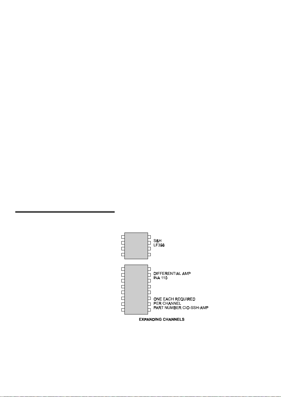
4.6 ADDING AMPLIFIERS &
SAMPLE / HOLD CHIPS
The CIO-SSH16 comes standard with
four amplifiers and three sample & hold
chips installed.
To add an additio nal channel, order the
two chip set, CIO-SSH-AMP shown
here. Twelve CIO-SSH-AMP chip sets
may be added for a total of 16 channels
(Figure 4-8). You can acquire LF398
S&H and INA110 amps on your own
and install them if you wish without
voiding your warranty.
Figure 4-8. CIO-SSH-AMP Chip Set
13
Page 18

5.0 SPECIFICATIONS
Typical for 25°C unless otherwise specified.
Power consumption
+5V 1.0A typical, 1.25A max
Analog input section
Input amplifier type INA110
Number of channels 16 differential
Input range ±10V
Gains X1, X10, X100, X110, X200, X210, X300, X310,
X500, X510, X600, X610, X700, X710, X800,
X810
Gain error
Gain = 1 0.02% max, 0.002% typical
Gain = 10 0.05% max, 0.005% typical
Gain = 100 0.1% max, 0.01% typical
Gain = 200 0.2% max, 0.02% typical
Gain = 500 0.5% max, 0.05% typical
Nonlinearity
Gain = 1 0.005% max, 0.0005% typical
Gain = 10 0.01% max, 0.001% typical
Gain = 100 0.01% max, 0.002% typical
Gain = 200 0.01% max, 0.003% typical
Gain = 500 0.02% max, 0.005% typical
Temperature coefficient
Gain = 1 ±20 ppm / Deg C
Gain = 10 ±20 ppm / Deg C
Gain = 100 ±40 ppm / Deg C
Gain = 200 ±60 ppm / Deg C
Gain = 500 ±100 ppm / Deg C
Offset ±15mV / Deg C
Calibration Offset manually adjustable to 0
Common Mode Range ±10V
CMRR @ 60Hz 90 dB
Input leakage current 200 pA
Absolute maximum input voltage ±35V
14
Page 19

Sample / hold section
Sample / hold type LF398
Aperture time 250 ns max, 150 ns typical
Aperture uncertainty 50 ns typical
Acquisition time 10 µs max
Temperature coefficient 4 ppm/°C
Droop rate ±100µV/ms
RMS Noise (10 kHz to 100 kHz) 10µV
Current Drive ±5 mA
Output coupling DC
Output impedance 0.1 Ohms max
Miscellaneous TTL high level for sample mode,
TTL low level for hold mode
Environmental
Operating temperature range 0 to 60°C
Storage temperature range −40 to 80°C
Humidity 0 to 90% non-condensing
15
Page 20
6.0 ANALOG ELECTRONICS
This short introduction to the analog electronics most often needed by data acquisition
board users describes the following:
y
Voltage dividers.
y
Differential vs. Single Ended Inputs.
y
Isolation vs. Common Mode Range
y
Low pass filters for analog and digital inputs.
y
A/D Resolution
y
Conversion to Engineering units.
y
4-20 mA inputs
y
Noise; sources and solutions.
y
Digital interfacing.
Each deals with the impact on measurements made with data acquisition boards. For
additional information on the subject of data converters and analog electronics, Radio
Shack has written an excellent Op Amp handbook and has an Op Amp experimenters
kit.
A more advanced treatment is in the Analog-Digital Conversion Handbook (32.95)
and the Transducer Interfacing Handbook ($14.50) published by Prentice-Hall.
6.1 VOLTAGE DIVIDERS
If you wish to measure a signal which varies over a range greater than the input range
of an analog or digital input, a voltage d ivider will drop the vo ltage of the input signal
to the safe level the analog or digital input can measure.
A voltage divider takes advantage of Ohm's law, which states,
Voltage = Current * Resistance
and Kirkoff's voltage law which states,
The sum of the voltage drops around a circuit will be equal to the voltage
drop for the entire circuit.
Thus, any variation in the voltage drop for the circuit as a whole will have a
proportional variation in all the voltage drops in the circuit (Figure 6-1).
16
Page 21
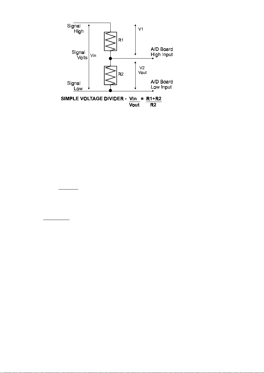
Figure 6-1. Voltage Divider
The object in using a voltage divider is to choose two resistors with the proper
proportions relative to the full scale of the analog or digital input and the maximum
signal voltage.
Dropping the voltage proportionally is often called attenuation. The formula for
attenuation is:
The variable Attenuation is the proportional
Attenuation = R1 + R2
R2
2 = 10K + 10K
10K
difference between the signal voltage max and the
full scale of the analog input.
For example, if the signal varies between 0 and 20
volts and you wish to measure that with an analog
input with a full scale range of 0 to 10 volts, the
Attenuation is 2:1 or just 2.
R1 = (A-1) * R2
Digital inputs also make use of voltage dividers, for example, if you wish to measure a
digital signal that is at 0 volts when off and 24 volts when on, you cannot connect that
directly to the CIO-DAS16 digital inputs. The voltage must be dropped to 5 volts
max when on. The Attenuation is 24:5 or 4.8. Use the equation above to find an
appropriate R1 if R2 is 1K. Remember that a TTL input is 'on' when the input voltage
is greater than 2.5 volts.
For a given attenuation, p ick a handy resistor and
call it R2, the use this formula to calculate R1.
17
Page 22
IMPORTANT NOTE: The resistors, R1 and R2, are going to dissipate all the power
in the divider circuit according to the equation Current = Voltage / Resistance. The
higher the value of the resistance (R1 + R2) the less power dissipated by the divider
circuit. Here is a simple rule:
For Attenuation of 5:1 or less, no resistor should be less than 10K.
For Attenuation of greater than 5:1, no resistor should be less than 1K.
The CIO-TERMINAL has the circuitry on board to create custom voltage dividers.
The CIO-TERMINAL is a 16" by 4" screw terminal board with two 37 pin D type
connectors and 56 screw terminals (12 - 22 AWG). Designed for table top, wall or
rack mounting, the board provides prototype, divider circuit, filter circuit and pull-up
resistor positions which you may complete with the proper value components for your
application.
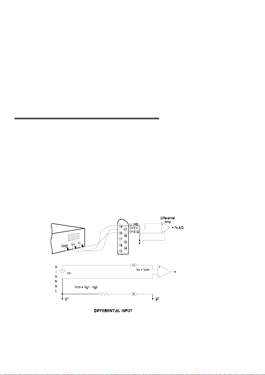
6.2 DIFFERENTIAL & SINGLE ENDED INPUTS
Two type of analog inputs are commonly found on A/D boards, they are differential
and single ended. Single ended is the less expensive of the two.
COMMON MODE RANGE
Differential inputs have a common mode range (CMR) (Vcm). Single ended inputs
have no CMR. Co mmon mode range is the voltage r ange over which differ ences in
the low side of the signal and A/D input ground have no impact on the A/D's
measurement of the signal voltage. A differential input can reject differences between
signal ground and PC ground.
Figure 6-2 shows a differential mode input.
Figure 6-2. Differential Input
18
Page 23
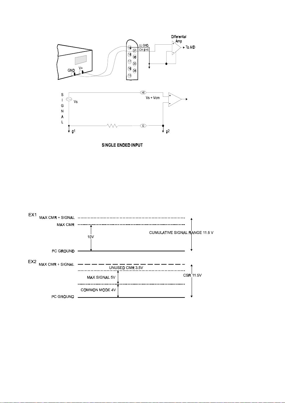
A single ended input has no common mode range because there is only one LOW
wire, which is assumed to be at the same level at the signal and at the A/D board.
Figure 6-3. Single-Ended Input
The maximum difference which may be rejected is the CMR.
For example, the CIO-SSH16 has a common mode plus signal range of 11.5 volts,
common mode not to exceed 10 volts.
This specification is illustrated graphically here and will be referred to as Cumulative
Signal Range (CSR).
Figure 6-4. CSR
Most manufactures of A/D boards specify the CMR directly from the component data
sheet, ignoring the effect of the board level system on that specification. A data sheet
of that type might claim 10 volts of CMR. Although this is a factual specification and
19
Page 24

the designer of the board (or other EE) would be able to translate that into a systems
specification, most A/D board owners are confused or mislead by such specs.
6.3 COMMON MISUNDERSTANDINGS
The CMR specification of a differential input is often confused with an isolation
specification, which it is not. CMR of 10 volts is not the same as 10 volts of isolation.
The graph above shows why.
Also, failure to specify the common mode plus signal system specification leads
people to believe that a DC offset equal to the component CMR can be rejected
regardless of the input signal voltage. It cannot as the graph above illustrates.
When is a differential input useful? The answer is whenever electromagnetic
interference (EMI) or radio frequency interference (RFI) may be present in the path of
the signal wires. EMI and RFI can induce voltages on both signal wires and the effect
on single ended inputs is generally a voltage fluctuation between signal high and
signal ground.
A differential input is not affected in that way. When the signal high and signal low of
a differential input have EMI or RFI voltage induced on them, that common mode
voltage is rejected, subject to the system constraint that common mode plus signal not
exceed the A/D board's CSR specification.
6.4 GROUND LOOPS
Ground loops are circuits (E=I*R) created when the signal ground and the PC ground
are not the same. Ground loop inducing voltage differential may be a few volts of
hundreds of volts. They may be constant or transient (spike s). A differential input
will prevent a ground loop as long as the CSR specifications is not exceeded.
If ground differences greater than the CMR are encountered, isolation is required.
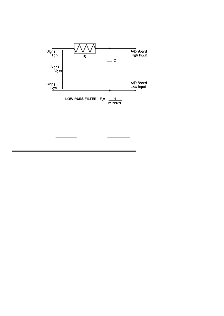
6.5 LOW PASS FILTERS
A low pass filter is placed on the signal wires between a signal and an A/D board. It
stops frequencies greater than the cut off frequency from entering the A/D board's
analog or digital inputs.
The key term in a low pass filter circuit is cut-off frequency. The cut-off frequency is
that frequency above which no variation of voltage can enter the circuit. For example,
if a low pass filter had a cut-off frequency of 30 Hz, the kind of interference
20
Page 25
associated with line voltage (60 Hz) would be filtered out but a signal of 25 Hz would
be allowed to pass.
Also, in a digital circuit, a low pass filter is often used to filter an input from a switch.
Figure 6-5. Low pass Filter
A low pass filter may be constructed from one resistor (R) and one capacitor (C). The
cut off frequency is determined according to the formula:
Fc = 1
2*Pi*R*C
R = 1
2*Pi*C*F
c
6.6 A/D RESOLUTION & ENGINEERING UNITS
Resolution is specified in bits, such as 8, 10 or 12 bits. The 12 bits are really a power
of 2 indicating the number of divisions of full scale the converter can resolve. For
example, a 12 bit converter can resolve (2
input of the board were +/- 5 volts full scale, each of the 4095 steps would be equal to
0.00244 volts.
Reading from the A/D converter would be thus:
Converter # Volts
4095 4.9976
4094 4.9951
4093 4.9927
2048 0.0
1 − 4.9976
0 − 5.0
12
) = 4096 divisions of full scale. If the
21
Page 26

Resolution is a measure of the ability to differentiate between one voltage and another.
Obviously, the more bits of resolution (13 bits = 8192 counts) the more divisions of
full scale. The more divisions of full scale, the higher the resolution of the
measurement.
6.7 ENGINEERING UNITS
When a program uses an A/D board to acquire data, the data file is filled with
numbers like those above.
To translate the A/D numbers back into the engineering units of the original
measurement, we need to know:
The sensor's voltage output per engineering unit.
The full scale range of the board at the time the measurement was made.
The resolution of the converter.
Here is an example from the application note on interfacing a Voland TA to a PC
found elsewhere in this manual.
The TA measures resistance in grams between +500 and −500 grams.
The voltage output of the instruments is +2.5 volts to −2.5 volts.
The voltage output corresponds to the grams of pressure exactly, so:
+/- 500 grams = 1000 grams.
+/- 2.5 volts = 5 volts.
5 volts / 1000 grams = 0.005 volts per gram.
The A/D was set for +/- 2.5 volts = 5 volts full scale.
5 volts / 4096 counts = 0.00122 volts per bit.
If the number in the file for one reading was 3061, then
3061 * 0.00122 = 3.7366 volts.
3.7366 volts / 0.005 volts per gram = 747 grams.
Now shift from full scale to +/- scale.
747 grams full scale − 500 = 247 grams of positive pressure.
It may look like a lot of steps because it is presented that way here for clarity only. It
could be expressed as a single equation in a spreadsheet.
6.8 CURRENT LOOP (4-20 mA)
Although the inputs of a CIO-DAS16 board are voltage inputs, it is easy to convert a
current to a proportional voltage which may be measured by the CIO-DAS16 board.
The current is converted to a proportional voltage by the formula V=I*R (Ohm’s law).
22
Page 27
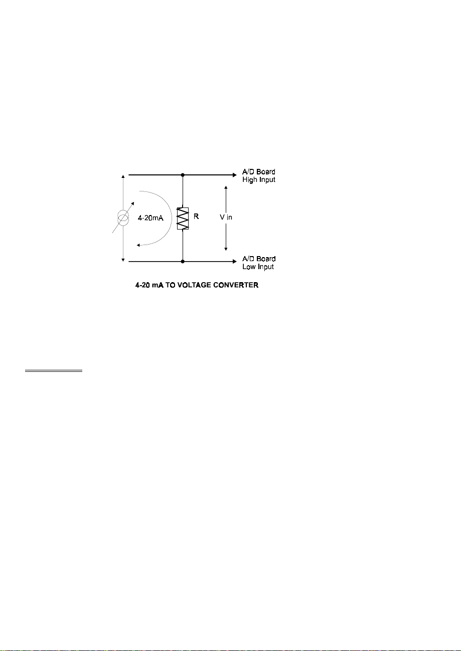
For example, if the CIO-DAS16 board is set up to read 0 to 5 volts, then:
5 volts / 0.02 Amps = 250 Ohm shunt resistor.
So a full 20 mA will register 5 volts and 4 mA will register 1 volt.
To hook up the CIO-DAS16 analog inputs to a 4-20 mA transducer or signal source,
place the shunt resistor across the plus and minus terminals or signal wires of the 4-20
mA. Once the resistor is in place, connect the analog input CH# Hi to the plus
terminal and the analog input CH# Lo to the minus input.
Figure 6-6. Current-to-Voltage Resistor
If they are backward, the A/D reading will be 0 or minus volts. Just reverse the
connection.
6.9 NOISE
Noise is unavoidable in PC based data acquisition systems. There is board-induced
noise which can be measured by shorting an analog input to ground and taking a series
of readings and plotting them in a histogram. There is EMI and RFI-induced noise
along the path of the signal wires. There is also noise at the signal source itself. All
these sources of noise combine to create a region of uncertainty around the signal
value.
Our objective here is to list the sources of noise and give some means to reduce it.
6.9.1 SOURCES OF NOISE
The first source of noise is the board itself. Manufacturers of A/D boards quote
component specifications in their data sheets but rarely quote a system specification
for general accuracy and noise. The reasons being that the system specification would
be less accurate than component specification and that system specifications must also
23
Page 28

specify the conditions under which the specification was made. That means the PC,
the PC's power supply and the connection to the front end.
Put some very good components on a circuit board and place that board in a PC and
the system will be less accurate than the individual components. Some 12-bit A/D
boards with the same components as a CIO-DAS16 have as little as nine bits of
accuracy, due to board noise.
The system specification for the CIO-SSH16 and CIO-DAS16 is +/- 1 LSB. That
means that if an analog input is tied to ground and the CIO-SSH16 is on a bipolar
scale, the reading will be 2048 90% of the time. The other 10% of the readings will
be 2047 and 2049, which is +/- one count (LSB). This is actually not very different
from the component specifications.
You can verify this by grounding an analog input channel to LLGND, taking 1000
readings, then plotting a histo gram of those readings. (If your histogram is not +/- 1
LSB, check the +/- 12V PC power supply voltages.)
6.9.2 SIGNAL WIRE NOISE
Signal wires, especially single-ended inputs, are subject to EMI and RFI, both of
which can induce noise on the wires carrying the transducer signal to the CIO-DAS16
board. Fortunately, signal wire noise is often localized and can be reduced by
repositioning the signal wire run and/or shielding.
To check for signal wire noise, first, short analog channel 0 to low level ground* at
the connector and take 10,000 samples and plot the histogram. This is the best the
signal can be and is what you will try to achieve with the signal wires in place.
After you have an ideal case histogram, remove the short between analog input 0 and
low level ground. Attach the signal wires to the CIO-DAS16 board inputs and run
them to the sensor. Do not connect the sensor yet, just short the analog input(s) to
LLGND.
Take data for the histogram and compare it to the best case data taken previously. If it
shows noise, you can try to eliminate the noise by doing the following:
y
Move the signal wires, trying to locate a 'quiet' run.
y
Use a shielded twisted pair as the signal wire. Attach the shield at the PC
end only. If the shield is attached at both the PC and the sensor it may create
a ground loop and add to signal interference.
6.9.3 SENSOR NOISE
When the signal wires have been tested and characterized for signal quality, connect
the sensor and provide a known level to the sensor (ice bath for temp., etc.) then take
data for the histogram plot. If additional noise has been introduced by the sensor
which exceeds the sensor specifications, you can try moving the sensor or electrically
isolating it from the device it is measuring.
24
Page 29

6.9.4 SMOOTHING DATA
It is not always possible to eliminate all noise, especially with very low level sensors,
but noise looks terrible when plotted and can raise doubts about otherwise excellent
data. There are two simple ways to eliminate noise from the data:
1. Apply a moving average to the data if you want to retain the same apparent
accuracy.
2. Remove the information from the noisy range. For example, if a 12 bit A/D
converter is at +/- 5 volts (10 volts full scale) then one LSB = 10 / 4096 =
0.00244mV. If your system is inducing +/- 0.007mV of noise (+/- 3 counts),
round all the readings by +/- 3 counts. In this way the reading's value reflects
the true accuracy of the system.
25
Page 30

For your notes.
26
Page 31

EC Declaration of Conformity
Measurement Computing Corp.
We,
, declare under sole responsibility that the product:
CIO-SSH16
DescriptionPart Number
to which this declaration relates, meets the essential requirements, is in conformity
with, and CE marking has been applied according to the relevant EC Directives listed
below using the relevant section o f the following EC standards and other no rmative
documents:
EU EMC Directive 89/336/EEC: Essential requirements relating to electromagnetic
compatibility.
EU 55022 Class B: Limits and methods of measurements of radio interference
characteristics of information technology equipment.
EN 50082-1: EC generic immunity requirements.
IEC 801-2: Electrostatic discharge requirements for industrial process measurement
and control equipment.
IEC 801-3: Radiated electromagnetic field requirements for industrial process
measurements and control equipment.
IEC 801-4: Electrically fast transients for industrial process measurement and control
equipment.
Carl Haapaoja, Director of Quality Assurance
Page 32

Measurement Computing Corporation
16 Commerce Boulevard,
Middleboro, Massachusetts 02346
(508) 946-5100
Fax: (508) 946-9500
E-mail: info@measurementcomputing.com
www. measurementcomputing.com
 Loading...