

Page 1

CIO-LAB8-TERM ™
Educational Board
User’s Manual
Revision 2
October, 2001
Copyright 2001, MEASUREMENT COMPUTING CORPORATION
©
Page 2

LIFETIME WARRANTY
Every hardware product manufactured by Measurement Computing Corp. is warranted against defects in materials or
workmanship for the life of the product, to the original purchaser. Any products found to be defective will be
repaired or replaced promptly.
LIFETIME HARSH ENVIRONMENT WARRANTY
TM
Any Measurement Computing Corp. product which is damaged due to misuse may be replaced for only 50% of the
current price. I/O boards face some harsh environments, some harsher than the boards are designed to withstand.
When that happens, just return the board with an order for its replacement at only 50% of the list price. Measurement
Computing Corp. does not need to pro fit from your misfortune. By the way, we will honor this warranty for any other
manufacture’s board that we have a replacement for!
30 DAY MONEY-BACK GUARANTEE
Any Measurement Computing Corp. product may be returned within 30 days of purchase for a full refund of the
price paid for the product being returned. If you are not satisfied, or chose the wrong product by mistake, you do not
have to keep it. Please call for a RMA number first. No credits or returns accepted without a copy of the original
invoice. Some software products are subject to a repackaging fee.
These warranties are in lieu of all other warranties, expressed or implied, including any implied warranty of
merchantability or fitness for a particular application. The remedies provided herein are the buyer’s sole and exclusive remedies. Neither Measurement Computing Corp., nor its employees shall be liable for any direct or indirect,
special, incidental or consequential damage arising from the use of its products, even if Measurement Computing
Corp. has been notified in advance of the possibility of such damages.
MEGA-FIFO, the CIO prefix to data acquisition board model numbers, the PCM prefix to data acquisition bo ard
model numbers, PCM-DAS08, PCM-D24C3, PCM-DAC02, PCM-COM422, PCM-COM485, PCM-DMM,
PCM-DAS16D/12, PCM-DAS16S/12, PCM-DAS16D/16, PCM-DAS16S/16, PCI-DAS6402/16, Universal Library,
InstaCal, Harsh Environment Warranty and Measurement Computing Corp. are registered trademarks of Measurement Computing Corp.
IBM, PC, and PC/AT are trademarks of International Business Machines Corp. Windows is a trademark of Microsoft Corp. All other trademarks are the property of their respective owners.
Information furnished by Measurement Computing Corp. is believed to be accurate and reliable. However, no
responsibility is assumed by Measurement Computing Corp. neither for its use; nor for any infringements of patents
or other rights of third parties, which may result from its use. No license is granted by implication or otherwise under
any patent or copyrights of Measurement Computing Corp.
All rights reserved. No part of this publication may be reproduced, stored in a retrieval system, or transmitted, in any
form by any means, electronic, mechanical, by photocopying, recording or otherwise without the prior written
permission of Measurement Computing Corp.
Notice
Measurement Computing Corp. does not authorize any Measurement Computing Corp. product for
use in life support systems and/or devices without the written approval of the President of
Measurement Computing Corp. Life support devices/systems are devices or systems which, a) are
intended for surgical implantation into the body, or b) support or sustain life and whose failure to
perform can be reasonably expected to result in injury. Measurement Computing Corp. products
are not designed with the components required, and are not subject to the testing required to
ensure a level of reliability suitable for the treatment and diagnosis of people.
HM CIO-LAB8-TERM.lwp
Page 3

Table of Contents
1 Introduction .............................................................
2 Supporting Texts .........................................................
3 Installation of the CIO-LAB8-TERM ........................................
4 Component Installation ....................................................
1
1
2
2
2 4.1 Circuit Interconnection ..................................................
3 4.2 Component Placement ..................................................
3 4.3 Matching the schematic to the board. .......................................
45 Force Imaging Technology Pressure Transducer ...............................
Page 4

This page is blank.
Page 5

1 Introduction
Measurement Computing’s CIO-LAB8-TERM is an educational circuit experimentation board
designed to interface to the CIO-DAS08 AND CIO-DAS08/Jr. Included on the board are circuits
for:
Momentary contact switches (4)
Pull-up resistors (8)
Pull-down resistors (8)
SPST switch (8)
DPST relays (2)
LED bar display (8 LEDs)
Operational amplifier (2)
RC filters (2)
Resistor divider voltage dividers (2)
Resistive shunts (3)
Potentiometers (2)
Semiconductor temperature sensors (2)
Prototype area of 96 sockets. Room for four, 8-pin chips plus discreet components.
Pressure transducer kit location from Force Imaging Technology (kit is not included)
CIO-DAS08, DAS08-PGH, DAS08-AO connector
CIO-DAS08/Jr, DAS08/Jr-AO connector
Power, Ground, ±12V when available from DAS board connector
Sockets for access to all DAS board signals
2 Supporting Texts
There are two supporting texts available to guide your experiments and lab work with the
CIO-LAB8-TERM. These are:
Computer Interfacing: A Practical Guide to Data Acquisition and Control by Dr. William Rigby
and Terry L. Dalton of the University of Michigan, and
Computer Interfacing Laboratory Manual, also by Rigby and Dalton.
Both are published by Prentice Hall and can be purchased from Measurement Computing Corp.
Computer Interfacing Laboratory Manual was written specifically for use with the
CIO-LAB8-TERM. It contains a full semester's experiments employing the circuits on the board.
1
Page 6

3 Installation of the CIO-LAB8-TERM
There is really nothing to install. Simply connect the CIO-LAB8-TERM to a compatible data
acquisition board through the 37-pin connector and run the software you intend to use with the
data acquisition board.
CIO-LAB8-TERM is a front-end circuit experimentation board. The effect it has on your
measurements and the way the circuits interact with the software is entirely dependent on the
components you populate the circuits with.
You must understand the principles of electronics and the relationship of the circuits to the
data acquisition board and software, and use to properly apply the circuits.
The circuits on the CIO-LAB8-TERM are not populated. It is up to you to choose the
components to complete the circuits. These choices are not difficult to make, but do require you
to apply the rules of sound electrical engineering practices to choose the components that will
have the desired effect in the circuit.
In general, we cannot choose components for you and do not provide advice of that type over the
phone.
Components such as resistors and capacitors are not available from Measurement Computing. A
good local source of supply may be found at a Radio Shack store or check the yellow pages for
Electronic Components. Another excellent source is DigiKey, an mail order supplier of every
component imaginable. They may be reached at 1-800 DIGIKEY (800-344-4539) and will be
happy to send you a catalog.
4 Component Installation
This section of the manual will help you use the sockets installed on the board to install
components and connect the circuits to the data acquisition board connector (Figure 4-1).
4.1 Circuit Interconnection
Each circuit has sockets for components and for the circuit inputs and outputs. Connection to the
board’s 37-pin connector and to other circuits are made by wires inserted into the sockets. These
jumper wires can be made by stripping 1/4-inch off each end of a 22 or 24AWG sol id wire with
plastic insulation. Use different colors of wire to keep signals separate, such as red for power,
black for ground and green, blue, yellow or orange for analog and digital control signals.
NOTICE: Use only the approved wire gauge in the sockets. Wire larger than 22AWG may
damage sockets necessitating replacement of the socket.
2
Page 7
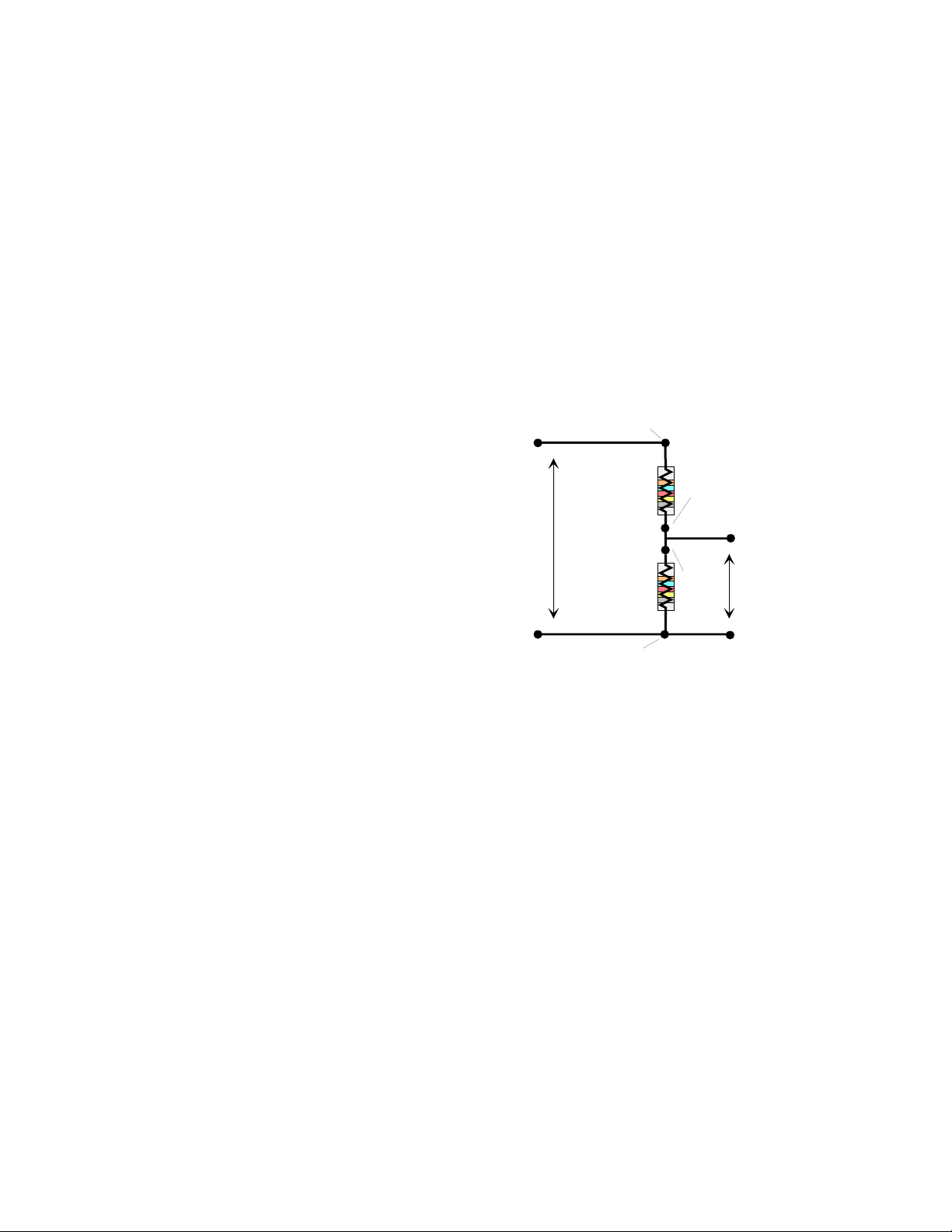
4.2 Component Placement
D
Place components for each circuit, such as the resistors needed to complete the resistor voltage
divider circuit shown below, in the labeled socket. The leads of a standard 1/4 watt resistor are
24AWG and are OK to insert into the sockets. If the component has over- or undersized leads,
solder on some waste clippings from 1/4-watt resistors, or use 24AWG wire.
NOTE: Although there holes in the board for every component, we recommend that they not be
used unless some permanent component is decided upon, such as the known value in a college
lab circuit.
CAUTION:
will most surely pull off the solder pad on the component side of the board and damage the
circuit.
Never attempt to remove a soldered-in component by heating and pulling it, you
Please use the sockets only
.
R11
RES IN
RES
IN
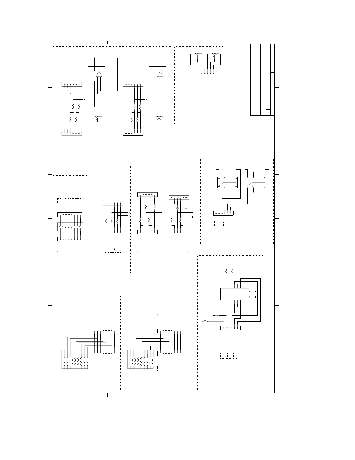
4.3 Matching the schematic to
the board.
Figure 4-1 shows a voltage divider circuit
as it appears on the board. Refer to this
INPUT
diagram, the board layout on Figure 4-2,
and sheet 1 of following schematics.
In the block labeled RESISTIVE
Volts In
R12
RES
OUT
OUT
Volts Divided
DIVIDERS, there are 2 circuits, A and B.
Circuit A is composed of resistors R11
and R12.
PC GROUND
RES OUT
PC GROUN
Figure 4-1. Voltage Divider Circuit
The two parallel rows of sockets appear on the schematic exactly as they are on the board. The
names of the signals are also exactly as they are written on the board. The pin labeled INPUT is
the high side (+) of the voltage to be divided. The pin labeled OUT is the high side of the
divided signal. Connect it to the A/D input.
The low sides of the voltage-in and voltage-out are connected to PC bus-ground on the board
and require no further connection.
Insert the divider resistors for input voltage in the sockets labeled RES IN for R11 and RES OUT
for R12.
The remainder of the circuitry is self-explanatory. For more information on resistor voltage
dividers please refer to any introductory electronics text.
The other circuits on the board are similarly shown on the schematic, and labeled on the board.
In all cases, where a circuit is shown connected to ground, the ground is PC chassis ground.
3
Page 8

Figure 4-1. Board Layout
5 Force Imaging Technology Pressure Transducer
There is a circuit and a connector on the CIO-LAB8-TERM exclusively for use with a FIT
pressure transducer. FIT sells a kit which contains a pressure transducer, cable and software.
Please contact FIT to learn more about the kit. Call (708) 674-7665 or fax (708) 674-6355.
4
Page 9
NC
AMP1 OUT
16J2
R1R2R3
12345
16J1
IN(-)
IN(+)
R(+)/GND
RIN(+)
R4
RIN(+)
R(+)/GND
R(-)FB
RIN(-)
6
RIN(-)
R(-)FB
20K
20K
R52
R53
6
+
-
ON
ON
OP07
U1
2
813
NC
AMP2 OUT
16J4
RIN(+)
R(+)/GND
RIN(-)
R(-)FB
6
12345
+
-
ON
ON
OP07
U2
2
813
6
16J11
TOP
TOP
WIPER
WIPER
BOTTOM
BOTTOM
COMPUTER BOARDS
20K
R50
VCC
R8
R5R6R7
12345
16J3
IN(-)
IN(+)
RIN(+)
R(+)/GND
AMPLIFIER #1 CIRCUIT
6
RIN(-)
R(-)FB
20K
R51
VCC
INDEPENDANT 20 KOHM POTENTIOMETERS
AMPLIFIER #2 CIRCUIT
POTENTIOMETER A
POTENTIOMETER B
2
2
REV
02/24/95
CIO-LAB8-TERM
COMPATIBLE I/O SERIES
COPYRIGHT 1995 COMPUTER BOARDS, INC.
EGE
DATE: SHEET 1 OF
D
SWITCH
OUTPUTS
OUT A
OUT B
OUT C
OUT D
OUT E
OUT G
OUT H
OUT I
7
15
IN B
13
14
IN C
IN D
SWITCH
INPUTS
4
12
IN E
5
6
11
6
IN F
678
10
7
IN G
8
9
8
8
IN H
S5
RESISTIVE SHUNTS TO GROUND
8 POSITION DIP SWITCH
PULL DOWN
OUT A
OUT B
OUT C
12345
1
J16
9
1234567
10
1
J15
IN A
IN B
IN C
PULL DOWN
12345
1
J18
16
12345
1234567
1
J17
IN A
PULL DOWN BLOCK
TO GROUND THROUGH 2.2KOHM
123
2.2K Ohm
000000
RN2
10K OHM
xxxxxxxx
xxxxxxx
0000000
8765 43 21
RESISTOR
16J10
R15
R16
12345
16J9
RESISTOR
SHUNT A
OUTPUTS
OUT D
OUT E
6
IN D
IN E
INPUTS
RESISTOR
SHUNT A OUT
SHUNT B OUT
RESISTOR
R17
6
INPUT
INPUT
INPUT
RESISTOR
RESISTOR
SHUNT B
SHUNT C
OUT G
OUT H
OUT I
7
8
8
IN F
IN G
IN H
RES (IN)
DIVIDER A(OUT)
SHUNT C OUT
16J8
R12
R11
12345
16J7
INPUT
RES (IN)
DIVIDER A
RESISTIVE DIVIDERS
PULL UP BLOCK
TO +5 THROUGH 2.2KOHM
+5
123
678
4
5
2.2K Ohm
000000
RN1
10K OHM
xxxxxxxx
xxxxxxx
0000000
RES (OUT)
RES (IN)
DIVIDER B(OUT)
RES (OUT)
R14
R13
6
INPUT
RES (IN)
RES (OUT)
RES 9OUT)
DIVIDER B
J14
9
10
J13
RESISTOR
FILTER A(OUT)
16J6
R9C1R10
12345
16J5
INPUT
RESISTOR
FILTER A
RC FILTER CIRCUITS
PULL UP
OUTPUTS
OUT A
OUT B
OUT C
OUT D
OUT E
OUT G
12345
6
1
1234567
1
IN A
IN B
IN C
IN D
IN E
IN F
PULL UP
INPUTS
RESISTOR
FILTER B(OUT)
CAPACITOR
C2
6
INPUT
RESISTOR
CAPACITOR
CAPACITOR
FILTER B
OUT H
OUT I
7
8
8
IN G
IN H
CAPACITOR
RLY01+5
14
9
16
TOP VIEW
8
3
1
12345
6
16J12
NO
NC
NO
NC
WIPER
WIPER
2 DOUBLE POLE SINGLE THROW RELAYS
RELAY K2
RELAY K2
LED09
LED10
422
R21
422
R22
RLY01
RLY02
246
3579111
4321432
YYYYYYY
2222111
4321432
AAAAAAA
2222111
74S244
U6
7531864
111
1
R24
2.2K
+
5
R23
2.2K
+
5
12345
16J19
IN A
OUT A
RELAY 1
RELAY 2
BUFFER A
LINES
RELAY DRIVE
DIGITAL OUT
6
IN B
OUT B
BUFFER B
BUFFER/DRIVER
RLY02+5
14
16
K1
1
8
1
1
Y
1
1
A
1
2
9
TOP VIEW
K2
8
3
19
1
1G 2G
8765 432 1
D
C
B
A
5
Page 10

D
C
B
7
DIN1
AIN2
VEE+5+5
333435
DOUT6
7
8
7
8
7
8
7
8
7
8
DIN2
AIN3
DOUT5
4
DIN3
AIN4
DOUT4
J39
J38
J37
J36
6
DIN4
DIN5
DIN6
7
6
AIN5
AIN6
DIN5
DIN6
DIN7
DOUT2
DOUT3
12345
1
12345
1
12345
1
12345
1
8
J23
DIN7
8
1
J21
AIN7
DIN3
DIN4
9
8765432
AIN7
DOUT0
DOUT1
12345
1
J45
123
12345
1
AOUT0
AOUT1
12345
DOUT0
DOUT1
DIN0
DIN1
DIN2
AIN5
AIN6
7
6
7
6
7
6
7
6
4
LLGND
DOUT2
DOUT3
LLGND
AIN3
AIN4
8
8
8
8
LLGND
LLGND
DOUT4
LLGND
LLGND
AIN2
6
123
7
6
LLGND
7
6
DOUT5
DOUT6
LLGND
20212223242526272829303132
O
1
AIN0
AIN1
12345
1
J43
12345
1
J42
12345
1
J41
12345
1
J40
7
8
8
LLGND
LLGND
8
DOUT7
P1
CIO-DAS08/JR INTERFACE CONNECTOR
7
6
7
6
7
6
7
6
1
J46
4
123
12345
1
J24
USER ACCESSIBLE
POWER DISTRIBUTION
1234567
1
J26
8
8
LED ARRAY DRIVEN OFF DOUT’s & RELAY 1,2
8
8
7
12345
6
4
123
7
6
+5+5+5+5+5+5+5
VCC
C6
.1UF
C5
10UF
VCC
VCC
VCC
VCC
VCC
123456789
D1
422
R25
422
R26
R27
DOUT1
DOUT0
8
4
VCC
422
R28
8
+5
VCC
8
R29
422
DOUT3
DOUT2
422
R30
C8
C7
422
R31
DOUT5
DOUT4
.1UF
10UF
422
R32
422
DOUT7
DOUT6
LED09
121314151617181920
+5
LED10
10 11
+5
7
12345
1
J25
VEE
1234567
1
J27
8
6
C10
.1UF
C9
10UF
VEE
VEE
VEE
VEE
VEE
VEE
VEE
8
8
+
LF444A
U3
10
2
VCC
OUT
1
V+
LM35
U5
16J31
SOLID STATE TEMPERATURE INTERFACE
COMPUTER BOARDS
TEMPOUT
-
9
12345
1
J22
DIN0
DISTRIBUTION
12345
1
IO TERMINALS
J20
AIN0
USER ACCESSIBLE MAIN CONNECTOR
1
J35
1
J34
1
J33
PROTO AREA
1
J32
1
J44
123
AIN1
VCC
36
37
D37MS
O
OOOOOOOOOOOOOOOOO
OOOOOOOOOOOOOOOOO
O
19
181716151413121110
LLGND
DOUT7
AOUT0
AOUT1
12345
6
12345
6
12345
6
12345
6
12345
6
4
123
22
REV
CIO-LAB8-TERM
COMPATIBLE I/O SERIES
COPYRIGHT 1994 COMPUTER BOARDS, INC.
EGE
DATE: SHEET OF
D
C3
220PF
20K
R18
5K
R19
3
GND
ST04 TB1
AIN0
AIN1
36
37
D37MS
O
OOOOOOOOOOOOOOOOO
OOOOOOOOOOOOOOOOO
O
19
181716151413121110
LLGND
P2-PIN19
8765 43 21
DISTRIBUTION
OPTIONAL CONNECTOR
AIN2
AIN3
LLGND
LLGND
LLGND
NC
NC
12345
16J28
AIN4
AIN5
AIN6
333435
LLGND
LLGND
P2-PIN22
P2-PIN23
P2-PIN24
ST04 TB2
AIN7
+5
DOUT3
LLGND
P2-PIN21
6
DIN0
DIN1
DIN2
9
8765432
DOUT0
DOUT1
DOUT2
P2-PIN6
P2-PIN19
12345
16J29
ST04 TB3
P2-PIN22
P2-PIN23
P2-PIN24
P2-PIN6
P2-PIN5
P2-PIN4
P2-PIN3
P2-PIN4
P2-PIN5
VEE
P2-PIN21
20212223242526272829303132
O
1
VCC
P2-PIN2
P2-PIN3
P2-PIN2
6
D
ST04 TB4
P2
CIO-DAS08 COMPATIBLE CONNECTOR
ST04 TB5
CIO-EXP16, CIO-EXP32, ISO-RACK08
For use in daisy chaining traditional
CIO-DAS08 accessory products such as:
4
3
S1
1
2
1234567
1
J30
SW#1 OUT
SW#1 IN
SW#2 IN
TOUCH SWITCH #1
TOUCH SWITCH #1
ST04 TB6
4
S2
TOUCH
1
SW#3 IN
SW#2 OUT
SW#3 OUT
TOUCH SWITCH #1
C
4
3
S3
TOUCH
2
1
8
SW#4 IN
SW#4 OUT
TOUCH SWITCH PANEL
TOUCH SWITCH #1
6
FIT_OUT
PRESSURE &
TEMPERATURE
OUTPUTS
4
3
3
S4
TOUCH
2
TOUCH
1
2
FORCE IMAGING PRESSURE TRANSDUCER INTERFACE
B
TEMPOUT
7
+
-
LF444A
U3
5
6
1
IN OUT
7905-1A
U4
23
1
VEE
12
3
3
2
MDIN03
P3
FIT_OUT
1
20K
R20
+
-
LF444A
U3
C4
3
2
220PF
A
8765 432 1
Page 11

EC Declaration of Conformity
We, Measurement Computing Corp., declare under sole responsibility that the product:
Circuit and terminal board for training purposes.CIO-LAB8-TERM
DescriptionPart Number
to which this declaration relates, meets the essential requirements, is in conformity with, and CE marking has been
applied according to the relevant EC Directives listed below using the relevant section of the following EC standards
and other normative documents:
EU EMC Directive 89/336/EEC
EU 55022 Class B
technology equipment.
EN 50082-1
IEC 801-2
IEC 801-3
equipment.
IEC 801-4
Carl Haapaoja, Director of Quality Assurance
: Electrostatic discharge requirements for industrial process measurement and control equipment.
: Radiated electromagnetic field requirements for industrial process measurements and control
: Electrically fast transients for industrial process measurement and control equipment.
: Limits and methods of measurements of radio interference characteristics of information
: EC generic immunity requirements.
: Essential requirements relating to electromagnetic compatibility.
Page 12

Measurement Computing Corporation
16 Commerce Boulevard,
Middleboro, Massachusetts 02346
(508) 946-5100
Fax: (508) 946-9500
E-mail: info@measurementcomputing.com
www. measurementcomputing.com
 Loading...