

Page 1
No Connect
PC Ground
PC Ground
PC +5V
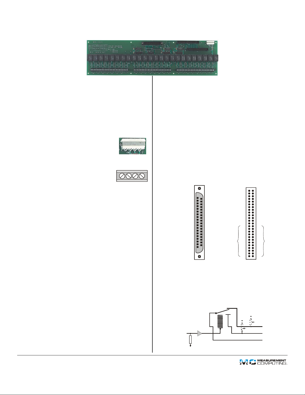
P22
CIO-ERB24
37 RELAY 1
36 RELAY 2
35 RELAY 3
34 RELAY 4
33 RELAY 5
32 RELAY 6
31 RELAY 7
30 RELAY 8
29 RELAY 17
28 RELAY 18
27 RELAY 19
26 RELAY 20
25 RELAY 21
24 RELAY 22
23 RELAY 23
22 RELAY 24
21 GND
20 NC
NC 19
18
17
16
15
14
13
12
GND 11
RELAY 9 10
RELAY 11 8
RELAY 12 7
RELAY 13 6
RELAY 14 5
RELAY 15 4
RELAY 16 3
NC 2
NC 1
NC
NC
NC
NC
NC
NC
NC
37-pin connector (P19)
50-pin connector labeled “IN” (P20)
GND 50
RELAY 17 48
RELAY 16 46
RELAY 21 44
RELAY 23 42
RELAY 9 40
RELAY 11 38
RELAY 13 36
RELAY 15 34
RELAY 1 32
RELAY 3 30
RELAY 5 28
RELAY 7 26
24
22
20
18
16
14
12
10
8
6
4
2
49
47 RELAY 18
45 RELAY 20
43 RELAY 22
41 RELAY 24
39 RELAY 10
37 RELAY 12
35 RELAY 14
33 RELAY 16
31 RELAY 2
29 RELAY 4
27 RELAY 6
25 RELAY 8
23
21
19
17
15
13
11
9
7
5
3
1
Map to OUT pins 26-50
Map to OUT pins 25-49
User-installed pull-up/down
resistor option (R1-R48)
Screw
terminals
C
NO NC
Output from
DIO board
Buffer/
driver
2.2 k
pull-down
resistor
3 per relay
Resistor Networks
RN1 - RN3
R1-R47 (odd)
GND
+5
GND
+5
R2-R48 (even)
NO C NC
Typical channel
24 Electromechanical (Form C) Relays
Functional Description
The CIO-ERB24 is a 24-channel relay accessory for
Measurement Computing Corporation (MCC) digital I/O
boards. The CIO-ERB24 provides 24 SPDT FORM C relays.
Powered from the PC
The CIO-ERB24 does not require 110 VAC
power. It runs on the computer's 5V power supply
or an external 5V supply. Power is connected
through a four-pin MOLEX connector.
Screw Terminal Wiring
The CIO-ERB24 has screw terminals for
connecting your field wiring to the relays.
Each relay has three terminals: COMMON,
NORMALLY OPEN and NORMALLY CLOSED.
The screw terminals are high-quality jaw types that do not
bind when removing wires. Use 12-22 AWG wire gauge.
The screw terminal/module numbers correspond to 8255 ports:
1 to 8 correspond to PORTA bits 0 to 7
9 to 16 correspond to PORTB bits 0 to 7
17 to 20 correspond to PORTC Low bits 0 to 3
21 to 24 correspond to PORTC High bits 4 to 7
I/O Connectors
The CIO-ERB24 has one 37-pin D type connector and two
50-pin connectors. Use a C50FF-x cable to connect with 48bit DIO boards, such as the PCI-DIO48. Use a C37FF-x cable
to connect with 24-bit DIO boards, such as the USBDIO24/37.
Connect the 37-pin connector (P19) to a compatible MCC
digital I/O board.
OR
Connect the 50-pin connector labeled "IN" (P20) to a
compatible MCC digital I/O board.
If you have a second CIO-ERB24 board that you wish to
drive from the unused digital lines of a 48-bit DIO board,
use a C50FF-x cable from the "OUT" connector (P21) of
the first CIO-ERB24 to the "IN" connector (P20) of the
second CIO-ERB24.
Form C Relays
The CIO-ERB24 has FORM C relays. FORM C relays are single
pole, double throw (SPDT) relays. Each relay has three
terminals.
The center terminal is the COMMON terminal (C). This
terminal is switched between the other two.
The NORMALLY CLOSED terminal (NC) is in contact with
the COMMON terminal whenever the CIO-ERB24 is not
powered up or when the controlling bit of the digital I/O
Buffers and Pull-Downs
The CIO-ERB24 inputs from the digital I/O board are pulled
to a steady state by circuitry on the board, so they do not
randomly open or close on power-up. Also, buffer/ drivers on
board accept signals from simple 8255 type digital I/O boards.
board is at logic low.
The NORMALLY OPEN terminal (NO) is in contact with
the COMMON terminal when the controlling bit is logic
high.
DS CIO-ERB24.doc
Document Revision 5 Copyright © Measurement Computing Corporation
 Loading...