

Page 1
No Connect
PC Ground
PC Ground
PC +5V
INVERT NON-INVERT
S1
37
36
35
34
33
32
31
30
29 RELAY 1
28 RELAY 2
27 RELAY 3
26 RELAY 4
25 RELAY 5
24 RELAY 6
23 RELAY 7
22 RELAY 8
21 GND
20 NC
NC
NC
NC
NC
NC
NC
NC
NC
NC 19
18
17
16
15
14
13
12
GND 11
10
9
8
7
6
5
4
3
NC 2
NC 1
NC
NC
NC
NC
NC
NC
NC
NC
NC
NC
NC
NC
NC
NC
NC
User-installed pull-up/down
resistor option (R1-R16)
Screw
terminals
C
NO NC
Output from
DIO board
Buffer/
driver
2.2 k
pull-down
resistor
3 per relay
R1-R15 (odd)
GND
+5
GND
+5
R2-R16 (even)
Resistor Network RN1
NO C NC
Typical channel
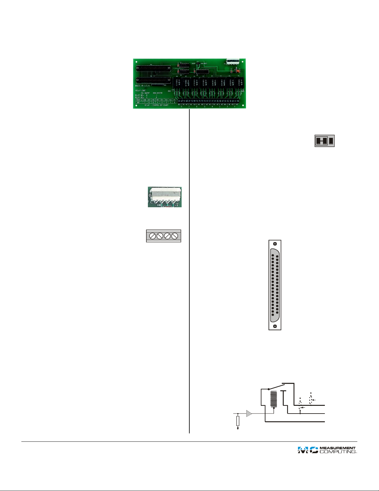
CIO-ERB08
8 Electromechanical (Form C) Relays
Functional Description
The CIO-ERB08 is an 8-channel relay accessory for
Measurement Computing Corporation (MCC) digital I/O
boards. The CIO-ERB08 provides 8 SPDT FORM C relays.
Powered from the PC
The CIO-ERB08 does not require 110 VAC
power. It runs on the computer's 5V power supply
or an external 5V supply. Power is connected
through a four-pin MOLEX connector.
Screw Terminal Wiring
The CIO-ERB08 has screw terminals for
connecting your field wiring to the relays. Each
relay has three terminals: COMMON,
NORMALLY OPEN and NORMALLY CLOSED.
The screw terminals are high-quality jaw types
that do not bind when removing wires. Use 12-22 AWG wire
gauge.
The screw terminal/module numbers correspond to 8255 ports:
1 to 4 correspond to PORTC Low bits 0 to 3
5 to 8 correspond to PORTC High bits 4 to 7
Logic Control
Use jumper (S1) to select inverting or
non-inverting logic to control the
relays. The jumper is set by default
for inverting logic.
When set to INVERT, the relay activates when the output of
the DIO board is high. When set to NON-INVERT, the relay
activates when the output of the DIO board is low.
I/O Connectors
The CIO-ERB08 has two 37-pin connectors (P19 and P20)
that are wired 1:1. Use C37FF-x cables to connect with
compatible MCC digital I/O boards, such as the USBDIO24/37. The 2nd connector is provided to access the
remaining board connections.
Form C Relays
The CIO-ERB08 has FORM C relays. FORM C relays are single
pole, double throw (SPDT) relays. Each relay has three
terminals.
The center terminal is the COMMON terminal (C). This
terminal is switched between the other two.
The NORMALLY CLOSED terminal (NC) is in contact with
the COMMON terminal whenever the CIO-ERB08 is
powered up or when a 0 is written to the controlling bit of
the digital I/O board.
The NORMALLY OPEN terminal (NO) is in contact with
the COMMON terminal when the controlling bit is logic
high and switch S1 is set for inverting logic.
DS CIO-ERB08.doc
Document Revision 4 Copyright © Measurement Computing Corporation
Buffers and Pull-Downs
The CIO-ERB08 inputs from the digital I/O board are pulled
to a steady state by circuitry on the board, so they do not
randomly open or close on power-up. Also, buffer/ drivers on
board accept signals from simple 8255 type digital I/O boards.
 Loading...