

Page 1

CIO-DAS-TEMP
Temperature Input Board
User’s Guide
Revision 4, November, 2000
© Copyright 2000
Page 2

Your new Measurement Computing product comes with a fantastic extra —
Management committed to your satisfaction!
Thank you for choosing a Measurement Computing product—and congratulations! You own the finest, and you can now enjoy
the protection of the most comprehensive warranties and unmatched phone tech support. It’s the embodiment of our mission:
To provide data acquisition hardware and software that will save time and save money.
Simple installations minimize the time between setting up your system and actually making measurements. We offer quick and
simple access to outstanding live FREE technical support to help integrate MCC products into a DAQ system.
Limited Lifetime Warranty: Most MCC products are covered by a limited lifetime warranty against defects in materials or
workmanship for the life of the product, to the original purchaser, unless otherwise noted. Any products found to be defective in
material or workmanship will be repaired, replaced with same or similar device, or refunded at MCC’s discretion. For specific
information, please refer to the terms and conditions of sale.
Harsh Environment Program: Any Measurement Computing product that is damaged due to misuse, or any reason, may be
eligible for replacement with the same or similar device for 50% of the current list price. I/O boards face some harsh
environments, some harsher than the boards are designed to withstand. Contact MCC to determine your product’s eligibility for
this program.
30 Day Money-Back Guarantee: Any Measurement Computing Corporation product may be returned within 30 days of
purchase for a full refund of the price paid for the product being returned. If you are not satisfied, or chose the wrong product by
mistake, you do not have to keep it.
These warranties are in lieu of all other warranties, expressed or implied, including any implied warranty of merchantability or
fitness for a particular application. The remedies provided herein are the buyer’s sole and exclusive remedies. Neither
Measurement Computing Corporation, nor its employees shall be liable for any direct or indirect, special, incidental or
consequential damage arising from the use of its products, even if Measurement Computing Corporation has been notified in
advance of the possibility of such damages.
Trademark and Copyright Information
Measurement Computing Corporation, InstaCal, Universal Library, and the Measurement Computing logo are either trademarks
or registered trademarks of Measurement Computing Corporation. Refer to the Copyrights & Trademarks section on
mccdaq.com/legal for more information about Measurement Computing trademarks. Other product and company names
mentioned herein are trademarks or trade names of their respective companies.
© 2012 Measurement Computing Corporation. All rights reserved. No part of this publication may be reproduced, stored in a
retrieval system, or transmitted, in any form by any means, electronic, mechanical, by photocopying, recording, or otherwise
without the prior written permission of Measurement Computing Corporation.
Notice
Measurement Computing Corporation does not authorize any Measurement Computing Corporation product for use
in life support systems and/or devices without prior written consent from Measurement Computing Corporation.
Life support devices/systems are devices or systems that, a) are intended for surgical implantation into the body, or
b) support or sustain life and whose failure to perform can be reasonably expected to result in injury. Measurement
Computing Corporation products are not designed with the components required, and are not subject to the testing
required to ensure a level of reliability suitable for the treatment and diagnosis of people.
HM CIO-DAS-TEMP.doc
Page 3

Table of Contents
1 INTRODUCTION ................................................................
2 INSTALLATION .................................................................
3 INTERFACING ..................................................................
4 PROGRAMMING AND APPLICATIONS ...........................................
5 THEORY OF OPERATION .......................................................
6 REGISTER MAP .................................................................
7 SPECIFICATIONS ..............................................................
1
1
12.1 SOFTWARE ................................................................
12.2 HARDWARE ................................................................
2
33.1 CONNECTOR DIAGRAM .....................................................
33.2 CONNECTING THE AD592 SENSORS ..........................................
4
44.1 PROGRAMMING LANGUAGES ...............................................
44.2 PACKAGED APPLICATION PROGRAMS .......................................
5
55.1 OVERVIEW .................................................................
65.2 SIGNAL RESOLUTION AND CONVERSION SPEED ..............................
75.3 OPERATION OF THE COUNTERS ..............................................
75.4 LINE NOISE REJECTION .....................................................
9
96.1 CONTROL REGISTERS .......................................................
13
Page 4

This page is blank.
Page 5

1 INTRODUCTION
The CIO-DAS-TEMP is a temperature measurement board desig ned for use with the A D592
semiconductor temperature sensor. Since the AD592 is a current output dev ice, the on-board signal
conditioning is optimized for that sensor. A voltage-to-frequency converter translates the signal from the
sensor into a v alue proportional to tem perature. Functions in the Univ ersal Library convert that
proportional value into a temperature reading on which you can base a control system, or simply log for
later analysis.
The AD592 semiconductor temperature sensor is ideally suited for measurements in the ambient range. If
you are designing an HVAC system, or need to monitor the efficiency of an existing system, the
CIO-DAS-TEMP provides the best value and accuracy in the ambient range. More accurate than
thermocouples and less expensive than RTDs, the AD592 sensor is available through general distribution
or from Measurement Computing Corp. as an individual part or in a stainless steel probe.
Custom Ranges
The CIO-DAS-TEMP is a current input board with a fixed range of 0 to 500 µAmps. The front end may
be customized to allow up to 0 to 20 mA. T he CIO-DAS-TEMP provides up to a full 16 bits of
resolution and will easily reject line noise. If you have a current m easurement application and want a
precisely matched front end, please call our technical support and explain your needs to us.
2 INSTALLATION
2.1 SOFTWARE
There is a bank of switches to set before installing the board in your computer. By far the simplest way to
configure your board is to use the InstaCal
TM
InstaCal
will show you all available options, how to configure the switches to match your application
requirements, and will create a configuration file that your application software (and the Universal
Library) will refer to so the software you use w ill automatically know the exact configuration of the
board.
Please refer to the Software Installation Manual regarding the installation and operation of InstaCal
The following hard copy information is provided as a matter of completeness, and will allow you to set
the hardware configuration of the board if y ou do not have immediate access to InstaCal
computer.
TM
program provided as part of y our software pack age.
TM
and/or your
TM
.
1
Page 6
2.2 HARDWARE
2.2.1 Base I/O Address
The CIO-DAS-TEMP may be set to operate at any one of a range of base addresses. T he
CIO-DAS-TEMP uses eig ht, 8-bit addresses, so the base addresses available are in steps of eig ht. For
example, 300h, 308h, 310h and so on. Table 2-1 of occupied PC addresses below should be
supplemented by information you provide about the addresses used by any other boards or devices
installed in your computer. After all occupied addresses are known, choose an available block of eight
I/O addresses for your CIO-DAS-TEMP. Make sure it is on a 3-bit (8-address) boundary.
Table 2-1. PC I/O Addresses
FUNCTION HEX RANGEFUNCTIONHEX RANGE
EGA 2C0-2CF8237 DMA #1000-00F
EGA2D0-2DF8259 PIC #1020-021
GPIB (AT) 2E0-2E78253 TIMER040-043
SERIAL PORT 2E8-2EF82C55 PPI (XT)060-063
SERIAL PORT 2F8-2FF8742 CONTROLLER (AT)060-064
PROTOTYPE CARD 300-30FCMOS RAM & NMI MASK (AT)070-071
PROTOTYPE CARD310-31FDMA PAGE REGISTERS080-08F
HARD DISK (XT) 320-32F8259 PIC #2 (AT)0A0-0A1
PARALLEL PRINTER378-37FNMI MASK (XT)0A0-0AF
SDLC 380-38F8237 #2 (AT)0C0-0DF
SDLC 3A0-3AF80287 NUMERIC CO-P (AT)0F0-0FF
MDA 3B0-3BBHARD DISK (AT)1F0-1FF
PARALLEL PRINTER3BC-3BFGAME CONTROL200-20F
EGA 3C0-3CFEXPANSION UNIT (XT)210-21F
CGA 3D0-3DFBUS MOUSE238-23B
SERIAL PORT 3E8-3EFALT BUS MOUSE23C-23F
FLOPPY DISK 3F0-3F7PARALLEL PRINTER270-27F
SERIAL PORT3F8-3FFEGA2B0-2BF
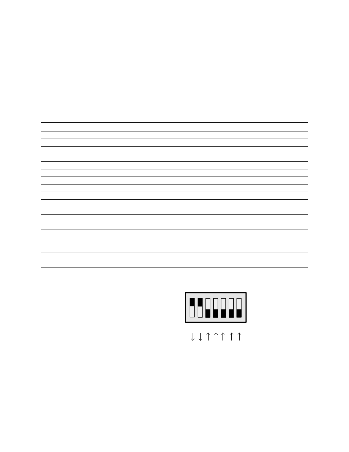
The Base Address is set by a switch on the
CIO-DAS-TEMP labeled ADDRESS. The
CIO-DAS-TEMP uses eight, 8 bit addresses.
The board is set at the factory for address 300h (
768 decimal) as shown here. It is a com mon
address for I/O boards and may already be in use
in your computer. Verify that it, or the address
you choose is available.
Address 300H Shown Below
987654
3
Figure 2-1. Base Address Switches
2
SW
A9
A8
A7
A6
A5
A4
A3
HEX
200
100
80
40
20
10
8
Page 7

3 INTERFACING
The CIO-DAS-TEMP has 32 current inputs desig ned specifically for the AD592 semiconductor-type
temperature sensor.
3.1 CONNECTOR DIAGRAM
The CIO-DAS-TEMP employs the
37-pin, D-type signal connector
common to many I/O boards. It may be
cabled to directly, or throug h a C37FF
cable and screw terminal such as the
CIO-MINI37.
Signal wires from the AD592
temperature sensors should be
connected to the input terminals labeled
TEMP0 through TEMP31.
All the power wires should be
connected in com mon to the +15V DC
power, pin 19.
Please make accurate notes and pay
careful attention to wire connections.
In a large system, finding a misplaced
wire may create hours of work.
+15VDC
TEMP 30
TEMP 28
TEMP 26
TEMP 24
TEMP 22
TEMP 20
TEMP 18
TEMP 16
TEMP 14
TEMP 12
TEMP 10
TEMP 8
TEMP 6
TEMP 4
TEMP 2
TEMP 0
NC
GND
19
18
17
16
15
14
13
12
11
10
9
8
7
6
5
4
3
2
1
37
CAL IN
36
NC
35
TEMP 31
34
TEMP 29
33
TEMP 27
32
TEMP 25
31
TEMP 23
30
TEMP 21
29
TEMP 19
28
TEMP 17
27
TEMP 15
26
TEMP 13
25
TEMP 11
24
TEMP 9
23
TEMP 7
22
TEMP 5
21
TEMP 3
20
TEMP 1
Figure 3-1. 37-Pin Connector
3.2 CONNECTING THE AD592 SENSORS
The AD592 semiconductor temperature sensor produces a current proportional to tem perature. The
sensor employs only two leads, a power lead and the return. The amount of current flowing through the
circuit is proportional to temperature and is the signal measured by the CIO-DAS-TEMP.
The AD592 chip has three leads, two of which are
used. One is the power and one is the return, the
remaining pin is not to be connected and is not
used. The power pins from one or all 32 sensors
are connected to the +15V (pin 19) of the
CIO-DAS-TEMP. The return pin is connected to
the TEMP# of the CIO-DAS-TEMP.
3
VIEW OF SENSOR FROM BOTTOM
WHERE PINS PROTRUDE
IGNAL TO
DAS-TEMP
(-) (+)
Figure 3-2. AD592 Sensor Connections
PIN 2 PIN 1PIN 3
NC
SENSOR POWER
+15V
Page 8

Semiconductor temperature sensors may be purchased from some electronics distributors or directly from
Measurement Computing Corp. An AD592 potted into a stainless steel probe may be purchased from
Measurement Computing Corp. or from other vendors of temperature sensors.
The AD592CN has excellent specifications for ambient temperature measurement (see chapter on
specifications).
In addition, because it is a current-output device, the AD592CN is relatively immune to noise pickup and
IR drops in the signal leads w hen used remotely. I t is reasonably rugged and will withstand supply
irregularities and v ariations or rev ersals up to 20V. Since the A D592s are laser- trimmed, they are
interchangeable and have a high initial accuracy that does not degrade over time
Figure 3-3 shows Measurement Computing’s
SNSR-AD592-PRB6CN (six inch, CN
specifications). T he SNSR-AD592-PRB6CN is
composed of an AD592 connected to two lead
TEMP SIGNAL
BLACK
AD592 SENSOR
PIN 2 PIN 1PIN 3
NC
(-) (+)
SENSOR POWER
RED
wires, inserted into a stainless steel probe and
potted in place.
The unit is waterproof.
There are two wires protruding from the probe.
The RED wire connects to the +15VDC power.
The BLACK wire connects to the TEMP# input
of the CIO-DAS-TEMP.
SENSOR POWER
RED
SENSOR POWER
RED
AD592 SENSOR IN STAILESS STEEL PROBE
TEMP SIGNAL
BLACK
AD592 SENSOR IN STAILESS STEEL PROBE
TEMP SIGNAL
BLACK
SENSOR AT TIP
Figure 3-3. SNSR-AD592-PRB-6-BN Sensor
4 PROGRAMMING AND APPLICATIONS
Although the CI O-DAS-TEMP is part of the larg er DAS family, there is no correspondence between
registers. S oftware written at the reg ister level for the other D AS's will not w ork with the
CIO-DAS-TEMP.
PROGRAMMING LANGUAGES
The UniversalLibrary program provides complete access to the CIO-DAS-TEMP functions from a range
of programming languages; both DOS and Windows. I f you are planning to write prog rams, or would
like to run the example programs for V isual Basic or any other language, please refer to the
UniversalLibrary manual.
PACKAGED APPLICATION PROGRAMS
Many packaged application programs now have drivers for the CIO-DAS-TEMP. I f the package you own
does not appear to hav e drivers for the CI O-DAS-TEMP please fax the package name and the rev ision
number from the install disk s. We will research the package for you and advise by return fax how to
obtain CIO-DAS-TEMP drivers.
4
Page 9

5 THEORY OF OPERATION
5.1 OVERVIEW
The CIO-DAS-TEMP is composed of a C urrent to Voltage (C/V) converter, a Voltage to F requency
(V/F) converter, a channel multiplexer, a sensor excitation power supply and control registers (see Figure
5-1).
The temperature signals,
connected to the channel
multiplexer, are converted
from a current to a voltage
then from a voltage to a
frequency. The frequency is
determined by counting
pulses from the V/F for a
given period. The frequency
is use to calculate the
temperature.
Sensor Power
Supply
AD 31
AD30
AD29
AD28
AD27
...
...
...
AD6
AD5
AD4
AD3
AD2
AD1
AD0
V to F
I to V
32 Channel Multiplexor
V to F Cl ock In
Clock & Pescaler
ISA BUS INTERFACE & CONTROL LOGIC
4MHz
2MHz
Prescaler Out
Figure 5-1. Board Block Diagram
82C54
Counter/Timer Ctrl
IN
CTR 0
V to F Output
Counter
GATE
IN
CTR 1
V to F Pe riod
Counter
GATE
IN
CTR 2
Timer
GATE
Software Trigger
OUT
OUT
OUT
The C/V converter has an output of 0 to 10 volts, which corresponds to the full scale of the current input
or 0 to 500 µA. This input range may be customized at the factory by changing one resistor and one
potentiometer. Please call if you have applications requiring up to 0 to 20 mA input.
The V/F converter has an output of 0 to 2 MHz, which corresponds to the full scale of the voltage input
of 0 to 10 volts. An AD592 sensor will produce frequency in the range of 992 kHz (−25°C) to 1.512
MHz (105°C). Other sensors such as the AD590 (−55°C to 150°C) may be used as well. The equation
for temperature is:
-6
Kelvin = ((10 Volts) * (Fout)) / ((20,000Hz) * (20,000 Ohms) * ( 1 * 10
Amps))
Kelvin = Fout / 4000
5
Page 10

5.2 SIGNAL RESOLUTION AND CONVERSION SPEED
The voltage to frequency converter provides a resolution dependent on the sampling rate. The lower the
sampling rate, the hig her the resolution. Sam pling rates may vary from 25 sam ples per second
(approximately 16-bit resolution) to 4,000 samples per second (approximately 8-bit resolution). For most
temperature measurement applications, rates up to 200 Hz are useful.
The formula for the resolution of the board is:
Full scale range / counts in counter 1
500 µA / (2 <= N <= 65,535 )
The duration of one count is 0.5 µs because the CLK input is 2 MHz
The CIO-DAS-TEMP is constructed of a current-to-voltage front-end and a v oltage-to-frequency
converter. T he V/F converter outputs a frequency that is proportional to the v oltage of its input.
Resolution increases with sample time since the V/F conversion is an average of the signal over the time
of the conversion. The longer the V/F has to settle, the more precise the measurement.
Note that the signal you are measuring should be stable ov er the period of measurement. The
CIO-DAS-TEMP is not desig ned for measurement of v ery rapid changes in temperature. For example,
the maximum sampling rate for the CIO-DAS-TEMP is 200 samples per second. If your temperatures are
changing faster than 200 significant steps per second and you need to precisely trigger and sample that
temperature, you have the wrong product and should call technical support to discuss your application.
The CIO-DAS-TEMP is capable of rejecting line noise when the conversion rate is a multiple of the line
frequency of the power to the PC power supply. Here are the recommended conversion rates and the
accompanying resolutions:
Line FrequencyResolutionRate
60 Hz 0.015 °C*30 Samples/Second
50 Hz0.0125 °C*25 Samples/Second
400 Hz0.1 °C200 Samples/Second
*Note: Exceeds the accuracy of the AD592 sensor.
6
Page 11

5.3 OPERATION OF THE COUNTERS
The 8254 counters 0 and 1 are used to make the frequency measurement of the V/F output. Counter 1 is
clocked by the 2 MHz clock source. A value loaded into counter 1 is used to count down to zero thereby
providing a precise time interval, known as the gate time. For example, if counter 1 were loaded with the
value 5,000 it would count down for 2.5 ms (5,000 / 2,000,000 = 0.0025 sec.).
While counter 1 is counting down, the output pin CTR 1 OUT goes high (a programmable feature
implemented in the Universal Library, or your software). This signal is used to gate counter 0.
Counter 0 is used to accumulate counts from the V/F converter. Recall that the V/F converter produces a
train of pulses proportional to the voltage on its input. At 0 volts the V/F produces zero Hz and at 10
volts, 2 MHz. If the V/F senses 5 volts on its input, it will output pulses at 1 MHz. If counter 1 has been
loaded with a value of 5,000, counter 0 will count pulses for 2.5 ms. 1,000,000 x 0.0025 = 2,500 pulses.
Note that the pulses counted from the V/F are exactly ½ the value loaded into counter 1; the time period
to count pulses. This is a general rule:
Voltage = 10 x (CTR 1 Load / CTR 0 Counts)
In general, a counter 1 period value of 5,000 is a g ood choice and w ill yield good results. The
relationship of degrees Kelvin to counts is:
Kelvin/Count = 500 / Full Scale Count
If the full scale count is 5,000 (as suggested) the relationship is:
500 / 5000 = 0.1K per count
5.4 LINE NOISE REJECTION
V/F converters will reject signal noise that is periodic and of a consistent am plitude because the V/F
converter averages the signal. Sinusoidal noise associated with line frequencies is an example. Since the
signal is averaged (equal areas over and under the mean cancel each other out) the measurement period
must be equal to one cycle, or a multiple of the cycle frequency if noise rejection is desired.
For example, if there is 60 Hz line noise on the signal, the measurement period would have to be:
1/60 = 0.1666
0.16666 x 2,000,000 = 33,333 counts Load this value or a multiple of it into counter 1
For 50 Hz, the calculations are similar. 1/50 x 2,000,000 = 0.02 x 2,000,000 = 40,000
5.4.1 Gate-Time, Resolution and Noise Rejection
The choice of gate time has an affect on the resolution of the measurement, line cycle noise rejection and
the rate over which multiple channels can be scanned. Increasing gate time improves both resolution and
noise rejection but it will decrease the scanning (multiple channel measurement) rate.
7
Page 12

Generally, the choice of gate time is a matter of factoring the desired resolution against the time the
actual measurement takes.
Multiple Channels:
When scanning over multiple channels, the software must explicitly select the next channel in the scan
and start a new conversion. Once the next channel is selected, enough time must be allowed for the new
channel’s current to propagate through the multiplexers and Current-to-Voltage Converter to settle at the
Voltage-to-Frequency converter input. T his is most easily done by doing an extra, or ‘dummy’
conversion, waiting for it to complete and then starting the ‘real’ conversion. Thus, if a gate time of
0.0166 seconds is chosen, the maximum scan rate will be:
Scan Rate = 1 / 2 x [gate time]
= 1 / 2 x [0.0166 seconds]
= 30 samples per second
The following table can be used to select the Gate Count based on either desired maximum sampling rate
or desired resolution.
Desire Max Sample
Rate
Required
ResolutionGate TimeGate Count
Line Frequency
Rejection
60Hz0.015 °C0.01 sec33,33330 samples / sec
50Hz0.0125 °C0.02 sec40,00025 samples / sec
400Hz0.1 °C0.0025 sec5,000200 samples / sec
8
Page 13

6 REGISTER MAP
A base address register controls the beg inning, or 'Base Address' of the I /O addresses occupied by the
control registers of the CIO-DAS-TEMP. In all, eight addresses are occupied. The registers control the
programmable aspects of the CIO-DAS-TEMP performance.
6.1 CONTROL REGISTERS
After a base address has been established, the CIO-DAS-TEMP is controlled by writing to and reading
from the control registers. While it is possible to w rite your own control routines for the
CIO-DAS-TEMP, routines have been written and are available in Universal Library for DOS and
Windows programming languages. Unless you have a specific need to program at the register level, it is
recommended that you use the Universal Library or a packaged application program.
Table 5-1. Control Registers
WRITEREADI/O ADDRESS
Data Load8254 Counter 0 Data ReadBASE + 0
Data Load8254 Counter 1 Data ReadBASE + 1
Data Load8254 Counter 2 Data ReadBASE + 2
8254 Counter Control8254 StatusBASE + 3
Channel Control & StatusChannel & StatusBASE + 4
ClearInterrupt & Prescaler ControlBASE + 5
ReloadNoneBASE + 6
Counter ControlNoneBASE + 7
Register Descriptions
The register descriptions include functions of each bit in each 8-bit register as well as some design and
use descriptions
BASE + 0 Write - Counter 0 Load Register of the 82C54
01234567
Data 0Data 1Data 2Data 3Data 4Data 5Data 6Data 7
Write an initial value of 65,536 to this reg ister after programming the 82C54 control register for CTR 0
to be an event counter. It works as a down-counter, the only choice available.
BASE + 0 Read - Counter 0 Current Count Register of the 82C54
01234567
Data 0Data 1Data 2Data 3Data 4Data 5Data 6Data 7
The total of the V/F output should be read from this register after Counter 1 reaches terminal count
BASE + 1 Write - Counter 1 Load Register of the 82C54
01234567
Data 0Data 1Data 2Data 3Data 4Data 5Data 6Data 7
9
Page 14

First, program the 82C54 control register for CTR 1 to produce a single pulse for the duration of the
count period. Next, load an initial value equal to the period for which counts from the V/F converter will
be totaled See the previous explanation of initial count values for information on what value to load into
this counter. It works as a down-counter, the only choice available.
BASE + 1 Read - Counter 1 Current Count Register of the 82C54
01234567
Data 0Data 1Data 2Data 3Data 4Data 5Data 6Data 7
Will return current count.
BASE + 2 Write - Counter 2 Load Register of the 82C54
01234567
Data 0Data 1Data 2Data 3Data 4Data 5Data 6Data 7
This counter is used to sequence through multiple channels when more than one channel is read. First,
program the 82C54 control register for CTR 2 to function as a rate generator. The register at Base + 5
sets the input (prescaler) frequency for this counter.
Next, load an initial value equal to the number of clock periods between channel readings
BASE + 2 Read - Counter 2 Current Count Register of the 82C54
01234567
Data 0Data 1Data 2Data 3Data 4Data 5Data 6Data 7
Will return current count.
BASE + 3 Write - Control Register of the 82C54
01234567
BCDM0M1M2RW0RW1SC0SC1
The 82C54 counter is described in g reat detail in the Harris or Instel 82C54 data sheet. A brief
description of the control bits follows.
SC1
0 0 Select counter 0
0 1 Select counter 1
1 0 Select counter 2
1 1 Read Command
RW1
0 0 Counter latch
0 1 Read/Write least significant byte of selected counter
1 0 Read/Write most significant byte of selected counter
1 1 Read/Write least significant byte then most significant byte
SC0 Function
RW0 Function
10
Page 15

M1 M0 M0 Function
0 0 0 Program selected counter as event counter, mode 0
0 0 1 Hardware triggered one shot. Pulse is the duration of
the load value
0 1 0 Rate generator. CLK is divided by load value
0 1 1 Square wave. Period equals CLK divided by load value
1 0 0 Software triggered strobe
1 0 1 Hardware triggered strobe
When BCD = 0, the counter counts in binary, 16-bit count. When BCD = 1, the counter counts in
binary-coded-decimal.
BASE + 3 Read - Status Register of the 82C54
01234567
BCDM0M1M2RW0RW1SC0SC1
Will return current status.
BASE + 4 Write - Channel select and mux enable
01234567
CH0CH1CH2CH3CH4XXCHEN
Select channel 0 to 31 in standard binary counting. CHEN enables the mux so that the current channel
sensor is connected to the output of the mux
BASE + 4 Read - Channel, interrupt, calibration switch and EOC status
01234567
CH0CH1CH2CH3CH4CONVCALINT
CH4 through CH0 read back the current channel.
CONV is high when a conversion is in progress and low when conversion is complete, that is when the
counter value in counter 1 has reached zero.
CAL indicates the position of the CAL/NORM switch. NORM = 0, CAL = 1
INT is the status of the interrupt flip flop. It is set whenever conversion is complete (terminal count in
counter 1) whether or not interrupts are enabled. Clear INT by reading Base + 5.
BASE + 5 Write - Interrupt select and trigger mode
01234567
IR0IR1IR2TMREP0P1P2P3
P3 through P0 control a prescalar divider or a 2MHz clock by 4 to 32768 in the steps shown in Table 5-2
below. The output of the prescaler is the input to counter 2, the channel mux sequencer.
11
Page 16

Table 5-2. Prescalar Divider/2 MHz Clock Control Codes
Output FreqP0P1P2P3Output FreqP0P1P2P3
7,812.50001None0000
3,906.251001None1000
1,9530101500,0000100
976.561101250,0001100
488.280011125,0000010
244.14101162,5001010
122.07011131,2500110
61.01111115,6251110
When TMRE = 0, the Prescaler and Counter 2 are disabled. When TMRE = 1, the prescaler and Counter
2 are enabled.
IR2
0 0 0 Disable interrupts
0 0 1 Disable interrupts
0102
0113
1004
1015
1106
1117
BASE + 5 Read - Read bit settings
BASE + 6 Write - Load counter 0
A write to this address loads the v alue 65,535 into counter 0. T his must be done before trig gering a
conversion.
BASE + 7 Not used
IR1 IR0 Hardware IRQ
01234567
IR0IR1IR2TMREP0P1P2P3
12
Page 17

POWER CONSUMPTION
+5V Normal Operation 890 mA Typical 960 mA Max
ANALOG INPUT
Channels 32 Current Input, AD592 Sensor Specific
Range 0 to 500 µΑ
Input Impedance 20 KOhm (nominal)
Resolution
30 S/S 0.015 Deg C (60 Hz Line Frequency)
25 S/S 0.0125 Deg C (50 Hz Line Frequency)
200 S/S 0.1 Deg C (400 Hz Line Frequency)
Current/Temp 1.0 Degrees Kelvin / µAmp
Accuracy ± 0.02%
Linearity Error ± 0.02%
Gain Drift ±75 ppm/°C
V/F Converter AD652
Calibration 0 to 5V (pin 37) @ 10,000 KOhm Input Impedance
7 SPECIFICATIONS
COUNTERS
Counter Type 82C54 Three 16-Bit Down-counters, 10 MHz Max Input
Prescaler 2 MHz divided by 14 programmable steps
Interrupts 2 through 7 Programmable
ENVIRONMENTAL
Operating Range 0 to 60°C
Storage Range −40 to 100°C
Humidity 0 to 90% non-condensing
SENSORS
AD592 Sensor CN Suffix BN Suffix
Temp Range −25 to 105°C −25 to 105°C
Accuracy at range 0 to 70°C, ± 0.8°C 0 to 70°C, ± 1.5°C
−25 to 105 °C, ± 1.0°C −25 to 105°C, ± 2.0°C
Temperature drift ±25 ppm/°C ±25 ppm/°C
Storage Range −45 to 125C −45 to 125°C
13
Page 18

For for Notes.
14
Page 19

EC Declaration of Conformity
We, Measurement Computing Corp., declare under sole responsibility that the product:
Temperature Input BoardCIO-DAS-TEMP
DescriptionPart Number
to which this declaration relates, meets the essential requirements, is in conformity with, and CE marking
has been applied according to the relevant EC Directives listed below using the relevant section of the
following EC standards and other normative documents:
EU EMC Directive 89/336/EEC
EU 55022 C lass B
technology equipment.
EN 50082-1
IEC 801-2
IEC 801-3
equipment.
IEC 801-4
Carl Haapaoja, Director of Quality Assurance
: EC generic immunity requirements.
: Electrostatic discharge requirements for industrial process measurement and control equipment.
: Radiated electromagnetic field requirements for industrial process measurements and control
: Electrically fast transients for industrial process measurement and control equipment.
: L imits and methods of measurements of radio in terference characteristics of information
: Essential requirements relating to electromagnetic compatibility.
Page 20

Measurement Computing Corporation
10 Commerce Way
Suite 1008
Norton, Massachusetts 02766
(508) 946-5100
Fax: (508) 946-9500
E-mail: info@mccdaq.com
www.mccdaq.com
 Loading...