

Page 1

CIO-DAS-TC
Specifications
Document Revision 1.1, February, 2010
© Copyright 2010, Measurement Computing Corporation
Page 2
Specifications
A/D converter type
AD652 V/F converter
Number of channels
16 differential thermocouple inputs, 1 CJC input
Programmable ranges
2.5 V to +10 V, 20 mV to +80 mv, 15 mV to +60 mV, 6.25 mV to 25 mV
Voltage gains
1, 125, 166.7, 400
Thermocouple types
J, K, E, T, R, S, B
A/D pacing
Continuous conversions. Software-programmable for 50 Hz, 60 Hz, or 400 Hz
A/D trigger sources
Software-triggered
Data transfer
Single I/O register transfer through dual port RAM
Conversion rates (integrating
time)
50 Hz, 60 Hz, 400 Hz
Software programmable
*Conversion rates
(per channel)
25.0 msec @ 50 Hz typical, 25.5 msec maximum
21.6 msec @ 60 Hz typical, 22.1 msec maximum
7.4 msec @ 400 Hz typical,7.9 msec maximum
*This is the total time to convert the channel, process the data, and provide a
delay to switch the gain and channel.
Linearity error (A/D specs)
±0.05% @ 4 MHz clock
Gain drift (A/D specs)
±75 ppm/°C max
Zero drift (A/D specs)
±50 uV/°C max
Power supply rejection ratio
0.01 %/V
Overvoltage protection
40 V to +55 V
CMRR @ 60 Hz
80 dB minimum
Input leakage current
±80 nA maximum
Input impedance
100 MegOhm minimum
Absolute maximum input
voltage
40 V to +55 V
Isolation to PC
500 V min through DC/DC converter and opto-isolators
Gain
Range
Accuracy (Worst Case)
Resolution
@ 50 Hz
@ 60 Hz
@ 400 Hz
1
2.5 to 10 V
±0.01% of reading ±2.5 mV
312.5 µV
375 µV
2.5 mV
125
20 to 80 mV
±0.01% of reading ±20 µV
2.5 µV
3.0 µV
20.0 µV
166.7
15 to 60 mV
±0.01% of reading ±15 µV
1.88 µV
2.25 µV
15.0 µV
400
6.25 to 25 mV
±0.02% of reading ±6.25 µV
0.781 µV
0.938 µV
6.25 µV
Typical for 25 °C unless otherwise specified.
Specifications in italic text are guaranteed by design.
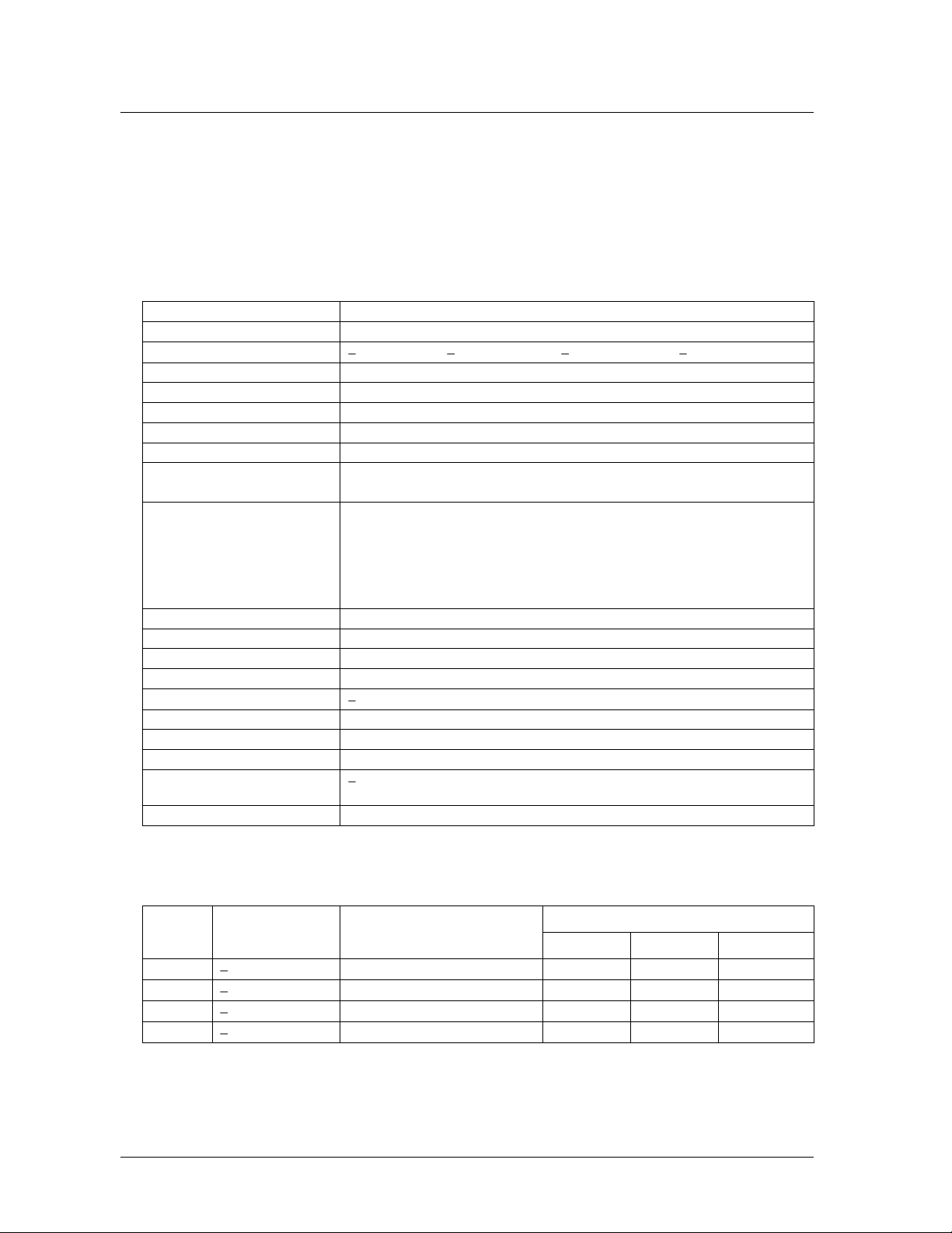
Analog input
Table 1. Analog input specifications
Accuracy and resolution
Table 2. Accuracy and resolution (voltage measurements)
1
Page 3

Specifications CIO-DAS-TC
TC Type
Range
Accuracy (Worst Case)
Resolution
@ 50Hz
@ 60Hz
@ 400Hz
J
0 to 750 °C
±0.5 °C
0.05 °C
0.05 °C
0.40 °C
K
200 to 1250 °C
±1.4 °C
0.04 °C
0.05 °C
0.40°C
E
200 to 900 °C
±1.1 °C
0.03 °C
0.04 °C
0.25 °C
T
200 to 350 °C
±0.9 °C
0.03 °C
0.04 °C
0.25 °C
R
0 to 1450 °C
±2.3 °C
0.06 °C
0.07 °C
0.44 °C
S
0 to 1450 °C
±2.3 °C
0.06 °C
0.08 °C
0.52 °C
B
0 to 1700 °C
±3.0 °C
0.07 °C
0.08 °C
0.54 °C
Averaging
Moving average, 1 to 16 samples, software-selectable
Calibration
Calibration is performed with each channel scan to remove offset and gain error.
CJC channel is also measured with each calibration.
Processor reset
On power-up, watchdog timeout, or software command. Processor boots within one
second of reset. Active low.
Watchdog timer
1.6 seconds nominal. Processor generates watchdog disable signal after boot-up.
Temperature units
Programmable for conversion to C or F
Interrupts
2, 3, 4, 5, 6, or 7
Interrupt enable
Programmable
Interrupt sources
Dual port RAM when the processor mailbox has data.
Frequency
32 MHz
Frequency accuracy
100 ppm
CJC type
AD592CN
Configuration
CJC centered in an isothermal block on which the screw terminals have been
mounted.
Channels
16 (plus CJC output)
@ 25 °C
0.3 °C typical, 0.5 °C maximum
25 °C to +105 °C
0.5 °C typical, 1.0 °C maximum
Table 3. Accuracy and resolution (Thermocouple measurements, not including CJC errors)
Miscellaneous
Table 4. Miscellaneous specifications
Crystal Oscillator
CIO-STA-TC adapter
Calibration error
Table 5. Crystal oscillator specifications
Table 6. CIO-STA-TC adapter specifications
Table 7. Calibration error specifications
2
Page 4

Specifications CIO-DAS-TC
25 °C to +105 °C
0.1 °C typical, 0.35 °C maximum
Temperature coefficient
1 µA/°C typical
Long term stability
0.1 °C / month
Open thermocouple detect
On/off switch selectable for each channel, full scale reading
+5 V operating
887 mA typical, 1441 mA maximum
Operating temperature range
0 to 50 °C
Storage temperature range
20 to 70 °C
Humidity
0 to 90% non-condensing
Connector type
37-pin D-type
Compatible cable
C37FFS-x
Compatible accessory product
(with C37FFS-x cable)
CIO-STA-TC screw terminal adapter board
None
CH14 HI
CH7 LO
CH13 LO
CH13 HI
CH11 LO
CH11 HI
CH9 LO
CH9 HI
CH7 HI
CH5 LO
CH5 HI
CH3 LO
CH3 HI
CHh1 LO
CH1 HI
+15V Isolated Voltage Source
CH15 LO
CH14 LO
Analog Ground
CH12 LO
CH12 HI
CH10 LO
CH10 HI
CH8 LO
CH8 HI
CH6 LO
CH6 HI
CH4 LO
CH4 HI
CH2 LO
CH2 HI
CH0 LO
Linearity error
Table 8. Linearity error specifications
Power consumption
Table 9. Power consumption specifications
Environmental
Table 10. Environmental specifications
Main connector and pin-out
Table 11. Main connector specifications
3
Page 5

CIO-DAS-TC-spec.doc
Measurement Computing Corporation
16 Commerce Boulevard,
Middleboro, Massachusetts 02346
(508) 946-5100
Fax: (508) 946-9500
E-mail: info@mccdaq.com
www.mccdaq.com
 Loading...