

Page 1
Page 2

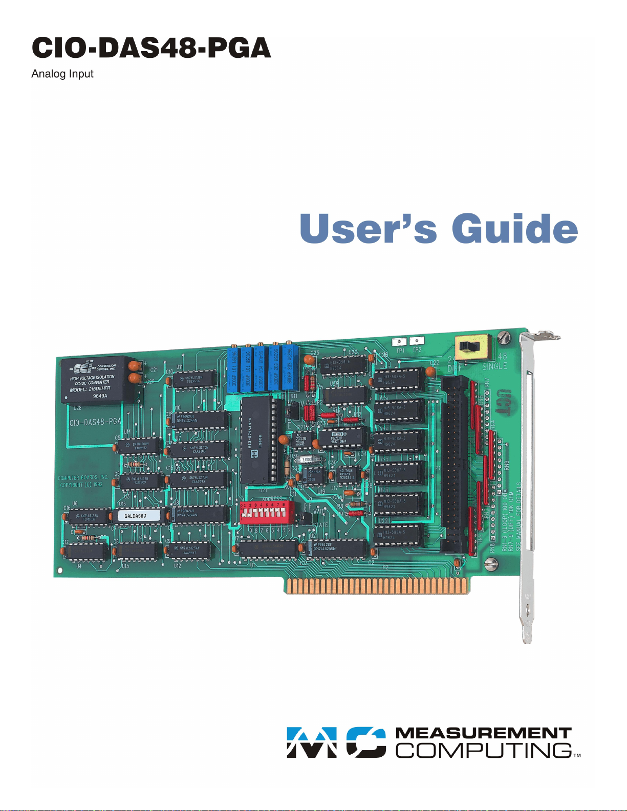
CIO-DAS48-PGA
Analog Voltage Input
User’s Guide
Document Revision 6, January, 2011
© Copyright 2011, Measurement Computing Corporation
Page 3

HM CIO-DAS48-PGA.doc
Your new Measurement Computing product comes with a fantastic extra —
Management committed to your satisfaction!
Thank you for choosing a Measurement Computing product—and congratulations! You own the finest, and you can now enjoy
the protection of the most comprehensive warranties and unmatched phone tech support. It’s the embodiment of our mission:
To provide PC-based data acquisition hardware and software that will save time and save money.
Simple installations minimize the time between setting up your system and actually making measurements. We offer quick and
simple access to outstanding live FREE technical support to help integrate MCC products into a DAQ system.
Limited Lifetime Warranty: Most MCC products are covered by a limited lifetime warranty against defects in materials or
workmanship for the life of the product, to the original purchaser, unless otherwise noted. Any products found to be defective in
material or workmanship will be repaired, replaced with same or similar device, or refunded at MCC’s discretion. For specific
information, please refer to the terms and conditions of sale.
Harsh Environment Program: Any Measurement Computing product that is damaged due to misuse, or any reason, may be
eligible for replacement with the same or similar device for 50% of the current list price. I/O boards face some harsh
environments, some harsher than the boards are designed to withstand. Contact MCC to determine your product’s eligibility for
this program.
30 Day Money-Back Guarantee: Any Measurement Computing Corporation product may be returned within 30 days of
purchase for a full refund of the price paid for the product being returned. If you are not satisfied, or chose the wrong product by
mistake, you do not have to keep it.
These warranties are in lieu of all other warranties, expressed or implied, including any implied warranty of merchantability or
fitness for a particular application. The remedies provided herein are the buyer’s sole and exclusive remedies. Neither
Measurement Computing Corporation, nor its employees shall be liable for any direct or indirect, special, incidental or
consequential damage arising from the use of its products, even if Measurement Computing Corporation has been notified in
advance of the possibility of such damages.
3
Page 4

Trademark and Copyright Information
TracerDAQ, Universal Library, Measurement Computing Corporation, and the Measurement Computing logo are either
trademarks or registered trademarks of Measurement Computing Corporation.
Windows, Microsoft, and Visual Studio are either trademarks or registered trademarks of Microsoft Corporation
LabVIEW is a trademark of National Instruments.
CompactFlash is a registered trademark of SanDisk Corporation.
XBee and XBee-PRO are trademarks of MaxStream, Inc.
All other trademarks are the property of their respective owners.
Information furnished by Measurement Computing Corporation is believed to be accurate and reliable. However, no
responsibility is assumed by Measurement Computing Corporation neither for its use; nor for any infringements of patents or
other rights of third parties, which may result from its use. No license is granted by implication or otherwise under any patent or
copyrights of Measurement Computing Corporation.
All rights reserved. No part of this publication may be reproduced, stored in a retrieval system, or transmitted, in any form by
any means, electronic, mechanical, by photocopying, recording, or otherwise without the prior written permission of
Measurement Computing Corporation.
Notice
Measurement Computing Corporation does not authorize any Measurement Computing Corporation product for use
in life support systems and/or devices without prior written consent from Measurement Computing Corporation.
Life support devices/systems are devices or systems which, a) are intended for surgical implantation into the body,
or b) support or sustain life and whose failure to perform can be reasonably expected to result in injury.
Measurement Computing Corporation products are not designed with the components required, and are not subject
to the testing required to ensure a level of reliability suitable for the treatment and diagnosis of people.
4
Page 5

Table of Contents
Preface
About this User's Guide ....................................................................................................................... 6
What you will learn from this user's guide ......................................................................................................... 6
Conventions in this user's guide ......................................................................................................................... 6
Where to find more information ......................................................................................................................... 6
Chapter 1
Introducing the CIO-DAS48-PGA ......................................................................................................... 7
Overview: CIO-DAS48-PGA features ............................................................................................................... 7
Software features ................................................................................................................................................ 7
Chapter 2
Installing the CIO-DAS48-PGA ............................................................................................................. 8
What comes with your CIO-DAS48-PGA shipment? ........................................................................................ 8
Hardware .......................................................................................................................................................................... 8
Additional documentation .................................................................................................................................. 8
Optional components .......................................................................................................................................... 8
Unpacking the CIO-DAS48-PGA ...................................................................................................................... 9
Installing the software ........................................................................................................................................ 9
Configuring the CIO-DAS48-PGA .................................................................................................................... 9
Base address...................................................................................................................................................................... 9
Wait state .........................................................................................................................................................................10
Input type (V-I) ................................................................................................................................................................10
DIFF/SINGLE .................................................................................................................................................................11
Installing the CIO-DAS48-PGA ....................................................................................................................... 11
Connecting the board for I/O operations .......................................................................................................... 11
Connectors, cables – main I/O connector ........................................................................................................................11
Field wiring, signal termination, and conditioning ..........................................................................................................12
Chapter 3
Functional Details ............................................................................................................................... 13
Single ended inputs ..........................................................................................................................................................13
Differential inputs ............................................................................................................................................................13
Modified differential ........................................................................................................................................................13
Current loop measurements .............................................................................................................................. 13
Chapter 4
Specifications ...................................................................................................................................... 15
Analog input ..................................................................................................................................................... 15
Power consumption .......................................................................................................................................... 15
Environmental .................................................................................................................................................. 16
Main connector and pin out .............................................................................................................................. 16
5
Page 6
About this User's Guide
What you will learn from this user's guide
This user's guide explains how to install, configure, and use the CIO-DAS48-PGA board so that you get the
most out of its analog input features. This user's guide also refers you to related documents available on our
web site, and to technical support resources.
Conventions in this user's guide
The following conventions are used in this manual to convey special information:
For more information on …
Text presented in a box signifies additional information and helpful hints related to the subject matter you are
reading.
Caution! Shaded caution statements present information to help you avoid injuring yourself and others,
damaging your hardware, or losing your data.
Preface
< : > Angle brackets that enclose numbers separated by a colon signify a range of numbers, such as those assigned
to registers, bit settings, etc.
bold text Bold text is used for the names of objects on the screen, such as buttons, text boxes, and check boxes. For
example:
1. Insert the disk or CD and click the OK button.
italic text Italic text is used for the names of manuals and help topic titles, and to emphasize a word or phrase. For
example:
The InstaCal installation procedure is explained in the Quick Start Guide.
Never touch the exposed pins or circuit connections on the board.
Where to find more information
For additional information relevant to the operation of your hardware, refer to the Documents subdirectory
where you installed the MCC DAQ software (C:\Program Files\Measurement Computing\DAQ by default), or
search for your device on our website at www.mccdaq.com.
If you need to program at the register level in your application, refer to the Register Map for the CIO-DAS48-
PGA and CIO-DAS48-I. This document is available on our website at
www.mccdaq.com/registermaps/RegMapCIO-DAS48-PGA-I.pdf.
6
Page 7

Chapter 1
Introducing the CIO-DAS48-PGA
Overview: CIO-DAS48-PGA features
The CIO-DAS48-PGA provides 48 single-ended analog inputs or 24 differential inputs. The input mode is
switch-selectable. Input ranges are software-selectable as either bipolar or unipolar:
Bipolar: ±10 V, ±5 V, ±2.5 V, ±1.25 V, and ±0.625 V
Unipolar: 0 to 10 V, 0 to 5 V, 0 to 2.5 V, and 0 to 1.25 V
In differential mode, up to three optional 10 K SIPs can be installed to provide ground reference to the CH LO
inputs. The SIPs are installed in banks of 8 inputs each.
An optional current measurement conversion kit (MCC part number CIO-DAS48-ISIP) is available for
converting the 24 differential voltage measurements inputs into 24 current measurement inputs. The kit
contains six, four-resistor-SIPs that you install on the board. You set the board's input type to current with an
on-board jumper.
A DC/DC converter supplies stable ±15 V power to the analog circuitry. It is possible to construct the board
without the DC/DC converter. This reduces the cost but limits the ranges of analog inputs. It is available with
orders of 10 or more units.
You can enable a wait state generator with an on-board jumper.
Software features
For information on the features of InstaCal and the other software included with your CIO-DAS48-PGA, refer
to the Quick Start Guide that shipped with your device.
7
Page 8

Installing the CIO-DAS48-PGA
What comes with your CIO-DAS48-PGA shipment?
The following items are shipped with the CIO-DAS48-PGA.
Hardware
CIO-DAS48-PGA
Chapter 2
Additional documentation
In addition to this hardware user's guide, you should also receive the Quick Start Guide (available in PDF at
www.mccdaq.com/PDFmanuals/DAQ-Software-Quick-Start.pdf). This booklet supplies a brief description of
the software you received with your CIO-DAS48-PGA and information regarding installation of that software.
Please read this booklet completely before installing any software or hardware.
Optional components
You can also order the following MCC product to use with your CIO-DAS48-PGA.
C50FF-x cable
Signal termination and conditioning accessories
MCC provides signal conditioning and termination products for use with the CIO-DAS48-PGA. Refer to
Field wiring, signal termination, and conditioning on page 12 for a complete list of compatible accessory
products.
8
Page 9

CIO-DAS48-PGA User's Guide Installing the CIO-DAS48-PGA
Switch/jumper description
Default setting
Base address DIP switch
300h (768 decimal)
Wait State jumper
Off (disabled)
DIFF/SINGLE (input mode) switch
"48 Single" position
Mode V-I jumper (voltage or current type)
"V" (voltage)
Unpacking the CIO-DAS48-PGA
As with any electronic device, you should take care while handling to avoid damage from static
electricity. Before removing the CIO-DAS48-PGA from its packaging, ground yourself using a wrist strap or
by simply touching the computer chassis or other grounded object to eliminate any stored static charge.
If any components are missing or damaged, notify Measurement Computing Corporation immediately by
phone, fax, or e-mail:
Phone: 508-946-5100 and follow the instructions for reaching Tech Support.
Fax: 508-946-9500 to the attention of Tech Support
Email: techsupport@mccdaq.com
Installing the software
Refer to the Quick Start Guide for instructions on installing the software on the Measurement Computing Data
Acquisition Software CD. This booklet is available in PDF at www.mccdaq.com/PDFmanuals/DAQ-Software-
Quick-Start.pdf.
Configuring the CIO-DAS48-PGA
The CIO-DAS48-PGA has a base address switch, an input mode switch, an input type jumper, and a wait state
jumper which you must set before installing the board in your computer. Configure the input type jumper only
if you have the voltage to current input conversion kit.
The InstaCal calibration and test program included with the CIO-DAS48-PGA will show you how to set the
switches and jumpers. Run InstaCal before you open your computer and install the board. The CIO-DAS48PGA is shipped with the factory-default settings listed below.
Factory-configured default settings
Before installing the CIO-DAS48-PGA, verify that the board is configured with the settings that you want.
Review the following information to change the default configuration of a jumper or switch on the CIODAS48-PGA board.
Base address
Before you install the CIO-DAS48-PGA in your computer, set the base address by using the dip switch labeled
ADDRESS located on the board. The easiest way to set the base address switch is to let InstaCal show you the
correct settings. However, if are already familiar with setting ISA base addresses, you may use the base address
switch description below to guide your base address selection.
Unless there is already another board in your system using address 300 hex (768 decimal), leave the switches as
they are set at the factory. The example shown in Figure 1 shows the settings for the factory-default base
address of 300 hex.
9
Page 10

CIO-DAS48-PGA User's Guide Installing the CIO-DAS48-PGA
SW
A9
A8
A7
A6
A5
A4
A3
A2
HEX
200
100
80
40
20
10
08
04
9 8 7 6 5 4 3 29 8 7 6 5 4 3 2
O
N
O
F
F
WAIT STATE
M
O
D
E
V
M
O
D
E
I
Figure 1. Base address switches
In the default configuration shown in Figure 1, addresses 9 and 8 are DOWN, and all others are UP.
Address 9 = 200 hex (512 decimal) and address 8 = 100 hex (256 decimal); when added together they equal
300 hex (768 decimal).
Disregard the numbers printed on the switch
When setting the base address, refer to the numbers printed in white on the printed circuit board.
Wait state
Enable the wait state jumper if you have a computer with an I/O bus transfer rate which is too fast for the CIODAS48-PGA, or if the board fails sporadically in random ways.
To enable the wait state, set the jumper to the ON position. This jumper is OFF by default. Enabling the wait
state causes the personal computer's bus transfer rate to slow down whenever CIO-DAS48-PGA is written to or
read from. This jumper is shown in Figure 2 configured for OFF (wait state is disabled).
Figure 2. Wait state jumper
Input type (V-I)
The jumper labeled MODE V-I sets the input type to either voltage (V) or current (I) (Figure 3). Move the
jumper from V to I only if you have installed the CIO-DAS48-ISIP kit.
Figure 3. Mode V-I jumper
10
Page 11

CIO-DAS48-PGA User's Guide Installing the CIO-DAS48-PGA
48
SINGLE
24
DIFF
Connector type
50-pin header connector
Compatible cable
C50FF-x
Compatible accessory products with
the C50FF-x cable
CIO-MINI50
CIO-SPADE50
DIFF/SINGLE
The differential/single ended mode switch (Figure 4) sets board logic for 48 single-ended channels (48 SINGLE
position) or 24 differential channels (24 DIFF position). If the board is configured for current measurements, set
the V-I jumper to I, and then set the input mode switch to 24 DIFF.
In voltage mode, (V-I jumper "V" position), the board can be used for either single-ended or differential
voltage measurements.
Figure 4. Input mode switch
Installing the CIO-DAS48-PGA
After you configure the board's switches and jumpers, you can install the CIO-DAS48-PGA into your
computer. To install your board, follow the steps below.
Install the MCC DAQ software before you install your board
The driver needed to run your board is installed with the MCC DAQ software. Therefore, you need to install
the MCC DAQ software before you install your board. Refer to the Quick Start Guide for instructions on
installing the software.
1. Turn your computer off, open it up, and insert your board into an available ISA slot.
2. Close your computer and turn it on.
3. To test your installation and configure your board, run the InstaCal utility you installed in the previous
section. Refer to the Quick Start Guide that came with your board www.mccdaq.com/PDFmanuals/DAQ-
Software-Quick-Start.pdf for information on how to initially set up and load InstaCal.
Connecting the board for I/O operations
Connectors, cables – main I/O connector
The table below lists the board connector, applicable cables, and compatible accessory products.
Board connector, cables, and accessory equipment
Information on signal connections
General information regarding signal connection and configuration is available in the Guide to Signal
Connections (available at www.mccdaq.com/signals/signals.pdf).
11
Page 12

CIO-DAS48-PGA User's Guide Installing the CIO-DAS48-PGA
LLGND 50
CH 47 IN 48
CH 46 IN 46
CH 45 IN 44
CH 44 IN 42
CH 43 IN 40
CH 42 IN 38
CH 41 IN 36
CH 40 IN 34
CH 39 IN 32
CH 38 IN 30
CH 37 IN 28
CH 36 IN 26
CH 35 IN 24
CH 34 IN 22
CH 33 IN 20
CH 32 IN 18
CH 31 IN 16
CH 30 IN 14
CH 29 IN 12
CH 28 IN 10
CH 27 IN 8
CH 26 IN 6
CH 25 IN 4
CH 24 IN 2
49 LLGND
47 CH 23 IN
45 CH 22 IN
43 CH 21 IN
41 CH 20 IN
39 CH 19 IN
37 CH 18 IN
35 CH 17 IN
33 CH 16 IN
31 CH 15 IN
29 CH 14 IN
27 CH 13 IN
25 CH 12 IN
23 CH 11 IN
21 CH 10 IN
19 CH 9 IN
17 CH 8 IN
15 CH 7 IN
13 CH 6 IN
11 CH 5 IN
9 CH 4 IN
7 CH 3 IN
5 CH 2 IN
3 CH 1 IN
1 CH 0 IN
Single-ended mode
LLGND 50
CH 23 IN LO 48
CH 22 IN LO 46
CH 21 IN LO 44
CH 20 IN LO 42
CH 19 IN LO 40
CH 18 IN LO 38
CH 17 IN LO 36
CH 16 IN LO 34
CH 15 IN LO 32
CH 14 IN LO 30
28
26
24
22
20
18
16
14
12
10
8
6
4
2
CH 13 IN LO
CH 12 IN LO
CH 11 IN LO
CH 10 IN LO
CH 9 IN LO
CH 8 IN LO
CH 7 IN LO
CH 6 IN LO
CH 5 IN LO
CH 4 IN LO
CH 3 IN LO
CH 2 IN LO
CH 1 IN LO
CH 0 IN LO
49 LLGND
47 CH 23 IN HI
45 CH 22 IN
43 CH 21 IN
41 CH 20 IN
39 CH 19 IN
37 CH 18 IN
35 CH 17 IN
33 CH 16 IN
31 CH 15 IN
29 CH 14 IN
27 CH 13 IN
25 CH 12 IN
23 CH 11 IN
21 CH 10 IN
19 CH 9 IN
17 CH 8 IN
15 CH 7 IN
13 CH 6 IN
11 CH 5 IN
9 CH 4 IN
7 CH 3 IN
5 CH 2 IN
3 CH 1 IN
1 CH 0 IN
HI
HI
HI
HI
HI
HI
HI
HI
HI
HI
HI
HI
HI
HI
HI
HI
HI
HI
HI
HI
HI
HI
HI
Differential mode
The red stripe
identifies pin # 1
50-pin Female
IDC connector
50-pin Female
IDC Connector
1
2
49
50
2
50
1
49
Pinout – main I/O connector
The CIO-DAS48-PGA I/O connector is a standard 50-pin header connector that is accessible from the rear of
the computer through the expansion backplate.
Figure 5. I/O connector pin-out
Current connections are made between CH# HI and CH# LOW. The positive terminal of the current to be
measured must be connected to CH# HI (refer to Current loop measurements on page 13).
Cabling
Field wiring, signal termination, and conditioning
You can use the following cabling, screw termination, and signal conditioning products with the CIO-DAS48PGA.
CIO-MINI50 – 50-pin screw terminal board
CIO-SPADE50 — 16" X 4" termination panel which mates with both 37-pin and 50-pin connectors.
Figure 2-1. C50FF-x cable
12
Page 13

Chapter 3
Functional Details
Single ended inputs
Single-ended inputs are two-wire connections between the signal source and the A/D board. A single wire
carries the signal, and is connected from the signal source to Channel n HI. The ground from the signal source
must be connected to LLGND (pins 49 or 50).
Differential inputs
Differential inputs are 3-wire analog hookups consisting of a signal high, signal low and chassis ground. The
signal source high is connected to Channel n HI, the signal source low is connected to Channel n LO, and the
signal source GND is connected to LLGND.
The benefits of differential inputs are the ability to reject noise which affects both signal high and low, and the
ability to compensate for ground loops or potentials between signal low and chassis ground.
Modified differential
Modified differential inputs for voltage measurements provide much of the environmental-noise immunity and
common mode rejection of fully differential inputs with the convenience of a two wire hookup.
Although differential inputs are often preferable to single-ended inputs, there are occasions when the floating
nature of a differential input can prevent making a valid reading. In those cases, the CIO-DAS48-PGA inputs
can be converted to modified differential.
Near the 50-pin connector on the board are positions for optional Single Inline Packages (SIP) of 10 K
resistors. Installing the SIP in RN7, RN8 and RN9 converts the analog inputs from fully differential to modified
differential with a 10 K reference to ground.
Notes: All three sips must be installed. It is not possible to mix channels.
After the SIPs are installed, signal connections require on Signal Source Hi be connected to Channel n HI and
signal source low be connected to Channel n LOW. No connection to LLGND is needed.
Special instructions and solder are packaged with the 10K SIP. Follow the installation instructions carefully and
use the solder provided. Use of other solder, or failure to follow instructions will probably result in a
degradation of the analog input's accuracy and will require out-of-warranty repair.
Current loop measurements
If you are configuring a CIO-DAS48-PGA for current measurements, do the following operations:
1. Remove (clip off) the SIPs from RN7, RN8, and RN9, if installed. These SIPs must not be installed if the
board is to be used for current measurement.
2. Install the resistor "CIO-DAS48-ISIP" kit. Install ISIPs in RN1, RN2, RN3, RN4, RN5, and RN6.
Special instructions and solder are packaged with the CIO-DAS48-ISIP kit. Follow the installation
instructions carefully and use the solder provided. Use of other solder, or failure to follow instructions will
probably result in a degradation of the analog input's accuracy and will require out-of-warranty repair.
13
Page 14

CIO-DAS48-PGA User's Guide Functional Details
The selection of the ISIPs is critical. Variations in either value or tolerance from those supplied in the
CIO-DAS48-ISIP will result in inaccurate measurements.
3. Set the input type jumper to the "I" position (see page Error! Bookmark not defined.).
4. Set the DIFF/SINGLE switch to the "24 DIFF" position (see page 11).
5. Install the board and run the InstaCal calibration procedure for current mode.
After installation, the inputs are committed to current measurement and cannot be used for voltage
measurement.
To restore the inputs to voltage measurement remove the ISIPs (clip off the SIPs). If you want to de-solder
the SIPs, you must return the board to the factory.
If you want to re-install the 10k SIPs in RN7, RN8, and RN9 (to have ―Modified-Differential‖ inputs), you
must return the board to the factory.
It is not possible to install only a portion of the ISIPs and have a mixture of current and voltage inputs. You
must install all six SIPs from the CIO-DAS48-ISIP package, and set the input type jumper to the "I" position.
14
Page 15

Parameter
Specification
A/D converter type
AD574
Resolution
12 bits
Number of channels
48 single-ended, 24 differential (configurable as 24 modified differential via
installation of SIP resistor)
Input type
Voltage input or current input, configurable by jumper and installation of SIP
resistors for current configuration
Input ranges
±10 V, ±5 V, ±2.5 V, ±1.25 V, ±0.625 V, 0 to 10 V, 0 to 5 V, 0 to 2.5 V, 0 to
1.25 V, software selectable
Polarity
Unipolar/Bipolar, software selectable
A/D pacing
Software polled
Data transfer
Software polled
A/D conversion time
25µs
Throughput
20 kS/s, PC dependent
Accuracy
±0.01% of reading ±1 LSB
Differential linearity error
±1 LSB
Integral linearity error
±0.5 LSB
No missing codes guaranteed
12 bits
Gain drift (A/D specs)
±25 ppm/°C
Zero drift (A/D specs)
±10 µV/°C
Common mode range
±10 V
CMRR
72 dB
Input leakage current (@ 25 C)
100 nA
Input impedance
10 Meg Ohms min
Absolute maximum input voltage
±35V
Noise distribution (Rate = 1-10 kHz, Average % +/- 2 bins, Average % +/- 1 bin, Average # bins)
Bipolar
10V 100% / 100% / 3 bins
5V 100% / 98.8% / 4 bins
2.5V 100% / 96.8% / 4 bins
1.25V 100% / 98.2% / 5 bins
0.625V 100% / 99% / 5 bins
Unipolar
10V 100% / 98.6% / 4 bins
5V 100% / 98.8% / 4 bins
2.5V 100% / 97.4% / 4 bins
1.25V 100% / 98.2% / 4 bins
+5 V
620 mA typical, 800 mA max
Specifications
Typical for 25°C unless otherwise specified.
Specifications in italic text are guaranteed by design.
Analog input
Table 1. Analog input specifications
Chapter 4
Power consumption
Table 2. Power consumption specifications
15
Page 16

CIO-DAS48-PGA User's Guide Specifications
Operating temperature range
0 to 50 °C
Storage temperature range
-20 to 70 °C
Humidity
0 to 90% non-condensing
Connector type
50-pin D type connector
Compatible cable
C50FF-x
Compatible accessory products with the
C50FF-x cable
CIO-MINI50
CIO-SPADE50
Pin
Signal name
Pin
Signal name
50
LLGND
49
LLGND
48
CH 47 IN
47
CH 23 IN
46
CH 46 IN
45
CH 22 IN
44
CH 45 IN
43
CH 21 IN
42
CH 44 IN
41
CH 20 IN
40
CH 43 IN
39
CH 19 IN
38
CH 42 IN
37
CH 18 IN
36
CH 41 IN
35
CH 17 IN
34
CH 40 IN
33
CH 16 IN
32
CH 39 IN
31
CH 15 IN
30
CH 38 IN
29
CH 14 IN
28
CH 37 IN
27
CH 13 IN
26
CH 36 IN
25
CH 12 IN
24
CH 35 IN
23
CH 11 IN
22
CH 34 IN
21
CH 10 IN
20
CH 33 IN
19
CH 9 IN
18
CH 32 IN
17
CH 8 IN
16
CH 31 IN
15
CH 7 IN
14
CH 30 IN
13
CH 6 IN
12
CH 29 IN
11
CH 5 IN
10
CH 28 IN
9
CH 4 IN
8
CH 27 IN
7
CH 3 IN
6
CH 26 IN
5
CH 2 IN
4
CH 25 IN
3
CH 1 IN
2
CH 24 IN
1
CH 0 IN
Environmental
Table 3. Environmental specifications
Main connector and pin out
Table 4. Main connector specifications
Table 5. Single-ended mode pin out
16
Page 17

CIO-DAS48-PGA User's Guide Specifications
Pin
Signal name
Pin
Signal name
50
LLGND
49
LLGND
48
CH 23 IN LO
47
CH 23 IN HI
46
CH 22 IN LO
45
CH 22 IN HI
44
CH 21 IN LO
43
CH 21 IN HI
42
CH 20 IN LO
41
CH 20 IN HI
40
CH 19 IN LO
39
CH 19 IN HI
38
CH 18 IN LO
37
CH 18 IN HI
36
CH 17 IN LO
35
CH 17 IN HI
34
CH 16 IN LO
33
CH 16 IN HI
32
CH 15 IN LO
31
CH 15 IN HI
30
CH 14 IN LO
29
CH 14 IN HI
28
CH 13 IN LO
27
CH 13 IN HI
26
CH 12 IN LO
25
CH 12 IN HI
24
CH 11 IN LO
23
CH 11 IN HI
22
CH 10 IN LO
21
CH 10 IN HI
20
CH 9 IN LO
19
CH 9 IN HI
18
CH 8 IN LO
17
CH 8 IN HI
16
CH 7 IN LO
15
CH 7 IN HI
14
CH 6 IN LO
13
CH 6 IN HI
12
CH 5 IN LO
11
CH 5 IN HI
10
CH 4 IN LO
9
CH 4 IN HI
8
CH 3 IN LO
7
CH 3 IN HI
6
CH 2 IN LO
5
CH 2 IN HI
4
CH 1 IN LO
3
CH 1 IN HI
2
CH 0 IN LO
1
CH 0 IN HI
Table 6. Differential mode pin out
17
Page 18

Measurement Computing Corporation
10 Commerce Way
Suite 1008
Norton, Massachusetts 02766
(508) 946-5100
Fax: (508) 946-9500
E-mail: info@mccdaq.com
www.mccdaq.com
 Loading...