

Page 1
Page 2

CIO-CTR05
Counter/Timer Board
User's Guide
Document Revision 6, March, 2010
© Copyright 2010, Measurement Computing Corporation
Page 3

HM CIO-CTR05.doc
Your new Measurement Computing product comes with a fantastic extra —
Management committed to your satisfaction!
Thank you for choosing a Measurement Computing product—and congratulations! You own the finest, and you can now enjoy
the protection of the most comprehensive warranties and unmatched phone tech support. It’s the embodiment of our mission:
To provide PC-based data acquisition hardware and software that will save time and save money.
Simple installations minimize the time between setting up your system and actually making measurements. We offer quick and
simple access to outstanding live FREE technical support to help integrate MCC products into a DAQ system.
Limited Lifetime Warranty: Most MCC products are covered by a limited lifetime warranty against defects in materials or
workmanship for the life of the product, to the original purchaser, unless otherwise noted. Any products found to be defective in
material or workmanship will be repaired, replaced with same or similar device, or refunded at MCC’s discretion. For specific
information, please refer to the terms and conditions of sale.
Harsh Environment Program: Any Measurement Computing product that is damaged due to misuse, or any reason, may be
eligible for replacement with the same or similar device for 50% of the current list price. I/O boards face some harsh
environments, some harsher than the boards are designed to withstand. Contact MCC to determine your product’s eligibility for
this program.
30 Day Money-Back Guarantee: Any Measurement Computing Corporation product may be returned within 30 days of
purchase for a full refund of the price paid for the product being returned. If you are not satisfied, or chose the wrong product by
mistake, you do not have to keep it.
These warranties are in lieu of all other warranties, expressed or implied, including any implied warranty of merchantability or
fitness for a particular application. The remedies provided herein are the buyer’s sole and exclusive remedies. Neither
Measurement Computing Corporation, nor its employees shall be liable for any direct or indirect, special, incidental or
consequential damage arising from the use of its products, even if Measurement Computing Corporation has been notified in
advance of the possibility of such damages.
3
Page 4

Trademark and Copyright Information
TracerDAQ, Universal Library, Measurement Computing Corporation, and the Measurement Computing logo are either
trademarks or registered trademarks of Measurement Computing Corporation.
Windows, Microsoft, and Visual Studio are either trademarks or registered trademarks of Microsoft Corporation
LabVIEW is a trademark of National Instruments.
CompactFlash is a registered trademark of SanDisk Corporation.
XBee and XBee-PRO are trademarks of MaxStream, Inc.
All other trademarks are the property of their respective owners.
Information furnished by Measurement Computing Corporation is believed to be accurate and reliable. However, no
responsibility is assumed by Measurement Computing Corporation neither for its use; nor for any infringements of patents or
other rights of third parties, which may result from its use. No license is granted by implication or otherwise under any patent or
copyrights of Measurement Computing Corporation.
All rights reserved. No part of this publication may be reproduced, stored in a retrieval system, or transmitted, in any form by
any means, electronic, mechanical, by photocopying, recording, or otherwise without the prior written permission of
Measurement Computing Corporation.
Notice
Measurement Computing Corporation does not authorize any Measurement Computing Corporation product for use
in life support systems and/or devices without prior written consent from Measurement Computing Corporation.
Life support devices/systems are devices or systems which, a) are intended for surgical implantation into the body,
or b) support or sustain life and whose failure to perform can be reasonably expected to result in injury.
Measurement Computing Corporation products are not designed with the components required, and are not subject
to the testing required to ensure a level of reliability suitable for the treatment and diagnosis of people.
4
Page 5

Table of Contents
Preface
About this User's Guide ....................................................................................................................... 6
What you will learn from this user's guide ......................................................................................................... 6
Conventions in this user's guide ......................................................................................................................... 6
Where to find more information ......................................................................................................................... 6
Chapter 1
Introducing the CIO-CTR05 .................................................................................................................. 7
Overview: CIO-CTR05 features ......................................................................................................................... 7
Software features ................................................................................................................................................ 7
Chapter 2
Installing the CIO-CTR05 ...................................................................................................................... 8
What comes with your CIO-CTR05 shipment?.................................................................................................. 8
Hardware .......................................................................................................................................................................... 8
Additional documentation .................................................................................................................................. 8
Optional components .......................................................................................................................................... 8
Unpacking the CIO-CTR05 ................................................................................................................................ 9
Installing the software ........................................................................................................................................ 9
Configuring the CIO-CTR05 .............................................................................................................................. 9
Base address switch .......................................................................................................................................................... 9
Interrupt level select jumper ............................................................................................................................................11
Wait state jumper .............................................................................................................................................................11
Installing the CIO-CTR05 ................................................................................................................................ 12
Connecting the board for I/O operations .......................................................................................................... 12
Connectors, cables – main I/O connector ........................................................................................................................12
Pin out – main I/O connector ...........................................................................................................................................13
Cabling.............................................................................................................................................................................13
Field wiring, signal termination, and conditioning ..........................................................................................................13
Chapter 3
Specifications ...................................................................................................................................... 14
Counter ............................................................................................................................................................. 14
Interrupts .......................................................................................................................................................... 14
Digital input / output ........................................................................................................................................ 14
Power consumption .......................................................................................................................................... 15
Environmental .................................................................................................................................................. 15
Main connector and pin out .............................................................................................................................. 15
P1 pin out .........................................................................................................................................................................15
Declaration of Conformity .................................................................................................................. 16
5
Page 6
Preface
About this User's Guide
What you will learn from this user's guide
This user's guide explains how to install, configure, and use the CIO-CTR05 board so that you get the most out
of its counter/timer features. This user's guide also refers you to related documents available on our web site,
and to technical support resources.
Conventions in this user's guide
The following conventions are used in this manual to convey special information:
For more information on …
Text presented in a box signifies additional information and helpful hints related to the subject matter you are
reading.
Caution! Shaded caution statements present information to help you avoid injuring yourself and others,
damaging your hardware, or losing your data.
< : > Angle brackets that enclose numbers separated by a colon signify a range of numbers, such as those assigned
to registers, bit settings, etc.
bold text Bold text is used for the names of objects on the screen, such as buttons, text boxes, and check boxes. For
example:
1. Insert the disk or CD and click the OK button.
italic text Italic text is used for the names of manuals and help topic titles, and to emphasize a word or phrase. For
example:
The InstaCal installation procedure is explained in the Quick Start Guide.
Never touch the exposed pins or circuit connections on the board.
Where to find more information
For additional information relevant to the operation of your hardware, refer to the Documents subdirectory
where you installed the MCC DAQ software (C:\Program Files\Measurement Computing\DAQ by default), or
search for your device on our website at www.mccdaq.com.
If you need to program at the register level in your application, refer to the Register Map for the CIO-CTR05
and CIO-CTR10. This document is available on our website at www.mccdaq.com/registermaps/RegMapCIO-
CTR05_10.pdf.
6
Page 7

Chapter 1
Introducing the CIO-CTR05
Overview: CIO-CTR05 features
The CIO-CTR05 is based on the 9513 counter/timer device. The CIO-CTR05 has one 9513 counter/timer
device. The 9513 device has five independent 16-bit counters (65,536 counts). Each counter has an input
source, count register, load register, hold register, alarm register, output, and gate associated with each counter.
The 9513 is software-programmable for event counting, pulse and frequency measurement, alarm comparisons,
and other input functions. The 9513 can generate frequencies with either complex duty cycles, or with one-shot
and continuous-output modes. You can chain up to five 9513 counters together using software to enable a 32-,
48-, 64-, or 80-bit counter that does not require hardware connections. The gate source and gating functions are
software-programmable.
An eight-bit digital output port provides logic-level control, and can be used to switch solid state relays. An
eight-bit digital input port can be used to sense contact closures and other TTL level signals.
Software features
For information on the features of InstaCal and the other software included with your CIO-CTR05, refer to the
Quick Start Guide that shipped with your device.
7
Page 8
Installing the CIO-CTR05
What comes with your CIO-CTR05 shipment?
The following items are shipped with the CIO-CTR05.
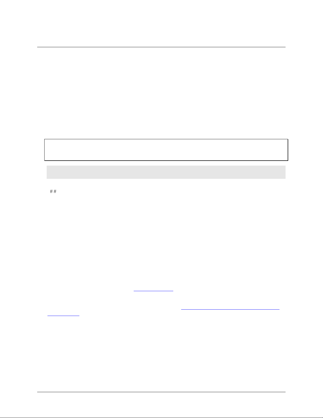
Hardware
CIO-CTR05
Chapter 2
Additional documentation
In addition to this hardware user's guide, you should also receive the Quick Start Guide (available in PDF at
www.mccdaq.com/PDFmanuals/DAQ-Software-Quick-Start.pdf). This booklet supplies a brief description of
the software you received with your CIO-CTR05 and information regarding installation of that software. Please
read this booklet completely before installing any software or hardware.
Optional components
You can also order the following MCC products to use with your CIO-CTR05.
C37FF-x cable
Signal termination and conditioning accessories
MCC provides signal conditioning and termination products for use with the CIO-CTR05. Refer to Field
wiring, signal termination, and conditioning on page 13 for a complete list of compatible accessory
products.
8
Page 9
CIO-CTR05 User's Guide Installing the CIO-CTR05
Jumper/Switch
Description
Default setting
Base address
DIP switch for setting the base address
300h (768 decimal)
Interrupt Level
Jumper to set the IRQ number you want the
interrupt pulse on
X position (no interrupt set)
Wait State
Jumper to enable a wait state
OFF position
Unpacking the CIO-CTR05
As with any electronic device, you should take care while handling to avoid damage from static
electricity. Before removing the CIO-CTR05 from its packaging, ground yourself using a wrist strap or by
simply touching the computer chassis or other grounded object to eliminate any stored static charge.
If any components are missing or damaged, notify Measurement Computing Corporation immediately by
phone, fax, or e-mail:
Phone: 508-946-5100 and follow the instructions for reaching Tech Support.
Fax: 508-946-9500 to the attention of Tech Support
Email: techsupport@mccdaq.com
Installing the software
Refer to the Quick Start Guide for instructions on installing the software on the Measurement Computing Data
Acquisition Software CD. This booklet is available in PDF at www.mccdaq.com/PDFmanuals/DAQ-Software-
Quick-Start.pdf.
Configuring the CIO-CTR05
The CIO-CTR05 has a base address switch, an interrupt level select jumper, and a wait state jumper which you
must set before installing the board in your computer. The InstaCal calibration and test program included with
the CIO-CTR05 will show you how to configure the board. Run InstaCal before you open your computer and
install the board. The CIO-CTR05 is shipped with the factory-default settings listed below.
Factory-configured default settings
Before installing the CIO-CTR05 in the computer, verify that the board is configured with the settings that you
want. Review the following information to change the default configuration of a jumper or switch on the CIOCTR05 board.
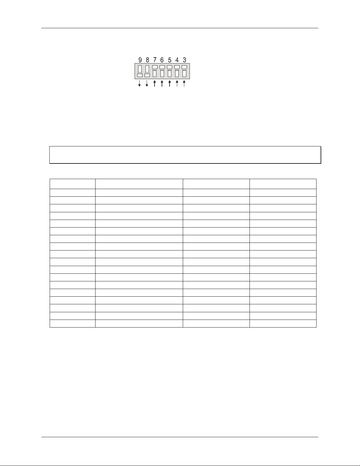
Base address switch
Before you install the CIO-CTR05 in your computer, set the base address by using the dip switch labeled
ADDRESS located on the board.
The easiest way to set the base address switch is to let InstaCal show you the correct settings. However, if are
already familiar with setting ISA base addresses, you may use the base address switch description below to
guide your base address selection.
Unless there is already another board in your system using address 300 hex (768 decimal), leave the switches as
they are set at the factory. The example shown in Figure 1 shows the settings for the factory-default base
address of 300 hex.
9
Page 10
CIO-CTR05 User's Guide Installing the CIO-CTR05
SW
A9
A8
A7
A6
A5
A4
A3
HEX
200
100
80
40
20
10
08
ADDRESS
Hex Range
Function
Hex Range
Function
000-00F
8237 DMA #1
2C0-2CF
EGA
020-021
8259 PIC#1
2D0-2DF
EGA
040-043
8253 Timer
2E0-2E7
GPIB (AT)
060-063
8255 PPI (XT)
2E8-2EF
Serial Port
060-064
8742 Controller (AT)
2F8-2FF
Serial Port
070-071
CMOS RAM & NMI mask (AT)
300-30F
Prototype card
080-08F
DMA page registers
310-31F
Prototype card
0A0-0A1
8259 PIC #2 (AT)
320-32F
Hard disk (XT)
0A0-0AF
NMI mask (XT)
378-37F
Parallel printer
0C0-0DF
8237 #2 (AT)
380-38F
SDLC
0F0-0FF
80287 numeric CO-P (AT)
3A0-3AF
SDLC
1F0-1FF
Hard disk (AT)
3B0-3BB
MDA
200-20F
Game control
3BC-3BB
Parallel printer
210-21F
Expansion unit (XT)
3C0-3CF
EGA
238-23B
Bus mouse
3D0-3DF
CGA
23C-23F
ALT bus mouse
3E8-3EF
Serial port
270-27F
Parallel printer
3F0-3F7
Floppy disk
2B0-2BF
EGA
3F8-3FF
Serial port
Figure 1. Base address switches
In the default configuration shown in Figure 1, addresses 9 and 8 are DOWN, and all others are UP.
Address 9 = 200 hex (512 decimal) and address 8 = 100 hex (256 decimal); when added together they equal
300 hex (768 decimal).
Disregard the numbers printed on the switch
When setting the base address, refer to the numbers printed in white on the printed circuit board.
PC I/O addresses
The CIO-CTR05 Base switch can be set for an address in the range of 000-3E0, so it should not be hard to find
a free address area for your CIO-CTR05. If you are not using IBM prototyping cards, or some other board
which occupies these addresses, then 300-31F HEX are free to use. Addresses not specifically listed, such as
390-39F, are free.
10
Page 11

CIO-CTR05 User's Guide Installing the CIO-CTR05
2 3 4 5 6 7 X
IR1
Name
Description
Name
Description
NMI
Parity
IRQ8
Real Time Clock (AT)
IRQ0 (AT)
Timer
IRQ9
Re-Directed To IRQ2
IRQ1
Keyboard
IRQ10
Unassigned
IRQ2
RESERVED (XT) INT 8-15 (AT)
IRQ11
Unassigned
IRQ3
COM OR SDLC
IRQ12
Unassigned
IRQ4
COM OR SDLC
IRQ13
80287 Numeric CO-P
IRQ5
Hard Disk (AT) LPT (AT)
IRQ14
Hard Disk
IRQ6
Floppy Disk
IRQ15
Unassigned
IRQ7
LPT
O
N
O
F
F
WAIT
STATE
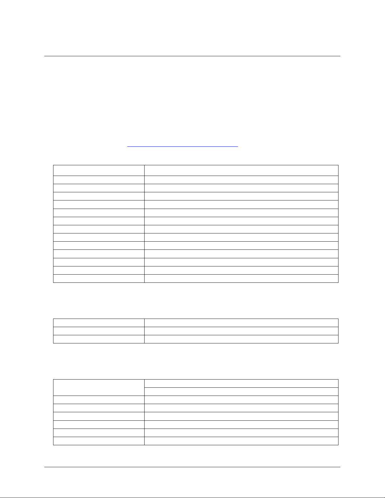
Interrupt level select jumper
Use the Interrupt Level Select jumper located above the PC bus interface (gold pins) to set the IRQ number you
want the interrupt pulse on.
This jumper is set by default with no interrupt level set ("X" position). Interrupts are hardware initiated
software routines and are described in the section on programming.
Figure 2. Interrupt Level Select jumper
Pin 1 (IR INPUT) of the 37-pin connector is an input jumper which maps the interrupt directly onto the PC bus.
The signal to the bus is buffered. The buffer is enabled by a TTL low level on Pin 2 (IR ENABLE).
Hardware interrupts assigned by the PC may be available; refer to the following table. Note that IRQ8 to IRQ15
are AT only.
Wait state jumper
The CIO-CTR05 board has a wait state jumper which you can set to enable an on-board wait state generator. A
wait state is an extra delay injected into the processor's clock via the bus. This delay slows down the processor
when the processor addresses the CIO-CTR05 board so that signals from slow devices (chips) will be valid.
The jumper is shown in Figure 3 configured for OFF (wait state is disabled).
The wait state generator on the CIO-CTR05 is only active when the CIO-CTR05 is being accessed. Your PC
will not be slowed down in general by using the wait state.
Figure 3. Wait State jumper
11
Page 12

CIO-CTR05 User's Guide Installing the CIO-CTR05
Connector type
37-pin male D type
Compatible cables
C37FF-x
Compatible accessory products with
the C37FF-x cable or C37FFS-x cable
CIO-MINI37
CIO-TERMINAL
Installing the CIO-CTR05
After you configure the board's switches and jumpers, you can install the CIO-CTR05 into your computer. To
install your board, follow the steps below.
Install the MCC DAQ software before you install your board
The driver needed to run your board is installed with the MCC DAQ software. Therefore, you need to install
the MCC DAQ software before you install your board. Refer to the Quick Start Guide for instructions on
installing the software.
1. Turn your computer off, open it up, and insert your board into an available ISA slot.
2. Close your computer and turn it on.
3. To test your installation and configure your board, run the InstaCal utility you installed in the previous
section. Refer to the Quick Start Guide that came with your board www.mccdaq.com/PDFmanuals/DAQ-
Software-Quick-Start.pdf for information on how to initially set up and load InstaCal.
Connecting the board for I/O operations
Connectors, cables – main I/O connector
The table below lists the board connector, applicable cables, and compatible accessory products.
Board connector, cables, and accessory equipment
Information on signal connections
General information regarding signal connection and configuration is available in the Guide to Signal
Connections (available at www.mccdaq.com/signals/signals.pdf).
12
Page 13

CIO-CTR05 User's Guide Installing the CIO-CTR05
37 CTR1 GATE
36
35
34
33
32
31
30
29
28
27
26
25
24
23
22
21 DIN STROBE
20 +5V
CTR1 IN
CTR1 OUT
CTR2 OUT
CTR3 OUT
CTR4 OUT
CTR5 OUT
OSC OUT
DIN 0
DIN 1
DIN 2
DIN 3
DIN 4
DIN 5
DIN 6
DIN 7
CTR2 IN 19
18
17
16
15
14
13
12
GND 11
DOUT 0 10
9
8
7
6
5
4
3
IR ENABLE 2
IR INPUT 1
CTR2 GATE
CTR3 IN
CTR3 GATE
CTR4 IN
CTR4 GATE
CTR5 IN
CTR5 GATE
DOUT 1
DOUT 2
DOUT 3
DOUT 4
DOUT 5
DOUT 6
DOUT 7
20
1
37
19
20
1
37
19
The red stripe
identifies pin # 1
Pin out – main I/O connector
The CIO-CTR05 I/O connector is a standard 37-pin male D connector that is accessible through the PC/AT
expansion bracket.
Figure 4. I/O connector pin out
Cabling
Field wiring, signal termination, and conditioning
You can use the following screw terminal boards with the CIO-CTR05.
CIO-MINI37 – 37-pin screw terminal board.
CIO-TERMINAL – 37-pin screw terminal board with on-board prototyping area.
Details on these products are available on our web site at
www.mccdaq.com/products/screw_terminal_bnc.aspx.
Figure 5. C37FF-x cable
13
Page 14
Parameter
Conditions
Counter type
9513
Configuration
One 9513 device. Five up/down counters, 16-bits each.
Clock input frequency
7 MHz max
X2 clock input source
1 MHz (10 MHz Xtal divided by 10)
High pulse width (clock input)
70 ns min
Cycle time (clock input)
145 ns min
Gate pulse duration
145 ns min
Input low voltage
–0.5 V min, 0.8 V max
Input high voltage
2.2 V min, 5 V max
Output low voltage
0.4 V max @ 3.2 mA
Output high voltage
2.4 V min @ –200 µA
Crystal oscillator frequency
10 MHz
Frequency accuracy
100 ppm
Number of interrupts
2 to 7, jumper selectable
Interrupt enable
External, enabled with TTL low level
Interrupt sources
External
Digital type
Output: 74ACT273
Input: 74LS373
Configuration
1 bank of 8 as output, 1 bank of 8 as strobed input
Number of I/O
8 input, 8 output
Output high
2.7 volts min @ –0.4 mA
Output low
0.5 volts max @ 8 mA
Input high
2.0 volts min, 7 volts absolute max
Input low
0.8 volts max, –0.5 volts absolute min
Chapter 3
Specifications
All specifications are subject to change without notice.
Typical for 25 °C unless otherwise specified.
Specifications in italic text are guaranteed by design.
Counter
Refer to the CTS9513-2 data sheet for complete 9513 specifications and operating modes. The data sheet is
available on our web site at www.mccdaq.com/PDFmanuals/9513A.pdf.
Table 1. Counter specifications
Interrupts
Digital input / output
Table 2. Interrupt specifications
Table 3. Digital I/O specifications
14
Page 15

CIO-CTR05 User's Guide Specifications
+5 V
190 mA typical, 320 mA max.
Operating temperature range
0 to 55 °C
Storage temperature range
-20 to 70 °C
Humidity
0 to 90% non-condensing
Connector type
37 pin D-type
Compatible cables
C37FF-x, unshielded ribbon cable
Compatible accessory products
CIO-MINI37
CIO-TERMINAL
Pin
Signal Name
Pin
Signal Name
1
IR INPUT
20
+5V 2 IR ENABLE
21
DIN STROBE
3
DOUT 7
22
DIN 7
4
DOUT 6
23
DIN 6
5
DOUT 5
24
DIN 5
6
DOUT 4
25
DIN 4
7
DOUT 3
26
DIN 3
8
DOUT 2
27
DIN 2
9
DOUT 1
28
DIN 1
10
DOUT 0
29
DIN 0
11
GND
30
OSC OUT
12
CTR5 GATE
31
CTR5 OUT
13
CTR5 IN
32
CTR4 OUT
14
CTR4 GATE
33
CTR3 OUT
15
CTR4 IN
34
CTR2 OUT
16
CTR3 GATE
35
CTR1 OUT
17
CTR3 IN
36
CTR1 IN
18
CTR2 GATE
37
CTR1 GATE
19
CTR2 IN
Power consumption
Table 4. Power consumption specifications
Environmental
Table 5. Environmental specifications
Main connector and pin out
Table 6. Main connector specifications
P1 pin out
Table 7. P1 pin out
15
Page 16

Declaration of Conformity
Manufacturer: Measurement Computing Corporation
Address: 10 Commerce Way
Suite 1008
Norton, MA 02766
USA
Category: Electrical equipment for measurement, control and laboratory use.
Measurement Computing Corporation declares under sole responsibility that the product
CIO-CTR05
to which this declaration relates is in conformity with the relevant provisions of the following standards or
other documents:
EU EMC Directive 89/336/EEC: Electromagnetic Compatibility, EN55022 (1987), EN50082-1
Emissions: Group 1, Class B
EN55022 (1987): Radiated and Conducted emissions.
Immunity: EN50082-1
IEC 801-2 (1987): Electrostatic Discharge immunity, Criteria A.
IEC 801-3 (1984): Radiated Electromagnetic Field immunity Criteria A.
IEC 801-4 (1988): Electric Fast Transient Burst immunity Criteria A.
Declaration of Conformity based on tests conducted by Chomerics Test Services, Woburn, MA 01801, USA in
November, 1995. Test records are outlined in Chomerics Test Report #EMI0168A.95.
We hereby declare that the equipment specified conforms to the above Directives and Standards.
Carl Haapaoja, Director of Quality Assurance
Page 17

Measurement Computing Corporation
10 Commerce Way
Suite 1008
Norton, Massachusetts 02766
(508) 946-5100
Fax: (508) 946-9500
E-mail: info@mccdaq.com
www.mccdaq.com
 Loading...