

Page 1
ChartScan/1400 Quick Start
Before you get started
verify that you have the following items.
ChartScan/1400
Data Acquisition CD (8.1.2 or higher)
Monitor: SVGA, 1024 x 768 screen resolution
Windows 2000 SP4 and Windows XP users:
PC with Intel™ Pentium [or equivalent]; 1 GHz
Windows Vista users:
PC must be Windows Vista Premium Ready
Step 1 - Install Software IMPORTANT ! Software must be installed first!
1. Close all running applications on the host PC.
2. Insert the Data Acquisition CD (8.1.2 or higher) into your CD-ROM drive and wait for the PC to auto-run. An Opening Screen
will appear. If AutoRun is disabled: (a) right click Windows Start menu, (b) select Explore; and (c) double-click MasterSetup.exe.
As an alternative to using the CD, you can download software from: www.iotech.com/ftp.html
3. Click the <ENTER SETUP> button.
Note: If you are downloading software from our website, follow instructions provided there.
4. From the hardware selection screen [which follows a licensing agreement], select the ChartScan/1400; then follow the on-screen
instructions.
NOTE: To enable all ChartView features: (a) From ChartView’s main window, open the File pull-down menu, (b) select Author-
ization, (c) enter C3523DFA6C0A in the dialog box and apply the code.
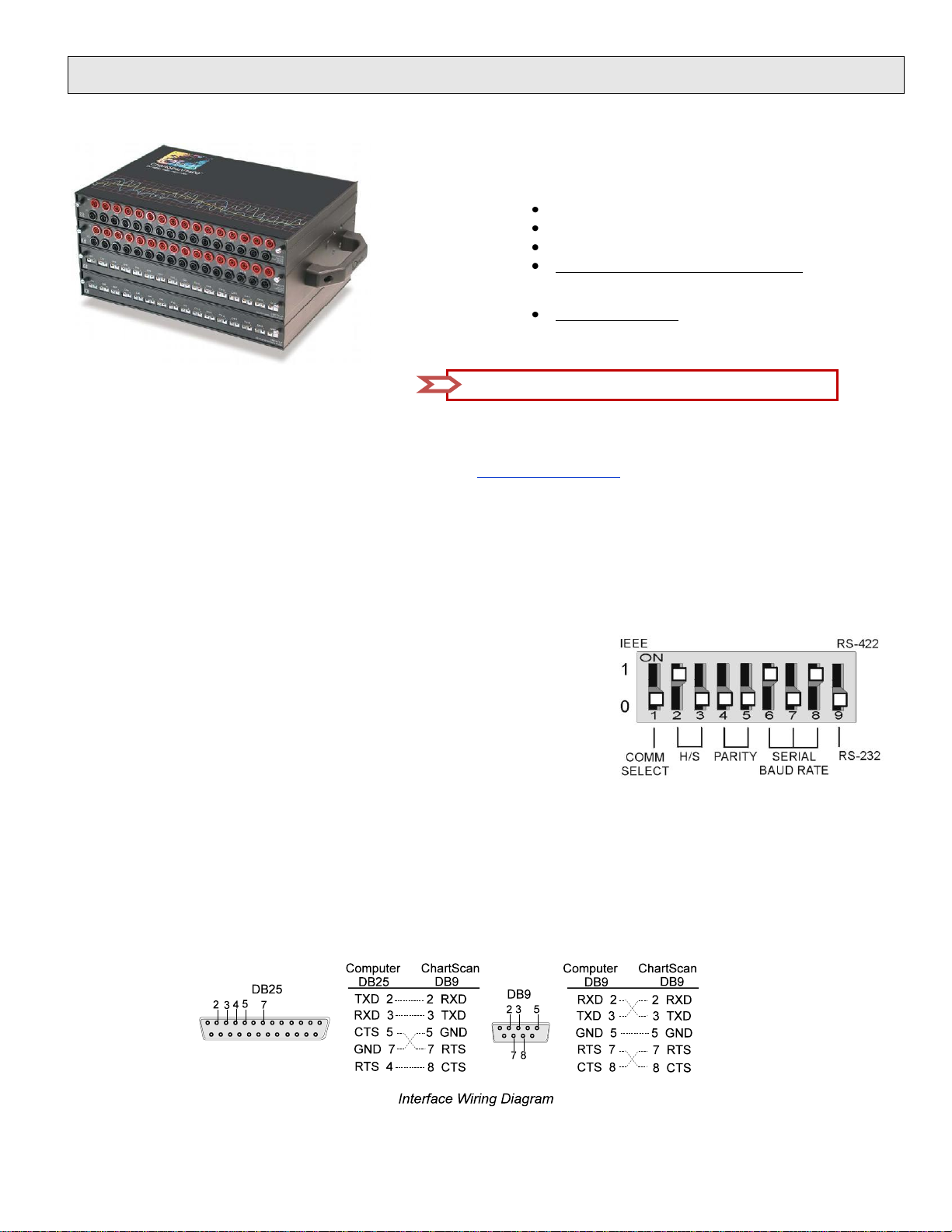
Recommended DIP Switch Configuration
Portable Data Recorder
512 MB memory; 10 GB disk space
Step 2 – Check Hardware
1. Verify that the voltage stated on the sticker [near the power switch] matches the voltage of
your intended AC power supply. If you need to change the voltage, refer to your user’s
manual.
2. Check the DIP switch, located on the rear panel. It should match the default setting as
indicated in the figure. Your user’s manual discusses setting options.
3. Signal conditioning cards are pre-installed at the factory. However,
if you need to remove or install a card, refer to your user’s manual.
Step 3 - Connect to the Host PC & Apply Power
ChartScan/1400 is pre-configured for serial port connection to the host PC. For IEEE 488 connection refer to the Hardware Installation section
of your user’s manual. For USB connection refer to the associated Quick Start document (QS RS-232_to_USB_Interface.pdf). The pdf is
included on your Data Acquisition CD (rev 8.1.2 and higher). A RS-232 to USB Interface Adapter Kit p/n CA-232-USB-KIT (available from
IOtech) is required for USB connection.
Use a CA-47 cable (or equivalent) to connect the unit to your computer. The ChartScan-end of the CA-47 cable has a DB-9 connector. The
computer end has 2 connectors (DB9 and DB25). Other crossover-type cables can be used if wired as shown in the following figure.
483-0940 rev 6.0 324601C-01
Page 2
ChartScan is typically powered from a standard AC outlet. To power the unit:
Reference Notes:
Documents are automatically installed onto your PC’s hard-drive as a part of product support at the time of software
installation. The default location is the Programs group. It can be accessed via the Windows Desktop Start Menu.
CAUTION
Do not exceed the 0.0 to 5.3 volts input levels described above. Exceeding these levels may
damage the ChartScan/1400 and void the warranty.
*324601C-01*
324601C-01
IOtech, 25971 Cannon Road, Cleveland, OH 44146-1833
Ph: (440) 439-4091 Fax: (440) 439-4093 productsupport@iotech.com Internet: www.iotech.com
483-0940 rev 6.0
1. Make sure ChartScan’s power switch is in the “0” (OFF) position.
2. Plug power cord CA-1 into ChartScan’s power connector. Plug the other end of the cord into an appropriate AC receptacle.
3. Turn ChartScan’s power switch to the “1” (ON) position. The Power LED should come on.
Note: At initial power-up, the unit performs automatic self-tests to ensure it is fully functional. Rear panel LEDs will indicate errors,
should any occur. Error messages are discussed in Chapter 1 of the user’s manual, as well as in Appendix G. The self-test takes
approximately 5 seconds to complete; after which, ChartScan/1400 is ready for normal operation.
Step 4 – Connect Input Signals
Connect channel inputs to your signal conditioning cards. Depending on the type(s) of cards used, your connections will be made via:
terminal strip, mini-plug, BNC, and/or safety jack input connectors.
ChartScan has eight digital input lines and thirty-two digital output lines available on the rear panel DB-50 connector.
Each digital output line will drive five standard TTL loads. All digital input lines are one-eighth (0.125) TTL loads. All inputs are
protected against damage from high static voltage. Normal precautions should be taken to limit the input voltages to the range of 0.0 to
5.3 volts. All digital I/O lines are referenced to digital ground.
Step 5 – Start ChartView, Configure the System, and Collect Data
1. From Windows desktop, double-click on the ChartView icon.
2. Choose the <Select Device> button.
3. Select RS-232 and click <OK>. Click <OK> again.
Note: For changes from default, refer to Chapters 4 and 7 of the ChartScan/1400 User’s Manual.
4. In the Automatic Chart Creation portion of the window, click <Create Charts> to automatically create a chart display
configuration. Note that a Channel and Alarm Setup dialog box will appear above the main window.
5. Click the <Make All Channels Active> button to enable all channels.
6. Click the <Enable SpreadSheet Reading> button. Click <OK>.
7. Push the <Start Charts and Indicators> button. Charts will begin scrolling.
 Loading...