

Page 1

CB-7012/12D/12F/12FD,
CB-7014D,
CB-7017/17F
User’s Manual
Copyright Sept., 2000 All rights are reserved.
CB-7012, CB-7014, CB-7017 User’s Manual
1
Page 2

Table of Contents
1. Introduction.....................................................5
1.1 More Information .......................................5
1.2 Pin Assignments.........................................6
1.3 Specifications.............................................9
1.4 Block Diagrams........................................12
1.5 W ire Connections.....................................14
1.6 Quick Start ...............................................16
1.7 Default Setting .........................................16
1.8 Jumper Setting .........................................16
1.9 Calibration ...............................................17
1.10 Configuration T ables..............................18
2. Commands .....................................................20
2.1 %AANNTTCCFF.....................................23
2.2 #** ...........................................................25
2.3 #AA..........................................................26
2.4 #AAN .......................................................27
2.5 $AA0........................................................28
2.6 $AA1........................................................29
2.7 $AA2........................................................30
2.8 $AA4........................................................31
2.9 $AA5VV ..................................................32
2.10 $AA6......................................................33
2
CB-7012, CB-7014, CB-7017 User’s Manual
Page 3

2.1 1 $AA8 ......................................................34
2.12 $AA8V ...................................................35
2.13 $AA9(Data)............................................36
2.14 $AAA .....................................................37
2.15 $AAF......................................................38
2.16 $AAM ....................................................39
2.17 ~AAO(Data)...........................................40
2.18 ~AAEV...................................................41
2.19 @AADI ..................................................42
2.20 @AADO(Data) ......................................43
2.21 @AAEAT ...............................................44
2.22 @AAHI(Data) ........................................45
2.23 @AALO(Data).......................................46
2.24 @AADA.................................................47
2.25 @AACA.................................................48
2.26 @AARH.................................................49
2.27 @AARL .................................................50
2.28 @AARE .................................................51
2.29 @AACE .................................................52
2.30 $AA3......................................................53
2.31 $AA5......................................................54
2.32 $AA6(SL)(SH).......................................55
2.33 $AA7(TL)(TH).......................................56
2.34 $AAA .....................................................57
CB-7012, CB-7014, CB-7017 User’s Manual
3
Page 4

2.35 $AAAV...................................................58
2.36 ~** .........................................................59
2.37 ~AA0......................................................60
2.38 ~AA1......................................................61
2.39 ~AA2......................................................62
2.40 ~AA3EVV..............................................63
2.41 ~AA4......................................................64
2.42 ~AA5PPSS.............................................65
3. Application Notes..........................................66
3.1 INIT* pin Operation.................................66
3.2 Module Status ..........................................66
3.3 Dual Watchdog Operation........................67
3.4 Digital Input and Event Counter ..............67
3.5 Digital Output ..........................................67
3.6 High/Low Alarm ......................................68
3.7 Transmitter...............................................68
3.8 Linear Mapping........................................69
HM CB COM 7012 & 17.p65
4
CB-7012, CB-7014, CB-7017 User’s Manual
Page 5

1. Introduction
CB-7000 is a family of network data acquisition and control
modules. They provide analog-to-digital, digital-to-analog, digital
input/output, timer/counter and other functions. These modules can
be controlled remotely by a set of commands. Common features of
analog input modules are as follows:
l 3000VDC isolated analog input.
l 24-bit sigma-delta ADC to provide excellent accuracy .
l Software calibration
The CB-7012 is a single channel analog input module with
high/low alarm function. The CB-7012D is the CB-7012 with a 4½
digit LED display. The CB-7012F/12FD is a CB-7012/12D with
high speed analog input function. The CB-7014D is CB-7012D
with Linear Mapping function and supports +15V loop power for a
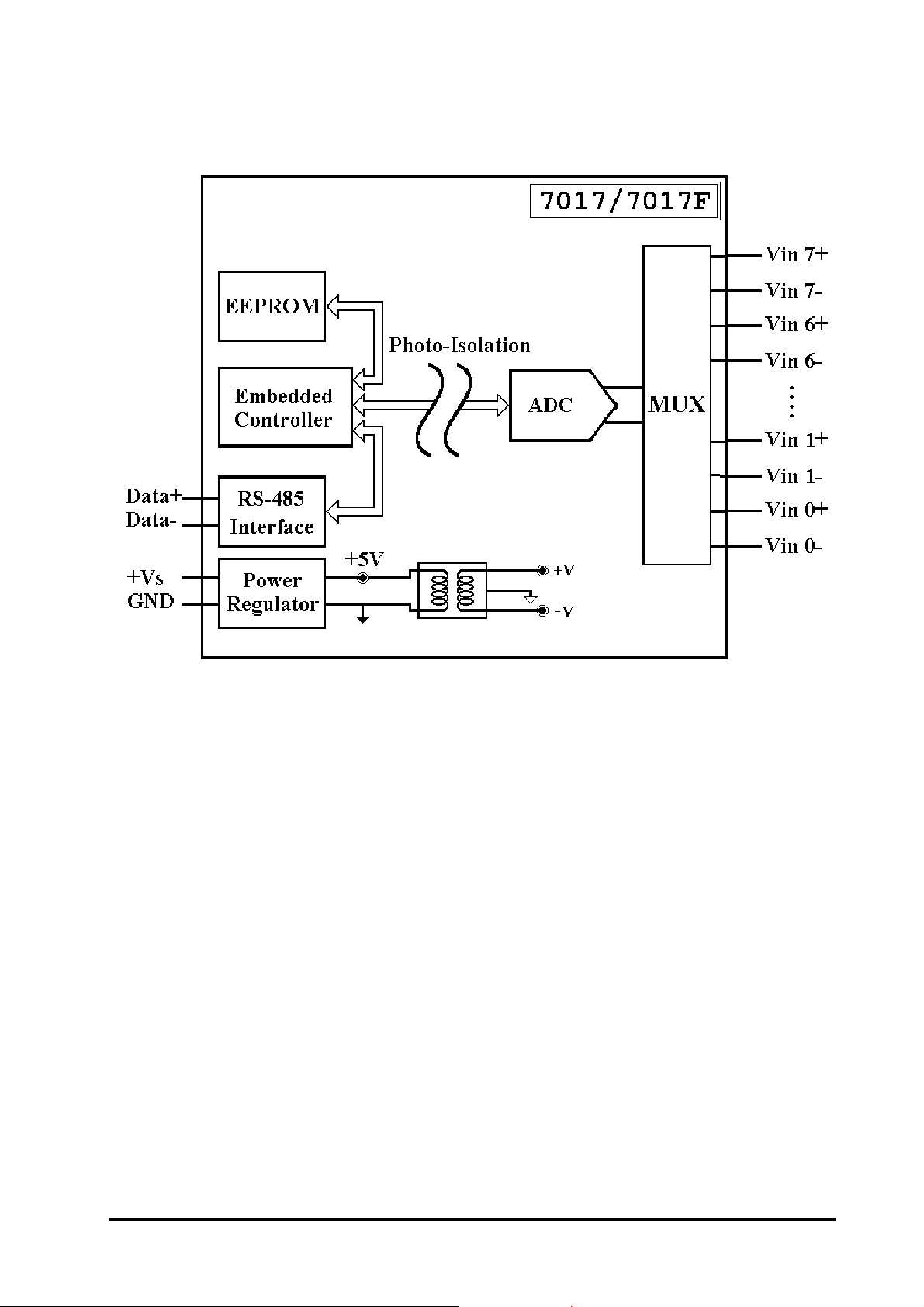
transmitter . The CB-7017 is an eight-channel analog input module.
The CB-7017F is a CB-7017 with high speed analog inputs.
1.1 More Information
Refer to “CB-7000 Bus Converter User Manual”
Chapter 1 for more information as following:
1.1 CB-7000 Overview
1.2 CB-7000 Related Documentation
1.3 CB-7000 Command Features
1.4 CB-7000 System Network Configuration
1.5 CB-7000 Dimension
CB-7012, CB-7014, CB-7017 User’s Manual
5
Page 6

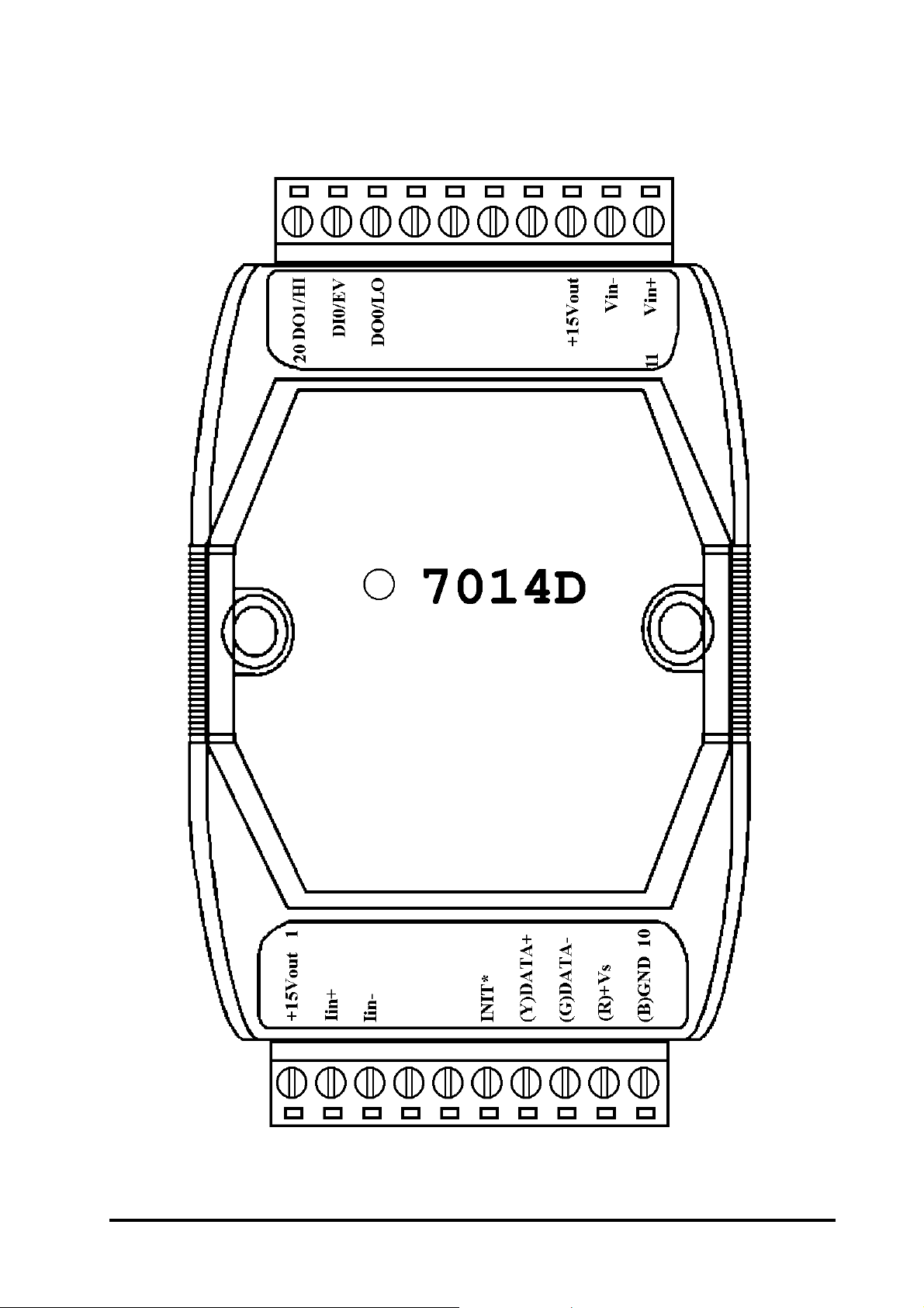
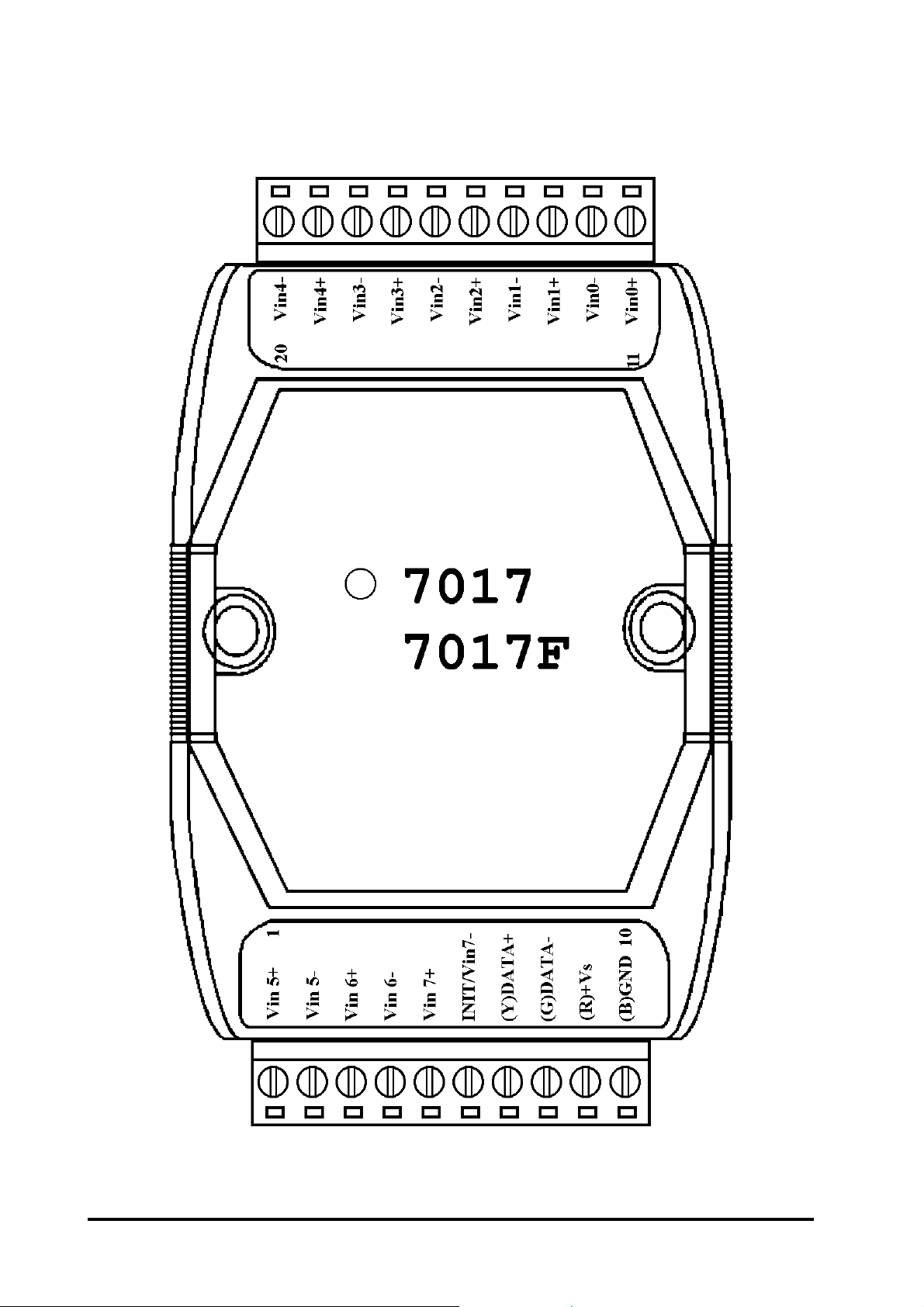
1.2 Pin Assignments
6
CB-7012, CB-7014, CB-7017 User’s Manual
Page 7
CB-7012, CB-7014, CB-7017 User’s Manual
7
Page 8
8
CB-7012, CB-7014, CB-7017 User’s Manual
Page 9

1.3 Specifications
CB-7012/CB-7012D
Analog Input
Input Channels: 1
Input T ype:
mV, V, mA (with external
125 ohms resistor)
Sampling Rate:
10 Samples/Second
Bandwidth: 5.24 Hz
Accuracy: ±0.05%
Zero Drift: 20µV/°C
Span Drift: 25ppm/°C
Event Counter
Max Input Frequency: 50 Hz
Min. Pulse W idth: 1 ms
Displayed LED
4½ digits (for CB-7012D)
Power Supply
Input: +10 to +30VDC
Consumption:
1.3W for CB-7012
1.9W for CB-7012D
CMRR: 86 dB
Input Impedance: 20 MOhms
Isolation: 3000VDC
Digital Output
Output Channels: 2
Open Collector to 30V
Output Load: sink 30 mA max
Power Dissipation: 300 mW
Digital Input
Input Channel: 1
Logic Level 0: +1V max
Logic Level 1: +3.5 to 30V
CB-7012, CB-7014, CB-7017 User’s Manual
9
Page 10

CB-7012F/CB-7012FD
CB-7014D
Analog Input
Input Channel:1
Input T ype:
mV, V, mA (with external
125 ohms resistor)
Fast Mode Sampling Rate:
100 Samples/Second
Fast Mode Bandwidth: 52.4 Hz
Fast Mode Accuracy: ±0.25%
Normal Mode:
Same as CB-7012
Analog Input
Input Channel and Type:
1 Voltage Input: mV, V
1 Current Input: mA
Sampling Rate:
10 Samples/Second
Bandwidth: 5.24 Hz
Accuracy: ±0.05%
Zero Drift: 20µV/°C
Span Drift: 25ppm/°C
CMRR@50/60Hz: 150 dB min
Input Impedance: 20 MOhms
Isolation: 3000VDC
Digital Input/Output
Same as CB-7012
Displayed LED
4½ digits (for CB-7012FD)
Power Supply
Input: +10 to +30VDC
Consumption:
1.3 W for CB-7012F
1.9 W for CB-7012FD
Input Impedance:
Voltage Input: 30 KOhms
Current Input: 125 Ohms
Isolation: 3000VDC
Excitation Voltage Output
Output Rating: 30 mA@15V
Digital Input/Output
Same as CB-7012
Displayed LED
4½ digits
Power Supply
10
Input: +10 to +30VDC
Consumption: 1.9 W
CB-7012, CB-7014, CB-7017 User’s Manual
Page 11

CB-7017
CB-7017F
Analog Input
Input Channel:
8 differential or 6 differential and 2 single-ended by
jumper selection.
Analog Input T ype:
mV, V, mA (with external
125 ohms resistor)
Sampling Rate:
10 Samples/Second
Bandwidth: 15.7 Hz
Analog Input
Input Channel:
8 differential or 6 differential and 2 single-ended by
jumper selection.
Analog Input T ype:
mV, V, mA (with external
125 ohms resistor)
Fast Mode Sampling Rate:
75 Samples/Second
Fast Mode Bandwidth: 78.7 Hz
Accuracy: ±0.1%
Zero Drift: 20µV/°C
Span Drift: 25ppm/°C
CMRR: 86dB
Input Impedance: 20 MOhms
Overvoltage Protection: ±35V
Isolation: 3000VDC
Power Supply
Input: +10 to +30VDC
Consumption: 1.3 W
Fast Mode Accuracy: ±0.5%
Normal Mode:
Same as CB-7017
Input Impedance: 20M Ohms
Overvoltage Protection: ±35V
Isolation: 3000VDC
Power Supply
Input: +10 to +30VDC
Consumption: 1.3 W
CB-7012, CB-7014, CB-7017 User’s Manual
11
Page 12
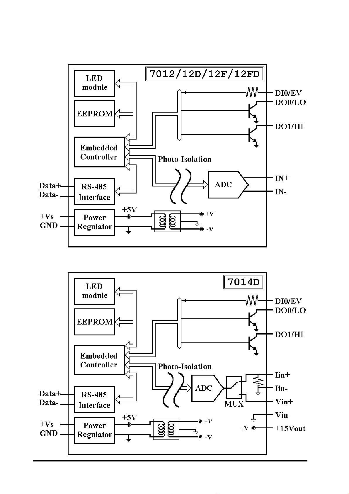
1.4 Functional Block Diagrams
12
CB-7012, CB-7014, CB-7017 User’s Manual
Page 13
CB-7012, CB-7014, CB-7017 User’s Manual
13
Page 14
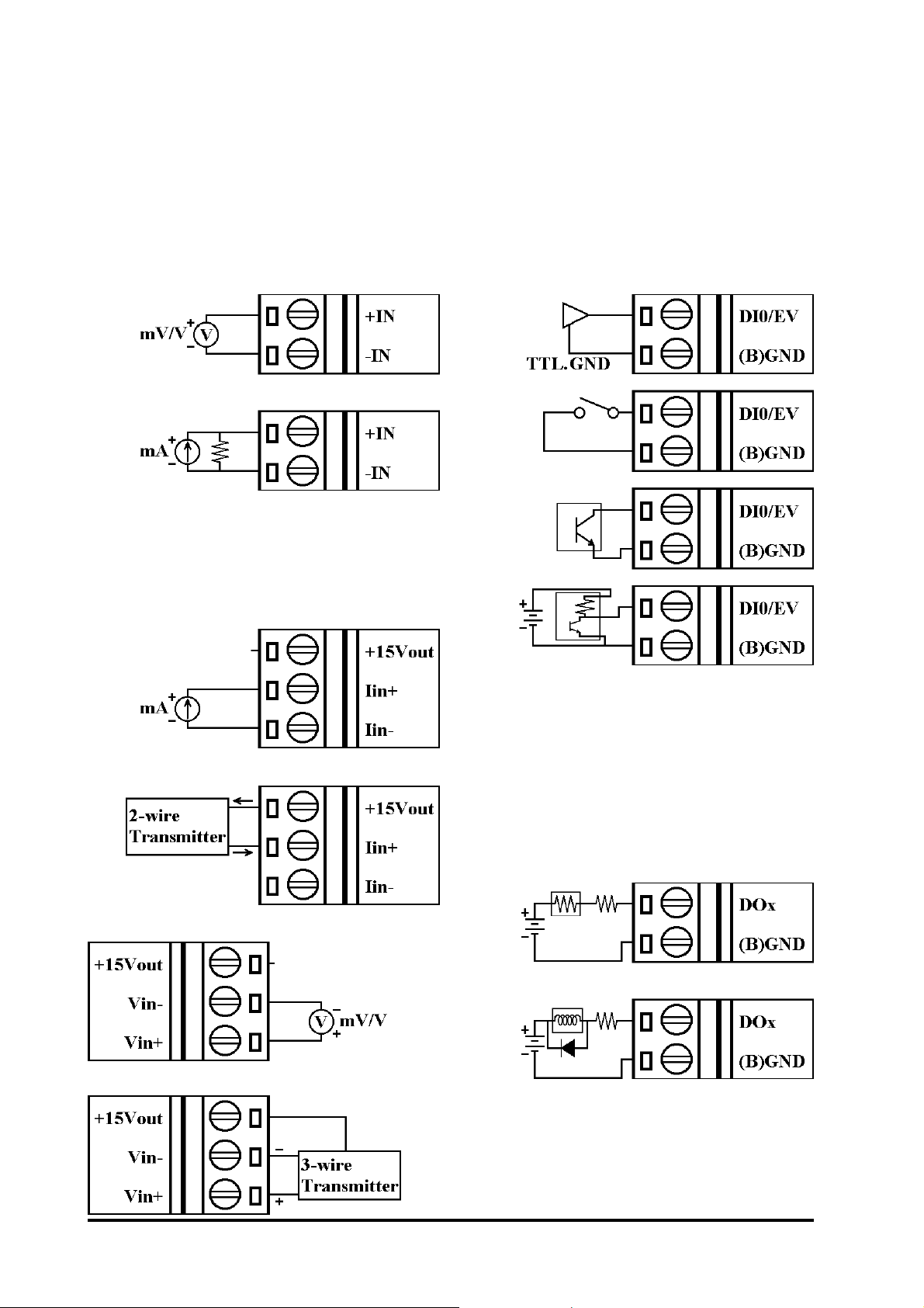
1.5 Connections
CB-7012/12D/12F/12FD
Analog Input W ire Connection
CB-7014D Analog Input Wire
Connection
CB-7012/12D/12F/12FD/14D
Digital Input W ire Connection
CB-7012/12D/12F/12FD/14D
Digital Output Wire Connection
14
CB-7012, CB-7014, CB-7017 User’s Manual
Page 15
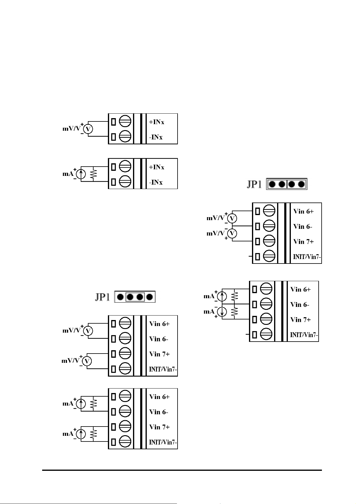
CB-7017/17F Analog Input
CB-7017/17F Analog Input
Channel 0 to 5 Wire Connection
CB-7017/17F Analog Input
Channel 6 and 7 Wire Connection, when the jumper JP1 set-
Channel 6 and 7 Wire Connection, when the jumper JP1 setting is INIT* mode. (Remove
cover to gain access to jumper
JP1.)
ting is 8 differential mode.
CB-7012, CB-7014, CB-7017 User’s Manual
15
Page 16
1.6 Quick Start
Refer to “CB-7000 Bus Converter User Manual” and
“Getting Started” for more details.
1.7 Default Setting
Default setting for CB-7012/12D/12F/12FD/14D/17/17F:
l Address: 01
l Analog Input Type: Type 08, −10 to +10 V
l Baud rate: 9600 bps
l 60 Hz filter rejection, Checksum disable, eng. unit format
l CB-7017/17F set as 6 differential and 2 single-ended modes
l CB-7012F and CB-7017F set as Fast Mode
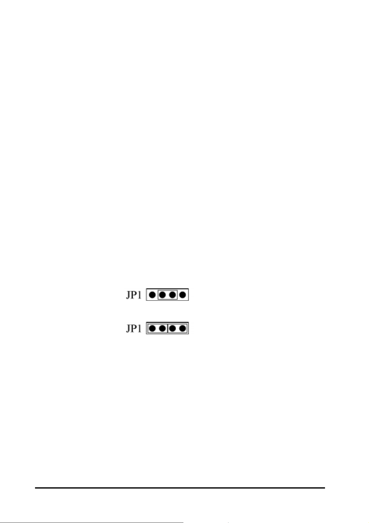
1.8 Jumper Setting
CB-7017/17F: Jumper JP1 for select the pin INIT*/Vin 7Select 8 differential mode, the pin I INIT*/Vin7- is set to V in7-
Select INIT* mode, the pint INIT*/Vin7- is set to INIT*
16
CB-7012, CB-7014, CB-7017 User’s Manual
Page 17

1.9 Calibration
Don’t Perform Calibration Until You Understand Procedure.
Calibration requirements for CB-7012/12D/12F/12FD/14D/17/17F:
When calibrating type 0D for CB-7012/12D/12F/12FD/17/17F,
connect external shunt resistor , 125 ohms, 0.1% (Ref. Sec. 1.5).
edoCepyT8090A0B0C0D0
tupnIoreZV0V0V0Vm0Vm0Am0
tupnInapSV01+V5+V1+Vm005+Vm051+Am02+
Calibration Sequence:
1. Connect calibration voltage/current to module’s input. For
CB-7017/17F, connect to channel 0.
(To connect, see Sec. 1.5)
2. Warm-Up for 30 minutes.
3. Set Type to 08. -> See Sec. 2.1.
4. Enable Calibration. -> See Sec. 2.18.
5. Apply Zero Calibration Voltage.
6. Perform Zero Calibration Command. See Sec. 2.6.
7. Apply “Span Input” Calibration Voltage.
8. Perform Span Calibration Command. See Sec. 2.5.
9. Repeat step 4 to step 8 three times.
CB-7012, CB-7014, CB-7017 User’s Manual
17
Page 18

1.10 Configuration Tables
Configuration T able for CB-7012/12F/12D/12FD/14D/17/17F:
Baud rate Setting (CC)
edoC30405060708090A0
etarduaB0021004200840069002910048300675002511
Analog Input Type Setting (TT)
edoCepyT8090A0B0C0D0
tupnI.niMV01-V5-V1-Vm005-Vm051-Am02tupnIxaMV01+V5+V1+Vm005+Vm051+Am02+
Data Format Setting (FF)
76543210
1*2*3* 000 4*
*1: 0 = 60 Hz rejection
1 = 50 Hz rejection
*2: Checksum Bit: 0 = Disable, 1 = Enable
*3: Fast/Normal Bit: 0 = Normal, 1 = Fast
(For CB-7012F/12FD/17F only)
*4: 00 = Engineering Unit Format
01 = Percent Format
18
10 = 2’s Complement HEX Format
CB-7012, CB-7014, CB-7017 User’s Manual
Page 19

Analog input type and data format table
epyT
edoC
80V01+ot01-
90V5+ot5-
A0V1+ot1-
egnaRtupnItamroFataD.S.F+oreZ.S.F-
tinUreenignE000.01+000.00+000.01-
RSFfo%00.001+00.000+00.001-
XEHtnemelpmocs'2FFF700000008
tinUreenignE0000.5+0000.0+0000.5-
RSFfo%00.001+00.000+00.001-
XEHtnemelpmocs'2FFF700000008
tinUreenignE0000.1+0000.0+0000.1-
RSFfo%00.001+00.000+00.001-
XEHtnemelpmocs'2FFF700000008
tinUreenignE00.005+00.000+00.005-
B0
Vm
C0
Vm
D0
Am
005+ot005-
RSFfo%00.001+00.000+00.001-
XEHtnemelpmocs'2FFF700000008
tinUreenignE00.051+00.000+00.051-
051+ot051-
RSFfo%00.001+00.000+00.001-
XEHtnemelpmocs'2FFF700000008
tinUreenignE000.02+000.00+000.02-
02+ot02-
RSFfo%00.001+00.000+00.001-
XEHtnemelpmocs'2FFF700000008
CB-7012, CB-7014, CB-7017 User’s Manual
19
Page 20

2. Commands
Command Format: (Delimiter)(Address)(Command)[CHK](cr)
Response Format: (Delimiter)(Address)(Data)[CHK](cr)
[CHK] 2-character checksum
(cr) end-of-command character , character return (0x0D)
steSdnammoClareneG
dnammoCesnopseRnoitpircseDnoitceS
FFCCTTNNAA%AA!noitarugifnoCeludoMteS 1.2.ceS
**#esnopseRoNgnilpmaSdezinorhcnyS 2.2.ceS
AA#)ataD(>tupnIgolanAdaeR 3.2.ceS
NAA#)ataD(>
morftupnIgolanAdaeR
Nlennahc
0AA$AA!noitarbilaCnapSmrofreP 5.2.ceS
1AA$AA!noitarbilaCoreZmrofreP 6.2.ceS
2AA$FFCCTTNNAA!noitarugifnoCdaeR 7.2.ceS
4AA$)ataD(SAA>ataDdezinorhcnySdaeR 8.2.ceS
VV5AA$AA!elbanElennahCteS 9.2.ceS
6AA$VVAA!sutatSlennahCdaeR 01.2.ceS
8AA$VAA!noitarugifnoCDELdaeR 11.2.ceS
V8AA$AA!noitarugifnoCDELteS 21.2.ceS
)ataD(9AA$AA!ataDDELteS 31.2.ceS
4.2.ceS
20
AAA$)ataD(!atadlennahc8daeR 41.2.ceS
FAA$)ataD(AA!noisreVerawmriFdaeR 51.2.ceS
MAA$)ataD(AA!emaNeludoMdaeR 61.2.ceS
)ataD(OAA~AA!emaNeludoMteS 71.2.ceS
VEAA~AA!noitarbilaCelbasiD/elbanE 81.2.ceS
CB-7012, CB-7014, CB-7017 User’s Manual
Page 21

dnammoCesnopseRnoitpircseDnoitceS
steSdnammoCretnuoCtnevEdnamralA,tuptuO/tupnIlatigiD
IDAA@IIOOSAA!
dnaO/IlatigiDdaeR
sutatSmralA
)ataD(ODAA@AA!tuptuOlatigiDteS 02.2.ceS
TAEAA@AA!mralAelbanE 12.2.ceS
)ataD(IHAA@AA!mralAhgiHteS 22.2.ceS
)ataD(OLAA@AA!mralAwoLteS 32.2.ceS
ADAA@AA!mralAelbasiD 42.2.ceS
ACAA@AA!mralAhctaLraelC 52.2.ceS
HRAA@)ataD(AA!mralAhgiHdaeR 62.2.ceS
LRAA@)ataD(AA!mralAwoLdaeR 72.2.ceS
ERAA@)ataD(AA!retnuoCtnevEdaeR 82.2.ceS
91.2.ceS
ECAA@AA!retnuoCtnevEraelC 92.2.ceS
steSdnammoCgnippaMraeniL
dnammoCesnopseRnoitpircseDnoitceS
hgiH/woLecruoSdaeR
3AA$)HS()LS(AA!
hgiH/woLtegraTdaeR
5AA$)HT()LT(AA!
hgiH/woLecruoSteS
)HS()LS(6AA$AA!
hgiH/woLtegraTteS
)HT()LT(7AA$AA!
gnippaMraeniLdaeR
AAA$VAA!
sutatS
gnippaMraeniLrofseulaV
03.2.ceS
13.2.ceS
gnippaMraeniLrofseulaV
23.2.ceS
gnippaMraeniLrofseulaV
33.2.ceS
gnippaMraeniLrofseulaV
43.2.ceS
VAAA$AA!
gnippaM
CB-7012, CB-7014, CB-7017 User’s Manual
raeniLelbasiD/elbanE
53.2.ceS
21
Page 22

steSdnammoCdetaleRgodhctaWtsoH
dnammoCesnopseRnoitpircseD noitceS
**~esnopseRoNKOtsoH 63.2.ceS
0AA~SSAA!sutatSeludoMdaeR 73.2.ceS
1AA~AA!sutatSeludoMteseR 83.2.ceS
2AA~VVAA!
VVE3AA~AA!
4AA~SSPPAA!
SSPP5AA~AA!
godhctaWtsoHdaeR
93.2.ceS
lavretnItuoemiT
godhctaWtsoHteS
04.2.ceS
lavretnItuoemiT
dnaeulaVnOrewoPdaeR
14.2.ceS
eulaVefaS
dnaeulaVnOrewoPteS
24.2.ceS
eulaVefaS
22
CB-7012, CB-7014, CB-7017 User’s Manual
Page 23

2.1 %AANNTTCCFF
Description: Set Module Configuration
Syntax: %AANNTTCCFF[CHK](cr)
% a Delimiter character
A A Address of module to set (00 to FF)
NN new Address for module to set (00 to FF)
TT new type for module to set (Ref. Sec. 1.10)
CC new baudrate for receiving module (Ref. Sec. 1.10). Short
INIT* to ground when changing baudrate. (Ref. Sec. 3.1)
FF New data format for module (Ref. Sec. 1.10).
Short INIT* to ground when changing checksum setting.
(Ref. Sec. 3.1)
Response: Valid Command: !AA[CHK](cr)
Invalid Command: ?AA[CHK](cr)
Syntax or communication error may get no response.
! Delimiter for valid command
? Delimiter for invalid command. If you change baud
rate or checksum setting without shorting INIT* to ground,
the module will return an invalid command.
A A Address of responding module (00 to FF)
Example:
Command: %0102080600 Receive: !02
Change Address from 01 to 02, return successful.
Command: %0202080602 Receive: !02
Change data format from 00 to 02, return successful.
CB-7012, CB-7014, CB-7017 User’s Manual
23
Page 24

Related Command:
Sec. 2.7 $AA2
Related Topics:
Sec. 1.10, Configuration Tables; Sec. 3.1, INIT* pin Operation
24
CB-7012, CB-7014, CB-7017 User’s Manual
Page 25

2.2 #**
Description: Synchronized Sampling
Note: This command is for CB-7012/12D/12F/12FD/14D only.
Syntax: #**[CHK](cr)
# a Delimiter character
** synchronized sampling command
Response: No response
Example:
Command: #** No response
Send synchronized sampling command.
Command: $014 Receive: >011+025.123
First read, get status = 1.
Command: $014 Receive: >010+025.123
Second read, get status = 0.
Related Command:
Sec. 2.8 $AA4
CB-7012, CB-7014, CB-7017 User’s Manual
25
Page 26

2.3 #AA
Description: Read Analog Input
Syntax: #AA[CHK](cr)
# Delimiter character
A A Address of module (00 to FF)
Response: Valid Command: >(Data)[CHK](cr)
Syntax or communication error may get no response.
> Delimiter for valid command
(Data) Analog input value, reference Sec. 1.10 for its format
When using #AA command to CB-7017/17F , the data is
the combination for each channel respectively .
Example:
Command: #01 Receive: >+02.635
Read Address 01, get data successful.
Command: #02 Receive: >4C53
Read Address 02, get data in HEX format successfully .
Command: #04
Receive: >+05.123+04.153+07.234-02.356+10.000-
05.133+02.345+08.234
The module Address 04 is CB-7017. Read Address 04 to
get data from all eight channels.
Related Command:
Sec. 2.1, %AANNTTCCFF; Sec. 2.7, $AA2
Related Topics:
Sec. 1.10, Configuration T ables
26
CB-7012, CB-7014, CB-7017 User’s Manual
Page 27

2.4 #AAN
Description: Read Analog Input from channel N
Note: This command is for CB-7017/17F only.
Syntax: #AAN[CHK](cr)
# Delimiter character
A A Address for module (00 to FF)
N channel to read, from 0 to 7
Response: Valid Command: >(Data)[CHK](cr)
Invalid Command: ?AA[CHK](cr)
Syntax or communication error may get no response.
> Delimiter for valid command
? Delimiter for invalid command
A A Address of responding module (00 to FF)
(Data) analog input value; see Sec. 1.10 for its format
Example:
Command: #032 Receive: >+02.513
Read Address 03 channel 2, get data successfully .
Command: #029 Receive: ?02
Read Address 02 channel 9, return error channel number .
Related Command:
Sec. 2.1 %AANNTTCCFF, Sec. 2.7 $AA2
Related Topics:
Sec. 1.10 Configuration T ables
CB-7012, CB-7014, CB-7017 User’s Manual
27
Page 28

2.5 $AA0
Description: Perform Span Calibration
Syntax: $AA0[CHK](cr)
$ Delimiter character
A A Address of module to set (00 to FF)
0 Command for performing span calibration
Response: Valid Command: !AA[CHK](cr)
Invalid Command: ?AA[CHK](cr)
Syntax or communication error may get no response.
! Delimiter for valid command
? Delimiter for invalid command
A A Address of responding module (00 to FF)
Example:
Command: $010 Receive: !01
Perform Address 01 span calibration, return successful.
Command: $020 Receive: ?02
Perform Address 02 span calibration; return calibration not
enabled before performing calibration command.
Related Command:
Sec. 2.6 $AA1, Sec. 2.18 ~AAEV
Related Topics:
Sec. 1.9 Calibration
28
CB-7012, CB-7014, CB-7017 User’s Manual
Page 29

2.6 $AA1
Description: Perform Zero Calibration
Syntax: $AA1[CHK](cr)
$ Delimiter character
A A Address of module to set (00 to FF)
1 Command for performing zero calibration
Response: Valid Command: !AA[CHK](cr)
Invalid Command: ?AA[CHK](cr)
Syntax or communication error may get no response.
! Delimiter for valid command
? Delimiter for invalid command
A A Address of responding module (00 to FF)
Example:
Command: $011 Receive: !01
Perform Address 01 zero calibration, return successful.
Command: $021 Receive: ?02
Perform Address 02 zero calibration; returns calibration not
enabled before performing calibration command.
Related Command:
Sec. 2.5, $AA0; Sec. 2.18 ~AAEV
Related Topics:
Sec. 1.9 Calibration
CB-7012, CB-7014, CB-7017 User’s Manual
29
Page 30

2.7 $AA2
Description: Read Configuration
Syntax: $AA2[CHK](cr)
$ Delimiter character
A A Address of module (00 to FF)
2 Command for reading configuration
Response: Valid Command:
!AA TTCCFF[CHK](cr)
Invalid Command: ?AA[CHK](cr)
Syntax or communication error may get no response.
! Delimiter for valid command
? Delimiter for invalid command
A A Address of responding module (00 to FF)
TT Type code of module (reference Sec. 1.10)
CC Baud rate code of module (reference Sec. 1.10)
FF Data format of module (reference Sec. 1.10)
Example:
Command: $012 Receive: !01080600
Read Address 01 configuration, return successful.
Command: $022 Receive: !020A0602
Read Address 02 configuration, return successful.
Related Command:
Sec. 2.1 %AANNTTCCFF
Related Topics:
Sec. 1.10, Configuration Tables; Sec. 3.1, INIT* pin Operation
30
CB-7012, CB-7014, CB-7017 User’s Manual
Page 31

2.8 $AA4
Description: Read Synchronized Data
Syntax: $AA4[CHK](cr)
$ Delimiter character
A A Address of module (00 to FF)
4 Command for reading synchronized data
Response: Valid Command: >AAS(Data)[CHK](cr)
Invalid Command: ?AA[CHK](cr)
Syntax or communication error may get no response.
! Delimiter for valid command
? Delimiter for invalid command
A A Address of responding module (00 to FF)
S Status of synchronized data, 1 = first read, 0 = been read
(Data) Synchronized data, format reference Sec. 1.10
Example:
Command: $014 Receive: ?01
Read Address 01 synchronized data, return no valid data.
Command: #** Receive: no response
Preform synchronized sampling
Command: $014 Receive: >011+02.556
Read Address 01 synchronized data, return status 1 and data.
Command: $014 Receive: >010+02.556
Read Address 01 synchronized data, return status 0 and data.
Related Command:
Sec. 2.2, #**
Note: This command is for CB-7012/12D/12F/12FD/14D only.
CB-7012, CB-7014, CB-7017 User’s Manual
31
Page 32

2.9 $AA5VV
Description: Set Channel Enable
Note: This command is for CB-7017/17F only.
Syntax: $AA5VV[CHK](cr)
$ Delimiter character
A A Address of module to set (00 to FF)
5 Command to set channel enable
VV channel enable/disable, 00 is all disabled and FF is all
enabled.
Response: Valid Command: !AA[CHK](cr)
Invalid Command: ?AA[CHK](cr)
Syntax or communication error may get no response.
! Delimiter for valid command
? Delimiter for invalid command
A A Address of responding module (00 to FF)
Example:
Command: $0155A Receive: !01
Set Address 01 to enable channel 1,3,4,6 and disable channel
0,2,5,7. Return successful.
Command: $016 Receive: !015A
Read Address 01 channel status. Return channel 1,3,4,6 are
enabled and channel 0,2,5,7 are disabled.
Related Command:
Sec. 2.10 $AA6
32
CB-7012, CB-7014, CB-7017 User’s Manual
Page 33

2.10 $AA6
Description: Read Channel Status
Note: The command is for CB-7017/17F only.
Syntax: $AA6[CHK](cr)
$ Delimiter character
A A Address of module (00 to FF)
6 Command for read channel status
Response: Valid Command: !AAVV[CHK](cr)
Invalid Command: ?AA[CHK](cr)
Syntax or communication error may get no response.
! Delimiter for valid command
? Delimiter for invalid command
A A Address of responding module (00 to FF)
VV channel enable/disable; 00 is all-disabled and FF is all-
enabled.
Example:
Command: $015A5 Receive: !01
Set Address 01 to enable channel 0,2,5,7 and disable channel
1,3,4,6. Return successful.
Command: $016 Receive: !01A5
Read Address 01 channel status. Return channel 0,2,5,7 are
enabled and channel 1,3,4,6 are disabled.
Related Command:
Sec. 2.9 $AA5VV
CB-7012, CB-7014, CB-7017 User’s Manual
33
Page 34

2.11 $AA8
Description: Read LED Configuration
Note: The command is for CB-7012D/12FD/14D only.
Syntax: $AA8[CHK](cr)
$ Delimiter character
A A Address of module (00 to FF)
8 Command for reading LED configuration
Response: Valid Command: !AAV[CHK](cr)
Invalid Command: ?AA[CHK](cr)
Syntax or communication error may get no response.
! Delimiter for valid command
? Delimiter for invalid command
A A Address of responding module (00 to FF)
V LED configuration
1 = module control, 2 = host control
Example:
Command: $018 Receive: !011
Read Address 01 LED configuration, return module control.
Command: $028 Receive: !012
Read Address 02 LED configuration, return host control.
Related Command:
Sec. 2.12, $AA8V; Sec. 2.13, $AA9(Data)
34
CB-7012, CB-7014, CB-7017 User’s Manual
Page 35

2.12 $AA8V
Description: Set LED Configuration
Note: The command is for CB-7012D/12FD/14D only.
Syntax: $AA8V[CHK](cr)
$ Delimiter character
A A Address of module to set (00 to FF)
8 Command for setting LED configuration
V 1=Set LED to module, 2=Set LED to host
Response: Valid Command: !AA[CHK](cr)
Invalid Command: ?AA[CHK](cr)
Syntax or communication error may get no response.
! Delimiter for valid command
? Delimiter for invalid command
A A Address of responding module (00 to FF)
Example:
Command: $0182 Receive: !01
Set Address 01 LED to host control, return successful.
Command: $0281 Receive: !02
Set Address 02 LED to module control, return successful.
Related Command:
Sec. 2.11, $AA8; Sec. 2.13, $AA9(Data)
CB-7012, CB-7014, CB-7017 User’s Manual
35
Page 36

2.13 $AA9(Data)
Description: Set LED Data
Note: This command is for CB-7012D/12FD/14D only.
Syntax: $AA9(Data)[CHK](cr)
$ Delimiter character
A A Address of module to set (00 to FF)
9 Command for setting LED data
(Data) Data for show on the LED, from -19999. to +19999.
The data format is a sign, 5 numerals and a decimal point.
Response: Valid Command: !AA[CHK](cr)
Invalid Command: ?AA[CHK](cr)
Syntax or communication error may get no response.
! Delimiter for valid command
? Delimiter for invalid command or LED not set to host
control.
A A Address of responding module (00 to FF)
Example:
Command: $019+123.45 Receive: !01
Send Address 01 LED data +123.45, return successful.
Command: $029+512.34 Receive: ?02
Send Address 02 LED data +512.34; returns that the LED is
not set in the host mode.
Related Command:
Sec. 2.11 $AA8, Sec. 2.12 $AA8V
36
CB-7012, CB-7014, CB-7017 User’s Manual
Page 37

2.14 $AAA
Description: Read eight channel of data
Note: The command is for CB-7017/17F only.
Syntax: $AAA[CHK](cr)
$ Delimiter character
A A Address of module (00 to FF)
A Command for reading eight channels of analog input data
Response: Valid Command:
>(Data1)..(Data8)[CHK](cr)
Invalid Command: ?AA[CHK](cr)
Syntax or communication error may get no response.
! Delimiter for valid command
? Delimiter for invalid command
A A Address of responding module (00 to FF)
(Data1)...(Data8) 8 channel analog input data, in 2’s complement
HEX format.
Example:
Command: $01A
Receive: >0000012301257FFF1802744F98238124
Read Address 01 8-channel analog input data, return
successful.
Related Command:
Sec. 2.3, #AA
CB-7012, CB-7014, CB-7017 User’s Manual
37
Page 38

2.15 $AAF
Description: Read Firmware Version
Syntax: $AAF[CHK](cr)
$ Delimiter character
A A Address of module (00 to FF)
F Command for read firmware version
Response: Valid Command: !AA(Data)[CHK](cr)
Invalid Command: ?AA[CHK](cr)
Syntax or communication error may get no response.
! Delimiter for valid command
? Delimiter for invalid command
A A Address of responding module (00 to FF)
(Data) firmware version of module
Example:
Command: $01F Receive: !01A2.0
Read Address 01 firmware version, return version A2.0.
Command: $02F Receive: !01B1.1
Read Address 02 firmware version, return version B1.1.
38
CB-7012, CB-7014, CB-7017 User’s Manual
Page 39

2.16 $AAM
Description: Read Module Name
Syntax: $AAM[CHK](cr)
$ Delimiter character
A A Address of module (00 to FF)
M Command for read module name
Response: Valid Command: !AA(Data)[CHK](cr)
Invalid Command: ?AA[CHK](cr)
Syntax or communication error may get no response.
! Delimiter for valid command
? Delimiter for invalid command
A A Address of responding module (00 to FF)
(Data) Name of module
Example:
Command: $01M Receive: !017012
Read Address 01 module name, return name 7012.
Command: $03M Receive: !037014D
Read Address 03 module name, return name 7014D.
Related Command:
Sec. 2.17, ~AAO(Data)
CB-7012, CB-7014, CB-7017 User’s Manual
39
Page 40

2.17 ~AAO(Data)
Description: Module to set Name
Syntax: ~AAO(Data)[CHK](cr)
~ Delimiter character
A A Address of module to set (00 to FF)
O Command to set module name
(Data) new name for module, max 6 characters
Response: Valid Command: !AA[CHK](cr)
Invalid Command: ?AA[CHK](cr)
Syntax or communication error may get no response.
! Delimiter for valid command
? Delimiter for invalid command
A A Address of responding module (00 to FF)
Example:
Command: ~01O7012 Receive: !01
Set Address 01 module name to 7012, return successful.
Command: $01M Receive: !017012
Read Address 01 module name, return 7012.
Related Command:
Sec. 2.16, $AAM
40
CB-7012, CB-7014, CB-7017 User’s Manual
Page 41

2.18 ~AAEV
Description: Enable/Disable Calibration
Syntax: ~AAEV[CHK](cr)
~ Delimiter character
A A Address of module to set (00 to FF)
E Command to enable/disable calibration
V 1=Enable/0=Disable calibration
Response: Valid Command: !AA[CHK](cr)
Invalid Command: ?AA[CHK](cr)
Syntax or communication error may get no response.
! Delimiter for valid command
? Delimiter for invalid command
A A Address of responding module (00 to FF)
Example:
Command: $010 Receive: ?01
Perform Address 01 span calibration, returns the command is
invalid before enabling calibration.
Command: ~01E1 Receive: !01
Set Address 01 to enable calibration, return successful.
Command: $010 Receive: !01
Preform Address 01 span calibration, return successful.
Related Command:
Sec. 2.5, $AA0, Sec. 2.6, $AA1
Related Topic:
Sec. 1.9, Calibration
CB-7012, CB-7014, CB-7017 User’s Manual
41
Page 42

2.19 @AADI
Description: Read Digital I/O and Alarm Status
Note: This command is for CB-7012/12D/12F/12FD/14D only.
Syntax: @AADI[CHK](cr)
@ Delimiter character
A A Address of module (00 to FF)
DI Command for reading digital input and alarm status
Response: Valid Command: !AASOOII[CHK](cr)
Invalid Command: ?AA[CHK](cr)
Syntax or communication error may get no response.
! Delimiter for valid command
? Delimiter for invalid command
A A Address of responding module (00 to FF)
S alarm enable status, 0=alarm disable, 1=momentary alarm
enabled, 2=latch alarm enabled.
OO digital output status; 00=DO0 off, DO1 off, 01=DO0
on, DO1 off, 02=DO0 off, DO1 on, 03=OD0 on, DO1 on.
I I digital input status, 00=input low , 01=input high level.
Example:
Command: @01DI Receive: !0100001
Read Address 01 digital input, return alarm disable, digital
output all off, and digital input high level.
Related Command:
Sec. 2.20, @AADO(Data); Set. 2.21, @AAEAT; Sec. 2.24,
@AADA
Related Topic:
Sec. 3.4, Digital Input and Event Counter; Sec. 3.5, Digital Output
42
CB-7012, CB-7014, CB-7017 User’s Manual
Page 43

2.20 @AADO(Data)
Description: Set Digital Output
Note: This command is for CB-7012/12D/12F/12FD/14D only.
Syntax: @AADO(Data)[CHK](cr)
@ Delimiter character
A A Address of module to set (00 to FF)
DO Command for set digital output
(Data) output value, 00=DO0 off, DO1 off, 01=DO0 on, DO1
off, 02=DO0 off, DO1 on, 03=DO0 on, DO1 on
Response: Valid Command: !AA[CHK](cr)
Invalid Command: ?AA[CHK](cr)
Syntax or communication error may get no response.
! Delimiter for valid command
? Delimiter for invalid command. When the alarm is
enabled, the command will return invalid.
A A Address of responding module (00 to FF)
Example:
Command: @01DO00 Receive: !01
Set Address 01 digital output 00, return successful.
Related Command:
Sec. 2.19, @AADI; Sec. 2.21, @AAEAT; Sec. 2.24, @AADA
Related Topic:
Sec. 3.5, Digital Output
CB-7012, CB-7014, CB-7017 User’s Manual
43
Page 44

2.21 @AAEAT
Description: Enable Alarm
Note: This command is for CB-7012/12D/12F/12FD/14D only.
Syntax: @AAEA T[CHK](cr)
@ Delimiter character
A A Address of receiving module (00 to FF)
EA Command to enable alarm.
T Alarm type, M=momentary alarm, L=latch alarm.
Response: Valid Command: !AA[CHK](cr)
Invalid Command: ?AA[CHK](cr)
Syntax or communication error may get no response.
! Delimiter for valid command
? Delimiter for invalid command
A A Address of responding module (00 to FF)
Example:
Command: @01EAM Receive: !01
Set Address 01 momentary alarm; return successful.
Related Command:
Sec. 2.19, @AADI; Sec. 2.24, @AADA; Sec. 2.25 @AACA
Related Topic:
Sec. 3.6, High/Low Alarm
44
CB-7012, CB-7014, CB-7017 User’s Manual
Page 45

2.22 @AAHI(Data)
Description: Set High Alarm
Note: This command is for CB-7012/12D/12F/12FD/14D only.
Syntax: @AAHI(Data)[CHK](cr)
@ Delimiter character
A A Address of module to set (00 to FF)
HI Command to set high alarm value
(Data) high alarm values, data format is engineering units.
Response: Valid Command: !AA[CHK](cr)
Invalid Command: ?AA[CHK](cr)
Syntax or communication error may get no response.
! Delimiter for valid command
? Delimiter for invalid command
A A Address of responding module (00 to FF)
Example:
Command: @01HI+10.000 Receive: !01
Set Address 01 high alarm +10.000; return successful.
Related Command:
Sec. 2.21, @AAEAT; Sec. 2.26, @AARH
Related Topic:
Sec. 3.6, High/Low Alarm
CB-7012, CB-7014, CB-7017 User’s Manual
45
Page 46

2.23 @AALO(Data)
Description: Set Low Alarm
Note: This command is for CB-7012/12D/12F/12FD/14D only.
Syntax: @AALO(Data)[CHK](cr)
@ Delimiter character
A A Address of module to set (00 to FF)
LO Command for setting low alarm value
(Data) low alarm values, data format is in engineering units.
Response: Valid Command: !AA[CHK](cr)
Invalid Command: ?AA[CHK](cr)
Syntax or communication error may get no response.
! Delimiter for valid command
? Delimiter for invalid command
A A Address of responding module (00 to FF)
Example:
Command: @01LO-10.000 Receive: !01
Set Address 01 low alarm -10.000; return successful.
Related Command:
Sec. 2.21, @AAEAT; Sec. 2.27, @AARL
Related Topic:
Sec. 3.6, High/Low Alarm
46
CB-7012, CB-7014, CB-7017 User’s Manual
Page 47

2.24 @AADA
Description: Disable Alarm
Note: This command is for CB-7012/12D/12F/12FD/14D only.
Syntax: @AADA[CHK](cr)
@ Delimiter character
A A Address of module to set (00 to FF)
DA Command for disable alarm
Response: Valid Command: !AA[CHK](cr)
Invalid Command: ?AA[CHK](cr)
Syntax or communication error may get no response.
! Delimiter for valid command
? Delimiter for invalid command
A A Address of responding module (00 to FF)
Example:
Command: @01DA Receive: !01
Disable Address 01 alarm; return successful.
Related Command:
Sec. 2.21, @AAEAT
Related Topic:
Sec. 3.6, High/Low Alarm
CB-7012, CB-7014, CB-7017 User’s Manual
47
Page 48

2.25 @AACA
Description: Clear Latch Alarm
Note: This command is for CB-7012/12D/12F/12FD/14D only.
Syntax: @AACA[CHK](cr)
@ Delimiter character
A A Address of module to set (00 to FF)
CA Command for clear latch alarm
Response: Valid Command: !AA[CHK](cr)
Invalid Command: ?AA[CHK](cr)
Syntax or communication error may get no response.
! Delimiter for valid command
? Delimiter for invalid command
A A Address of responding module (00 to FF)
Example:
Command: @01DI Receive: !0120101
Read Address 01 digital input, return latch alarm mode, low
alarm active.
Command: @01CA Receive: !01
Clear Address 01 latch alarm, return successful.
Command: @01DI Receive: !0120001
Read Address 01 digital input, return latch alarm mode, no
alarm active.
Related Command:
Sec. 2.19, @AADI; Sec. 2.21, @AAEAT; Sec. 2.24, @AADA
Related Topic:
Sec. 3.6 High/Low Alarm
48
CB-7012, CB-7014, CB-7017 User’s Manual
Page 49

2.26 @AARH
Description: Read High Alarm
Note: This command is for CB-7012/12D/12F/12FD/14D only.
Syntax: @AARH[CHK](cr)
@ Delimiter character
A A Address of module (00 to FF)
RH Command for reading high alarm
Response: Valid Command: !AA(Data)[CHK](cr)
Invalid Command: ?AA[CHK](cr)
Syntax or communication error may get no response.
! Delimiter for valid command.
? Delimiter for invalid command.
A A Address of responding module (00 to FF)
(Data) high alarm value is in engineering units format.
Example:
Command: @01RH Receive: !01+10.000
Read Address 01 high alarm; return +10.000.
Related Command:
Sec. 2.22, @AAHI
Related Topic:
Sec. 3.6, High/Low Alarm
CB-7012, CB-7014, CB-7017 User’s Manual
49
Page 50

2.27 @AARL
Description: Read Low Alarm
Note: This command is for CB-7012/12D/12F/12FD/14D only.
Syntax: @AARL[CHK](cr)
@ Delimiter character
A A Address of module (00 to FF)
RL Command for reading low alarm
Response: Valid Command: !AA(Data)[CHK](cr)
Invalid Command: ?AA[CHK](cr)
Syntax or communication error may get no response.
! Delimiter for valid command.
? Delimiter for invalid command.
A A Address of responding module (00 to FF)
(Data) Low alarm value is in engineering units format.
Example:
Command: @01RL Receive: !01−10.000
Read Address 01 low alarm; return −10.000.
Related Command:
Sec. 2.23, @AALO
Related Topic:
Sec. 3.6, High/Low Alarm
50
CB-7012, CB-7014, CB-7017 User’s Manual
Page 51

2.28 @AARE
Description: Read Event Counter
Note: This command is for CB-7012/12D/12F/12FD/14D only.
Syntax: @AARE[CHK](cr)
@ Delimiter character
A A Address of module (00 to FF)
RH Command for reading event counter
Response: Valid Command: !AA(Data)[CHK](cr)
Invalid Command: ?AA[CHK](cr)
Syntax or communication error may get no response.
! Delimiter for valid command
? Delimiter for invalid command
A A Address of responding module (00 to FF)
(Data) Event counter value, from 00000 to 65535.
Example:
Command: @01RE Receive: !0101234
Read Address 01 event counter; return 1234.
Related Command:
Sec. 2.29, @AACE
Related Topic:
Sec. 3.4, Digital Input and Event Counter
CB-7012, CB-7014, CB-7017 User’s Manual
51
Page 52

2.29 @AACE
Description: Clear Event Counter
Note: This command is for CB-7012/12D/12F/12FD/14D only.
Syntax: @AACE[CHK](cr)
@ Delimiter character
A A Address of module (00 to FF)
CE Command to clear event counter
Response: Valid Command: !AA[CHK](cr)
Invalid Command: ?AA[CHK](cr)
Syntax or communication error may get no response.
! Delimiter for valid command
? Delimiter for invalid command
A A Address of responding module (00 to FF)
Example:
Command: @01RE Receive: !0101234
Read Address 01 event counter; returns 1234.
Command: @01CE Receive: !01
Clear Address 01 event counter , return successful.
Command: @01RE Receive: !0100000
Read Address 01 event counter , return 0.
Related Command:
Sec. 2.28 @AARE
Related Topic:
Sec. 3.4 Digital Input and Event Counter
52
CB-7012, CB-7014, CB-7017 User’s Manual
Page 53

2.30 $AA3
Description: Read Source Low/High Values for Linear Mapping
Note: This command is for CB-7014D only.
Syntax: $AA3[CHK](cr)
$ Delimiter character
A A Address of module (00 to FF)
3 Command for reading source values
Response: Valid Command: !AA(SL)(SH)[CHK](cr)
Invalid Command: ?AA[CHK](cr)
Syntax or communication error may get no response.
! Delimiter for valid command
? Delimiter for invalid command
A A Address of responding module (00 to FF)
SL Low limit of source values in engineering unit format.
SH High limit of source values in engineering unit format.
Example:
Command: $013 Receive: !01-10.000+10.000
Read Address 01 source value, return from -10 to +10.
Related Command:
Sec. 2.31, $AA5; Sec. 2.32, $AA6(SL)(SH); Sec. 2.33,
$AA7(TL)(TH)
Related Topic:
Sec. 3.8, Linear Mapping
CB-7012, CB-7014, CB-7017 User’s Manual
53
Page 54

2.31 $AA5
Description: Read T ar get Low/High Values for Linear Mapping
Note: This command is for CB-7014D only.
Syntax: $AA5[CHK](cr)
$ Delimiter character
A A Address of module (00 to FF)
5 Command for reading target values
Response: Valid Command:
!AA(TL)(TH)[CHK](cr)
Invalid Command: ?AA[CHK](cr)
Syntax or communication error may get no response.
! Delimiter for valid command
? Delimiter for invalid command
A A Address of responding module (00 to FF)
TL T arget low values in engineering units format.
TH T arget high values in engineering units format.
Example:
Command: $015 Receive: !01−10.000+10.000
Read Address 01 target value, return from −10 to +10.
Related Command:
Sec. 2.30, $AA3; Sec. 2.32, $AA6(SL)(SH); Sec. 2.33,
$AA7(TL)(TH)
Related Topic:
Sec. 3.8, Linear Mapping
54
CB-7012, CB-7014, CB-7017 User’s Manual
Page 55

2.32 $AA6(SL)(SH)
Description: Set Source Low/High Values for Linear Mapping.
Note: This command is for CB-7014D only.
The data are stored in EEPROM.
Syntax: $AA6(SL)(SH)[CHK](cr)
$ Delimiter character
A A Address of module to set (00 to FF)
6 Command for setting source values
SL Source low level value
SH Source high level value
Response: Valid Command: !AA[CHK](cr)
Invalid Command: ?AA[CHK](cr)
Syntax or communication error may get no response.
! Delimiter for valid command
? Delimiter for invalid command
A A Address of responding module (00 to FF)
Example:
Command: $016−10.000+10.000 Receive: !01
Set Address 01 source value −10 to +10; return successful.
Related Command:
Sec. 2.30, $AA3; Sec. 2.31, $AA5; Sec. 2.33, $AA7(TL)(TH)
Related Topic:
Sec. 3.8, Linear Mapping
CB-7012, CB-7014, CB-7017 User’s Manual
55
Page 56

2.33 $AA7(TL)(TH)
Description: Set T ar get Low/High Values for Linear Mapping
Note: The command is for CB-7014D only.
This command must follow the $AA6(SL)(SH) command.
Syntax: $AA7(TL)(TH)[CHK](cr)
$ Delimiter character
A A Address of module to set (00 to FF)
7 Command for setting target values
TL target low level value in engineering unit format
TH target high level value in engineering unit format
Response: Valid Command: !AA[CHK](cr)
Invalid Command: ?AA[CHK](cr)
Syntax or communication error may get no response.
! Delimiter for valid command
? Delimiter for invalid command
A A Address of responding module (00 to FF)
Example:
Command: $076−10.000+10.000 Receive: !01
Set Address 01 target value −10 to +10, return successful.
Related Command:
Sec. 2.30, $AA3; Sec. 2.31, $AA5; Sec. 2.32, $AA6(SL)(SH)
Related Topic:
Sec. 3.8, Linear Mapping
56
CB-7012, CB-7014, CB-7017 User’s Manual
Page 57

2.34 $AAA
Description: Set Linear Mapping Status
Note: The command is for CB-7014D only.
Syntax: $AAA[CHK](cr)
$ Delimiter character
AA Address of module to read (00 to FF)
A Command for reading linear mapping status
Response: Valid Command: !AAV[CHK](cr)
Invalid Command: ?AA[CHK](cr)
Syntax or communication error may get no response.
! Delimiter for valid command
? Delimiter for invalid command
A A Address of responding module (00 to FF)
V 0 = disable linear mapping, 1 = enable linear mapping
Example:
Command: $01A Receive: !01 1
Read Address 01 linear mapping status; return enable.
Related Command:
Sec. 2.32, $AA6(SL)(SH); Sec. 2.33, $AA7(TL)(TH)
Related Topic:
Sec. 3.8, Linear Mapping
CB-7012, CB-7014, CB-7017 User’s Manual
57
Page 58

2.35 $AAAV
Description: Enable/Disable Linear Mapping
Note: This command is for CB-7014D only.
Syntax: $AAAV[CHK](cr)
$ Delimiter character
A A Address of module to enable/disable (00 to FF)
A Command for enable/disable linear mapping
V 0=disable linear mapping, 1=enable linear mapping
Response: Valid Command: !AA[CHK](cr)
Invalid Command: ?AA[CHK](cr)
Syntax or communication error may get no response.
! Delimiter for valid command
? Delimiter for invalid command
A A Address of responding module (00 to FF)
Example:
Command: $01A0 Receive: !01
Disable Address 01 linear mapping, return successful.
Related Command:
Sec.2.32, $AA6(SL)(SH); Sec.2.33, $AA7(TL)(TH)
Related Topic:
Sec.3.8, Linear Mapping
58
CB-7012, CB-7014, CB-7017 User’s Manual
Page 59

2.36 ~**
Description: Host OK.
Host sends this command to tell all modules “Host is OK”. (Actually resets the software watchdog timer, preventing time-out.)
Syntax: ~**[CHK](cr)
~ Delimiter character
** command for all modules
Response: No response.
Example:
Command: ~** No response
Send Host OK to all modules.
Related Command:
Sec.2.37, ~AA0; Sec.2.38, ~AA1; Sec.2.39, ~AA2; Sec.2.40,
~AA3EVV; Sec.2.41 ~AA4; Sec.2.42, ~AA5PSS
Related Topic:
Set.3.2, Module Status; Sec.3.3, Dual Watchdog Operation
CB-7012, CB-7014, CB-7017 User’s Manual
59
Page 60

2.37 ~AA0
Description: Read Module Status
Syntax: ~AA0[CHK](cr)
~ Delimiter character
AA Address of module to read (00 to FF)
0 Command for module status
Response: Valid Command: !AASS[CHK](cr)
Invalid Command: ?AA[CHK](cr)
Syntax or communication error may get no response.
! Delimiter for valid command
? Delimiter for invalid command
A A Address of responding module (00 to FF)
SS module status, 00=host watchdog status is clear , 04=host
watchdog status is set. The status is stored in EEPROM
and can only be reset by the ~AA1 command.
Example:
Command: ~010 Receive: !0100
Read Address 01 module status, return 00.
Command: ~020 Receive: !0204
Read Address 02 module status. A return of 04 means the
host watchdog timeout status is set.
Related Command:
Sec.2.38, ~AA1; Sec.2.40, ~AA3EVV
Related Topic:
Set.3.2, Module Status; Sec.3.3, Dual Watchdog Operation
60
CB-7012, CB-7014, CB-7017 User’s Manual
Page 61

2.38 ~AA1
Description: Reset Module Status
Syntax: ~AA1[CHK](cr)
~ Delimiter character
A A Address of module to set (00 to FF)
1 Command to reset module status
Response: Valid Command: !AA[CHK](cr)
Invalid Command: ?AA[CHK](cr)
Syntax or communication error may get no response.
! Delimiter for valid command
? Delimiter for invalid command
A A Address of responding module (00 to FF)
Example:
Command: ~010 Receive: !0104
Read Address 01 module status, return 04, host watchdog
timeout status is set.
Command: ~011 Receive: !01
Reset Address 01 module status; return successful.
Command: ~010 Receive: !0100
Read Address 01 module status, return 00, host watchdog
timeout status is clear.
Related Command:
Sec.2.36, ~**; Sec.2.37, ~AA0
Related Topic:
Set.3.2, Module Status; Sec.3.3, Dual Watchdog Operation
CB-7012, CB-7014, CB-7017 User’s Manual
61
Page 62

2.39 ~AA2
Description: Read Host W atchdog T imeout Interval
Syntax: ~AA2[CHK](cr)
~ Delimiter character
AA Address of module to read (00 to FF)
2 Command for reading host watchdog timeout interval
Response: Valid Command: !AAVV[CHK](cr)
Invalid Command: ?AA[CHK](cr)
Syntax or communication error may get no response.
! Delimiter for valid command
? Delimiter for invalid command
A A Address of responding module (00 to FF)
VV timeout interval in HEX format, each count for 0.1
second, 01 = 0.1 second and FF = 25.5 seconds
Example:
Command: ~012 Receive: !01FF
Read Address 01 host watchdog timeout interval, return FF,
the host watchdog timeout interval is 25.5 seconds.
Related Command:
Sec.2.36, ~**; Sec.2.40, ~AA3EVV
Related Topic:
Set.3.2, Module Status; Sec.3.3, Dual Watchdog Operation
62
CB-7012, CB-7014, CB-7017 User’s Manual
Page 63

2.40 ~AA3EVV
Description: Set Host W atchdog T imeout Interval
Syntax: ~AA3EVV[CHK](cr)
~ Delimiter character
A A Address of module to set (00 to FF)
3 Command for setting host watchdog timeout interval
E 1=Enable/0=Disable host watchdog
VV timeout interval, from 01 to FF, each for 0.1 second
Response: Valid Command: !AA[CHK](cr)
Invalid Command: ?AA[CHK](cr)
Syntax or communication error may get no response.
! Delimiter for valid command
? Delimiter for invalid command
A A Address of responding module (00 to FF)
Example:
Command: ~013164 Receive: !01
Set Address 01 enable host watchdog and timeout interval is
64(10.0 second); returns successful.
Command: ~012 Receive: !0164
Read Address 01 host watchdog timeout interval, return 64,
the timeout interval is 10.0 seconds.
Related Command:
Sec.2.36, ~**; Sec.2.39, ~AA2
Related Topic:
Set.3.2, Module Status; Sec.3.3, Dual Watchdog Operation
CB-7012, CB-7014, CB-7017 User’s Manual
63
Page 64

2.41 ~AA4
Description: Read PowerOn Value and Safe Value
Note: This command is for CB-7012/12D/12F/12FD/14D only.
Syntax: ~AA4[CHK](cr)
~ Delimiter character
AA Address of module to read (00 to FF)
4 Command for reading PowerOn Value and Safe Value
Response: Valid Command: !AAPPSS[CHK](cr)
Invalid Command: ?AA[CHK](cr)
Syntax or communication error may get no response.
! Delimiter for valid command
? Delimiter for invalid command
A A Address of responding module (00 to FF)
PP PowerOn Value, 00=DO0 off, DO1 off, 01=DO0 on,
DO1 off, 02=DO0 off, DO1 on, 03=DO0 on, DO1 on
SS Safe Value, 00=DO0 off, DO1 off, 01=DO0 on, DO1
off, 02=DO0 off, DO1 on, 03=DO0 on, DO1 on
Example:
Command: ~014 Receive: !010000
Read Address 01 PowerOn/Safe Value, return PowerOn Value
is DO0 off, DO1 off, Safe Value is DO0 off, DO1 off.
Related Command:
Sec. 2.42, ~AA5PPSS
Related Topic:
Set. 3.2, Module Status; Sec. 3.3, Dual Watchdog Operation
64
CB-7012, CB-7014, CB-7017 User’s Manual
Page 65

2.42 ~AA5PPSS
Description: Set PowerOn Value and Safe Value
Note: This command is for CB-7012/12D/12F/12FD/14D only.
Syntax: ~AA5PPSS[CHK](cr)
~ Delimiter character
A A Address of module to set (00 to FF)
5 Command for setting PowerOn Value and Safe Value
PP PowerOn Value, 00=DO0 off, DO1 off, 01=DO0 on,
DO1 off, 02=DO0 off, DO1 on, 03=DO0 on, DO1 on
SS Safe Value, 00=DO0 off, DO1 off, 01=DO0 on, DO1
off, 02=DO0 off, DO1 on, 03=DO0 on, DO1 on
Response: Valid Command: !AA[CHK](cr)
Invalid Command: ?AA[CHK](cr)
Syntax or communication error may get no response.
! Delimiter for valid command
? Delimiter for invalid command
A A Address of responding module (00 to FF)
Example:
Command: ~0150003 Receive: !01
Set Address 01 PowerOn Value is DO0 off, DO1 off, Safe
Value is DO0 on, DO1 on, return successful.
Related Command:
Sec.2.41, ~AA4
Related Topic:
Set. 3.2, Module Status; Sec. 3.3, Dual Watchdog Operation
CB-7012, CB-7014, CB-7017 User’s Manual
65
Page 66

3. Application Notes
3.1 INIT* Pin Operation
Each CB-7000 module has a build-in EEPROM to store
configuration information such as address, type, baud rate and other
information. Sometimes, the user may forget the configuration of
the module. Therefore, the CB-7000 has a special mode named
“INIT mode”, to help user to resolve the problem. The “INIT
mode” is setting as Address=00, baudrate=9600bps, no checksum
T o enable INIT mode, please follow these steps:
Step 1. Power-off the module.
Step 2. Connect the INIT* pin with the GND pin.
Step 3. Power-on the module.
Step 4. Send command $002(cr) in 9600bps to read the
configuration stored in the module’ s EEPROM.
Refer to “7000 Bus Converter User Manual” Sec. 5.1
and “Getting Started” for more information.
3.2 Module Status
PowerOn Reset or Module Watchdog Reset will set all
outputs to the PowerOn Value. The module can accept the host’ s
command to change the output value.
Host W atchdog Timeout sets all digital outputs to the Safe
V alue.The module’s status (read by command ~AA0) will be 04,
and an output command will be ignored.
66
CB-7012, CB-7014, CB-7017 User’s Manual
Page 67

3.3 Dual Watchdog Operation
Dual W atchdog = Module W atchdog + Host W atchdog
The Module Watchdog is a hardware reset circuit used to
monitor the module’ s operating status. When working in an electrically noisy environment, the module may go down from a noise
signal. The outputs go to the PowerOn Value. The module can
accept the host’ s command to change the output value.
The Host Watchdog is a software function to monitor the
host’s operating status. Its purpose is to detect a network/
communication problem or a halted host. If a timeout occurs, the
module will place all outputs to their Safe Value to prevent any
problem in the controlled unit/process.
The CB-7000 module with Dual Watchdog makes the
control system safer and more reliable.
3.4 Digital Input and Event Counter
The digital input DI0 can work as an event counter. The
counter updates when the input changes from a high level to a low
level. The counter is 16 bits wide and useful for low speed counting
at frequencies lower than 50 Hz.
3.5 Digital Output
When the module is powered on, the host watchdog timeout
status is checked first. If the status is set, the digital outputs (DO0
and DO1) of module are set to the Safe Value. If the status is clear ,
the digital outputs are set to the PowerOn Value.
If the host watchdog timeout status is set, the module will
CB-7012, CB-7014, CB-7017 User’s Manual
67
Page 68

ignore the digital output command @AADO(Data).
3.6 High/Low Alarm
Some analog input modules, such as the CB-7012, are
equipped with the high/low alarm function. When the alarm function is enabled, the digital otput DO0 is the low alarm indicator ,
DO1 is the high alarm indicator , and the digital output command
to change the DO0 and DO1 is ignored. The alarm function is to
compare the analog input value with given high alarm value and
low alarm value. There are two alarm types as follows:
l Momentary Alarm: the alarm status is cleared when the
analog input does not exceed the alarm value.
If Analog Input Value > High Alarm, DO1 (High alarm) is on,
else DO1 is off.
If Analog Input Value < Low Alarm, DO0 (Low alarm) is on,
else DO0 is off.
l Latch Alarm: the alarm is cleared only when the user sends a
command to clear.
If Analog Input Value > High Alarm, DO1 (High alarm) is on,
else if Analog Input Value < Low Alarm, DO0 (Low alarm) is
on.
3.7 Transmitter
A transmitter is an instrument that converts the signal
from a sensor to a 4 to 20 mA or to a 0 to 5V signal level.
Transmitters can provide driving power and have compensation
circuits for the sensor signal. The output may be linearized and
68
CB-7012, CB-7014, CB-7017 User’s Manual
Page 69

amplified.
Two-wire transmitters typically output a 4 to 20 mA current output signal. One wire is for power input, the other is signal
output.
Three-wire transmitters typically supply a 0 to 5V voltage
output signal. One pair of wires is for power input and ground and
the third wire is the signal output.
3.8 Linear Mapping
A linear mapping function translates the input value to a
desired output value. Linear mapping is a algorithm that converts
an analog input value into a percentage, digital, or engineering-unit
value.
Linear mapping does the following:
Converts source low value (SL) to target low value(TL);
Converts Source high value(SH) to target high value(TH).
For an input value(AI), the output value is:
If AI < SL, output value = −19999. (under-limit).
Else if AI > SH, output value = +19999. (over-limit).
Else output value = (AI−SL)/(SH−SL) * (TH−TL) + TL
For example, if we connect a temperature transmitter to
CB-7014/14D, suppose the sensor output is 4 mA when the input
temperature is 0 deg C. and 20 mA when the temperature is 100
deg C. To read the temperature directly, we must convert the
source values of 4.0 to 20.0 mA to target values, 0 to 100 deg C.
Suppose the CB-7014/14D is Address 01, the baud rate is
9600 bps, and no-checksum.
CB-7012, CB-7014, CB-7017 User’s Manual
69
Page 70

1. Set the CB-7014D to read ±20 mA type.
Command:
(Ref. Sec. 2.1 %AANNTTCCFF)
2. Set the source low value(SL)=4 and source high value (SH)=20.
Command: $016+04.000+20.000 Receive: !01
(Ref. Sec. 2.32 $AA6(SL)(SH))
3. Set the target low value (TL)=0 and target high value (TH)=100.
Command: $017+000.00+100.00 Receive: !01
(Ref. Sec. 2.33, $AA7(TL)(TH))
4. Enable linear mapping function.
Command: $01A1 Receive: !01
(Ref. Sec. 2.34, $AAAV)
%01010D0600 Receive: !01
We’ll read the temperature value from CB-7014D
directly using command #AA.
70
CB-7012, CB-7014, CB-7017 User’s Manual
Page 71

EC Declaration of Conformity
W e,
responsibility that the product:
CB-7012/7014/7017 Analog Input Modules
to which this declaration relates, meets the essential requirements,
is in conformity with, and CE marking has been applied according to the relevant EC Directives listed below using the relevant
section of the following EC standards and other normative documents:
EU EMC Directive 89/336/EEC: Essential requirements relating to electromagnetic compatibility .
Measurement Computing Corporation, declare under sole
Part Number Description
EU 55022 Class B: Limits and methods of measurements of
radio interference characteristics of information technology
equipment.
EN 50082-1: EC generic immunity requirements.
IEC 801-2: Electrostatic discharge requirements for industrial
process measurement and control equipment.
IEC 801-3: Radiated electromagnetic field requirements for in-
dustrial process measurements and control equipment.
IEC 801-4: Electrically fast transients for industrial process mea-
surement and control equipment.
Carl Haapaoja, Director of Quality Assurance
CB-7012, CB-7014, CB-7017 User’s Manual
71
Page 72

Measurement Computing Corporation
10 Commerce Way
Suite 1008
Norton, Massachusetts 02766
(508) 946-5100
Fax: (508) 946-9500
E-mail: info@mccdaq.com
www.mccdaq.com
 Loading...