

Page 1

DaqBoard/2000 and /2000c Series User’s Manual
For PCI-bus & Compact PCI-bus Data Acquisition Boards
the smart approach to instrumentation
™
IOtech, Inc.
25971 Cannon Road
Cleveland, OH 44146-1833
Phone: (440) 439-4091
Fax: (440) 439-4093
E-mail (Product Information): sales@iotech.com
E-mail (Technical Support): productsupport@iotech.com
Internet: www.iotech.com
DaqBoard/2000 & /2000c Series
User’s Manual
For PCI-bus & Compact PCI-bus
Data Acquisition Boards
p/n
1033-0901
Rev.
5.0
© 1999, 2000, 2001, 2002 by IOtech, Inc. October 2002 Printed in the United States of America
Page 2

ii
Page 3

Warranty Information
Your IOtech warranty is as stated on the product warranty card. You may contact IOtech by phone,
fax machine, or e-mail in regard to warranty-related issues.
Phone: (440) 439-4091, fax: (440) 439-4093, e-mail: sales@iotech.com
Limitation of Liability
IOtech, Inc. cannot be held liable for any damages resulting from the use or misuse of this product.
Copyright, Trademark, and Licensing Notice
All IOtech documentation, software, and hardware are copyright with all rights reserved. No part of this product may be
copied, reproduced or transmitted by any mechanical, photographic, electronic, or other method without IOtech’s prior
written consent. IOtech product names are trademarked; other product names, as applicable, are trademarks of their
respective holders. All supplied IOtech software (including miscellaneous support files, drivers, and sample programs)
may only be used on one installation. You may make archival backup copies.
FCC Statement
IOtech devices emit radio frequency energy in levels compliant with Federal Communications Commission rules (Part 15)
for Class A devices. If necessary, refer to the FCC booklet How To Identify and Resolve Radio-TV Interference Problems
(stock # 004-000-00345-4) which is available from the U.S. Government Printing Office, Washington, D.C. 20402.
CE Notice
Many IOtech products carry the CE marker indicating they comply with the safety and emissions standards of the
European Community. As applicable, we ship these products with a Declaration of Conformity stating which
specifications and operating conditions apply.
Warnings, Cautions, Notes, and Tips
Refer all service to qualified personnel. This caution symbol warns of possible personal injury or equipment damage
under noted conditions. Follow all safety standards of professional practice and the recommendations in this manual.
Using this equipment in ways other than described in this manual can present serious safety hazards or cause equipment
damage.
This warning symbol is used in this manual or on the equipment to warn of possible injury or death from electrical
shock under noted conditions.
This ESD caution symbol urges proper handling of equipment or components sensitive to damage from electrostatic
discharge. Proper handling guidelines include the use of grounded anti-static mats and wrist straps, ESD-protective
bags and cartons, and related procedures.
This symbol indicates the message is important, but is not of a Warning or Caution category. These notes can be of
great benefit to the user, and should be read.
In this manual, the book symbol always precedes the words “Reference Note.” This type of note identifies the location
of additional information that may prove helpful. References may be made to other chapters or other documentation.
Tips provide advice that may save time during a procedure, or help to clarify an issue. Tips may include additional
reference.
Specifications and Calibration
Specifications are subject to change without notice. Significant changes will be addressed in an addendum or revision to
the manual. As applicable, IOtech calibrates its hardware to published specifications. Periodic hardware calibration is
not covered under the warranty and must be performed by qualified personnel as specified in this manual. Improper
calibration procedures may void the warranty.
Quality Notice
IOtech has maintained ISO 9001 certification since 1996. Prior to shipment, we thoroughly test our products and
review our documentation to assure the highest quality in all aspects. In a spirit of continuous improvement, IOtech
welcomes your suggestions.
iii
Page 4
Your order was carefully inspected prior to shipment. When you receive your system, carefully
unpack all items from the shipping carton and check for physical signs of damage that may have
occurred during shipment. Promptly report any damage to the shipping agent and your sales
representative. Retain all shipping materials in case the unit needs returned to the factory.
&$87,21
Using this equipment in ways other than described in this manual can cause
personal injury or equipment damage. Before setting up and using your
equipment, you should read all documentation that covers your system.
Pay special attention to Warnings and Cautions.
Note:
PDF
1033-0901
During software installation, Adobe
®
PDF versions of user manuals will automatically
install onto your hard drive as a part of product support. The default location is in the
Programs group, which can be accessed from the Windows Desktop. Initial navigation
is as follows:
Start [Desktop “Start” pull-down menu]
⇒
Programs
⇒
IOtech DaqX Software
You can also access the PDF documents directly from the data acquisition CD by using
the <View PDFs> button located on the opening screen.
Refer to the PDF documentation for details regarding both hardware and software.
A copy of the Adobe Acrobat Reader
®
is included on your CD. The Reader provides
a means of reading and printing the PDF documents. Note that hardcopy versions of
the manuals can be ordered from the factory.
DaqBoard 2000 Series and
DaqBoard/2000c Series User’s Manual.pdf
Contains the DaqBoard/2000 Series and cPCI DaqBoard/2000c Series hardwarerelated and software-related chapters, as well as links to the .pdf files listed below.
This pdf file, plus the following constitute a complete set of documentation for the
DaqBoard/2000 Series boards and the cPCI DaqBoard/2000c Series boards. Note that
the Programmer’s Manual (1008-0901) and the DBK Option Cards & Modules
(457-0905) are completely separate documents.
DaqView_DaqViewXL.pdf
PDF
457-0909
Discusses how to install and use these “out-of-the-box” data acquisition programs.
PostAcquisition Analysis.pdf
This pdf consists of two documents. The first discusses eZ-PostView, a post data
PDF
1086-0926
1086-0922
iv
acquisition analysis program. The application is included free as a part of DaqTemp
product support. The second includes information regarding eZ-FrequencyView and
eZ-TimeView. These two applications have more features than does eZ-PostView and
are available for purchase. They can; however, be used freely during a 30-day trial
period.
Page 5

PDF
457-0905
PDF
1008-0901
DBK Options.pdf
The DBK Option Cards and Modules Manual discusses each of the DBK products
available at the time of print.
Programmers Manual.pdf
The programmer’s manual pertains to developing custom programs using Applications
Program Interface (API) commands.
Programmers should check the
program examples included on the CD.
readme.file
on the install CD-ROM for the location of
DaqBoard 2000 Series User’s Manual
v
Page 6

vi
Page 7

Manual Layout
Note: For benefit of those who have not yet installed their DaqBoard/2000 Series or DaqBoard/2000c
DaqBoard/2000 Series, Installation Guide (p/n 1033-0940)
DaqBoard/2000c Series, Installation Guide (p/n 1061-0940)
Chapter 1 – Daq Systems and DaqBoard/2000 Series Devices. This chapter begins with a discussion of
Series board, this manual begins with copies of the installation guides that are shipped with those
products. Use the applicable guide to install the associated software, product support, and board.
the “modular concept” that is associated with Daq data acquisition systems. The chapter then goes on
to provide an overview for each DaqBoard/2000 Series and /2000c Series board.
DBK Basics
(A Document Module)
- discusses option cards and modules (DBKs) that can be used to
enhance and expand data acquisition systems. Note that DBK Basics is not a chapter, but an
independent document module that is applicable to this user’s manual, as well as others.
Chapter 2 – System Connections and Pinouts - This chapter provides an overview of the DBK200
Series P4 adapters that can be used, for example, to obtain DB37 type connectors (P1, P2, and P3)
from the DaqBoard’s 100-pin P4 connector. Pinouts for P1, P2, P3, and P4 are included.
Chapter 3 - CE Compliance pertains to CE standards and conditions that are relevant to DaqBoard/2000
and DaqBoard/2000c Series boards. The appendix includes CE Kit installation instructions for both
types of board.
Chapter 4 - Calibration lists the order in which to perform calibration-related adjustments and briefly
discusses DaqCal.exe, a program that provides on-screen instruction, graphics, and prompts.
Glossary
Reference Notes:
During software installation, Adobe
®
PDF versions of user manuals are automatically
installed onto your hard drive as a part of product support. The default location is in the
Programs directory, which can be accessed from the Windows Desktop.
A copy of the Adobe Acrobat Reader
®
is included on your CD. The Reader provides
a means of reading and printing the PDF documents. Note that hardcopy versions of manuals
can be ordered from the factory.
➣
DaqView and DaqViewXL – explains the use and features of the included out-of-the-box
data acquisition software.
➣
Post Acquisition Data Analysis User’s Guide – discusses three post-acquisition data
analysis programs: eZ-PostView, eZ-TimeView, and eZ-FrequencyView.
➣
For detailed information regarding specific DBKs, refer to the DBK Option Cards and
Modules User’s Manual, p/n 457-0905. Each DBK section includes device-specific
hardware and software information. The document includes a chapter on power
management.
➣
For programming-related information refer to the separate Programmer’s Manual,
p/n 1008-0901.
DaqBoard/2000 Series & /2000c Series User’s Manual
10-18-02
vii
Page 8

viii
10-18-02
DaqBoard/2000 Series & /2000c Series User’s Manual
Page 9

Table of Contents
DaqBoard/2000 Series, Installation Guide (p/n 1033-0940)
DaqBoard/2000c Series, Installation Guide (p/n 1061-0940)
1 – Daq Systems and Device Overviews
Daq Systems, the Modular Concept ……1-1
DaqBooks, DaqBoards, & Daq PC-Cards….1-2
Theory of Operation, DaqBoard/2000 Series and /2000c Series Boards …… 1-4
DaqBoard/2000 and/ 2000c…… 1-9
DaqBoard/2001 and /2001c …… 1-11
DaqBoard/2002 and /2002c …… 1-13
DaqBoard/2003 and /2003c …… 1-15
DaqBoard/2004 and /2004c …… 1-17
DaqBoard/2005 and /2005c …… 1-19
Using DBK Cards & Modules for Signal Conditioning ……1-21
Daq Software …… 1-21
Specifications – DaqBoard/2000 Series and /2000c Series Boards …… 1-23
DBK Basics
(Document Module)
Introduction…… 1
How Do DBKs Connect to the Data Acquisition Device? …… 2
Connecting DBKs to DaqBooks, ISA-Type DaqBoards, and LogBooks …… 2
Connecting DBKs to Daq PC-Cards ……3
Connecting DBKs to DaqBoard/2000 Series and cPCI DaqBoard/2000c
Series Boards …… 4
DBK Identification Tables ….. 5
Analog Output DBKs …… 5
Digital I/O Control DBKs …… 5
Analog Signal Conditioning DBKs …… 5
Expansion and Terminal Panel Connection DBKs …… 6
Power Supply DBKs …… 6
Tips on Setting up a Data Acquisition System …… 7
Power Supplies and Power Connectors ……8
An Introduction to Power-Related DBKs ….. 9
Calculating Your System’s Power Needs …… 11
Additional Reading ….. 13
2 – System Connections and Pinouts
Overview …… 2-1
DBK200 Series, P4 Connector Options …… 2-2
Pinouts for DaqBoard/2000 Series and /2000c Series Boards …… 2-7
3 - CE-Compliance
Overview ……3-1
CE Standards and Directives ……3-1
Safety Conditions ……3-2
Emissions/Immunity Conditions ……3-2
CE Enhancements for DBKs ...3-3
CE Cable Kits for DaqBoard 2000 Series and /2000c Series Boards…… 3-3
4 – Calibration
Glossary
DaqBoard/2000 Series & /2000c Series User’s Manual
10-18-02
ix
Page 10

x
10-18-02
DaqBoard/2000 Series & /2000c Series User’s Manual
Page 11
DaqBoard/2000 Series, Installation
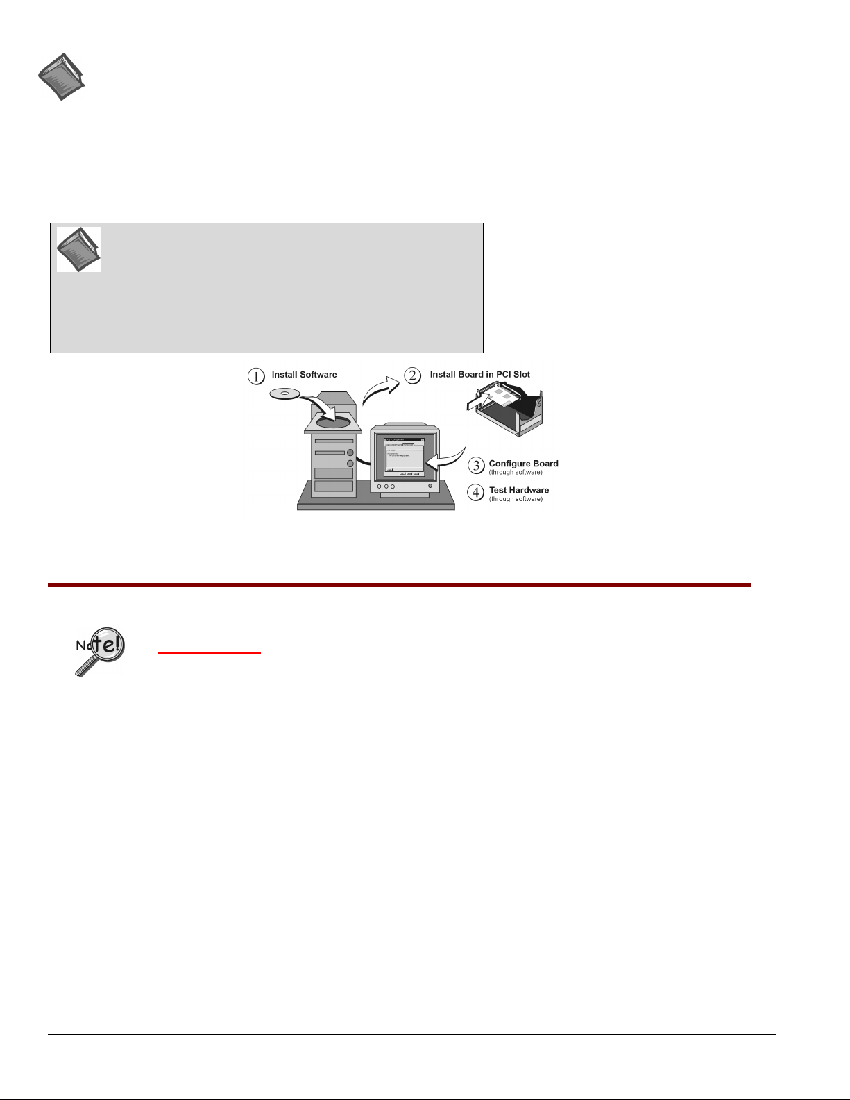
This guide tells you how to complete the following steps for a successful installation.
Step 1 – Install Software
Step 2 – Install Boards in Available PCI Bus-Slots
Step 3 – Configure Boards
Step 4 – Test Hardware
…… page 2
…… page 3
….. page 5
….. page 6
Reference Note:
After you have completed the installation you should refer to the electronic documents that
were automatically installed onto your hard drive as a part of product support. The default
location is in the Programs directory, which can be accessed from the Windows Desktop.
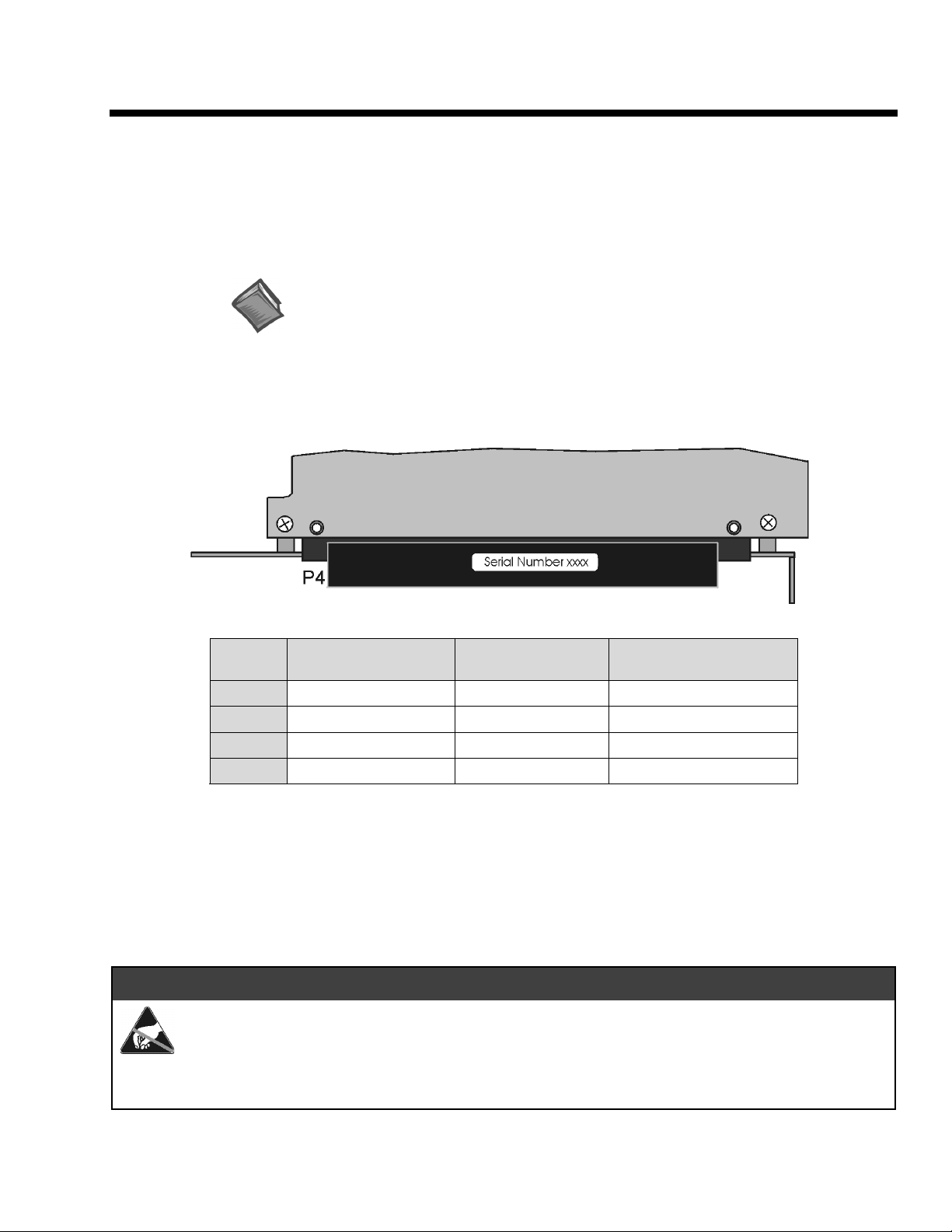
You should keep your DaqBoard/2000 Series board’s serial number and your DaqView/2000 authorization
code (if applicable) with this document. Space is provided below for recording up to 4 board numbers and
their PCI bus-slot location. The board serial number is located on the P4 connector as indicated
following figure.
Serial Number Location on DaqBoard/2000 Series P4 Connector
in the
Board Type (e.g., 2000,
2002, 2003, etc.)*
Board 1
Board 2
Board 3
Board 4
The host PC can support up to four DaqBoard/2000 Series Boards.
Serial Number PCI Bus-Slot Location
*Note: DaqBoard/2000 Series boards have device labels which read, for example, “DaqBoard/2000,” “DaqBoard/2001,”
“DaqBoard/2002,” etc. The name labels are convenient for users of more than one board type.
DaqView/2000 Authorization Code
Customers who ordered DaqView/2000 can find their authorization code on the
Note that earlier documents may refer to this as a “registration code” or “registration ID.”
Customers who did not order DaqView/2000 can run a
____________________________
30-day free trial version
authorization code sheet
, as discussed elsewhere in the User’s Manual.
located inside the sleeve of the install CD.
&$87,21
Take ESD precautions (packaging, proper handling, grounded wrist strap, etc.)
Use care to avoid touching board surfaces and onboard components. Only handle boards by their edges
(or ORBs, if applicable). Ensure boards do not come into contact with foreign elements such as oils,
water, and industrial particulate.
© 1999, 2000, 2001, 2002 by IOtech, Inc. October 2002
1033-0940
6.0
rev
,
.
IG-1
Page 12
Reference Notes:
(1) Each DaqBoard/2000 Series Board plugs into a PCI bus-slot. Consult your PC owner’s manual as needed.
(2) Be sure to read about the DBK cards and modules applicable to your acquisition system. Specific DBK information can
be found in on the world wide web at
Manual
(p/n 457-0905). After the install you can navigate to the DBK manual and other relevant electronic documents from
your desktop as follows:
Start ⇒ Programs ⇒ IOtech DaqX Software ⇒ DaqBoard 2000 Series Users
http://www.daqboard.com
; and in your
DBK Option Cards and Modules User’s
Minimum System Requirements
Reference Note
: Adobe PDF versions of user manuals will
automatically install onto your hard drive as a part of product
support. The default location is in the
can be accessed from the
Windows Desktop
Programs
group, which
. Refer to the PDF
documentation for details regarding both hardware and software.
Note that hardcopy versions of the manuals can be ordered from
the factory.
PC system with Pentium® Processor
Windows Operating System
RAM, as follows:
32 Mbytes of RAM for Windows 95/98/NT
64 Mbytes of RAM for Windows Me
64 Mbytes of RAM for Windows 2000
64 Mbytes of RAM for Windows XP
Step 1
DaqBoard/2000 Series Installation, A Pictorial Overview
– Install Software
IMPORTANT: Software must be installed before installing hardware.
Remove
1.
Programs
2. Place the Data Acquisition CD into the CD-ROM drive.
take a few moments, depending on your PC.
Start/Run/Browse feature.
3. After the intro-screen appears, follow the screen prompts.
Upon completing the software installation, continue with step 2,
previous version Daq drivers, if present. You can do this through Microsoft’s
feature.
Add/Remove
Wait for PC to auto-run the CD. This may
If the CD does not auto-run, use the Desktop’s
Install Boards in available PCI Bus-slots
.
IG-2 DaqBoard/2000 Series Installation Guide
10-17-02
1033-0940, rev 6.0
Page 13
Step 2
– Install Boards in available PCI Bus-slots
IMPORTANT: Software must be installed before installing hardware.
IMPORTANT: Bus Mastering DMA must be Enabled
For a DaqBoard/2000 Series board to operate properly, Bus Mastering DMA
Prior to installation, verify that your computer is capable of performing Bus Mastering DMA for
the applicable PCI bus-slot. Note that some computers have BIOS settings that enable [or disable]
Bus Mastering DMA. If your computer has this BIOS option, ensure that Bus Mastering DMA is
Enabled
Refer to your PC’s owner manual for additional information regarding Bus Mastering DMA.
on the appropriate PCI slot.
.
must be enabled
.
&$87,21
Turn off power to, and UNPLUG the host PC and externally connected equipment prior to
removing the PC’s cover and installing DaqBoard/2000. Electric shock or damage to equipment
can result even under low-voltage conditions.
Take ESD precautions (packaging, proper handling, grounded wrist strap, etc.)
Use care to avoid touching board surfaces and onboard components. Only handle boards by their
edges (or ORBs, if applicable). Ensure boards do not come into contact with foreign elements such
as oils, water, and industrial particulate.
IMPORTANT: Bus Mastering DMA must be Enabled
For a DaqBoard/2000 Series board to operate properly, Bus Mastering DMA
the PCI slot [for which the DaqBoard/2000 Series board is to be installed]. Prior to installation,
verify that your computer is capable of performing Bus Mastering DMA for the applicable PCI
slot. Note that some computers have BIOS settings that enable [or disable] Bus Mastering DMA.
If your computer has this BIOS option, ensure that Bus Mastering DMA is
appropriate PCI slot.
Refer to your PC Owner's Manual for additional information regarding your PC and enabling
Bus Mastering DMA for PCI slots.
.
must be
Enabled
Enabled on
on the
1. Turn
2. Remove the PC’s cover.
3. Choose an available PCI bus-slot.
4. Carefully remove DaqBoard/2000 Series Board from its anti-static protective bag. If you have not already done so, write
down the serial number of your board at this time. See inside front cover for details.
1033-0940, rev 6.0
power to, and
off
UNPLUG the host PC
Refer to your PC Owner’s Manual as needed
and externally connected equipment.
10-17-02
.
DaqBoard/2000 Series Installation Guide IG-3
Page 14
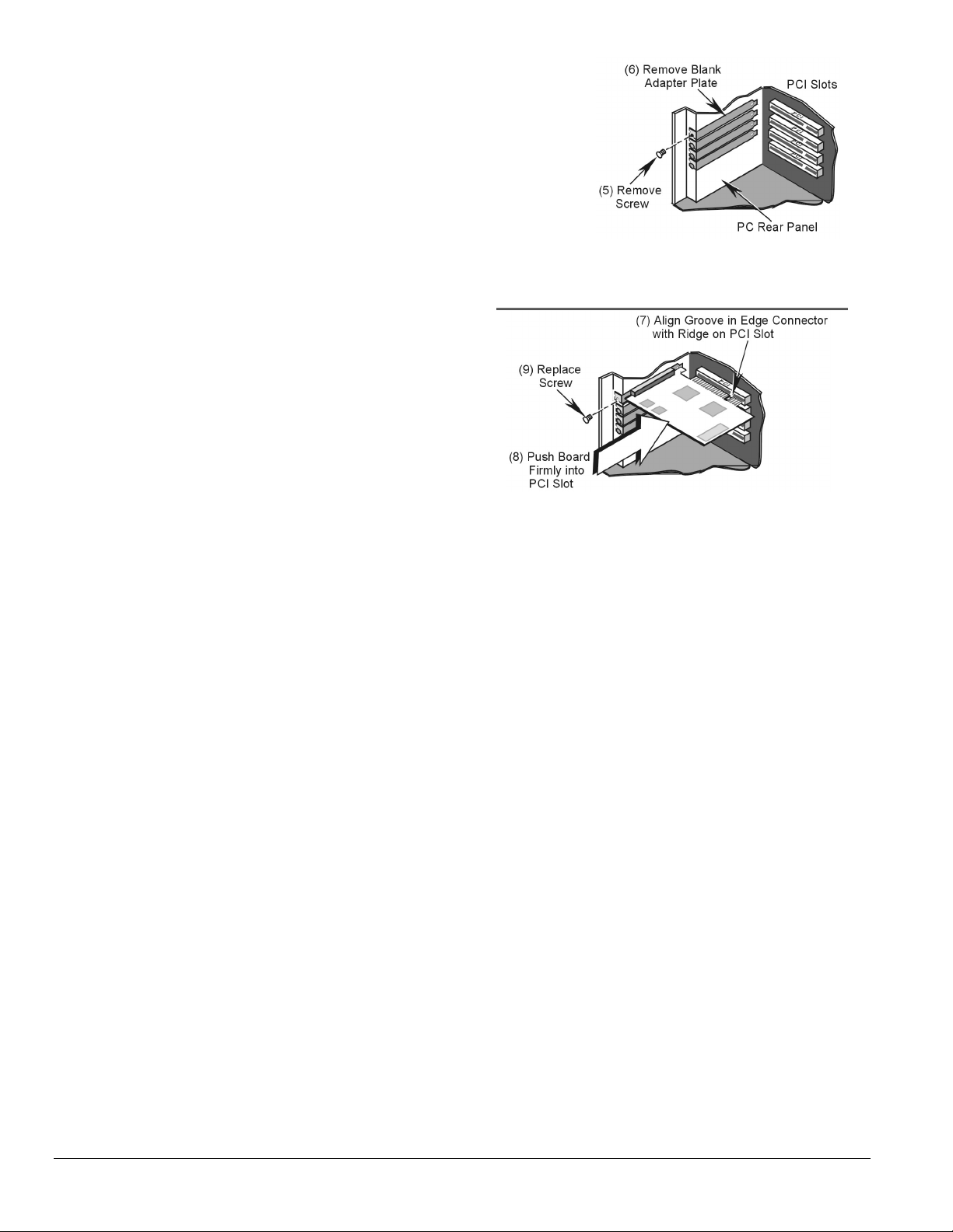
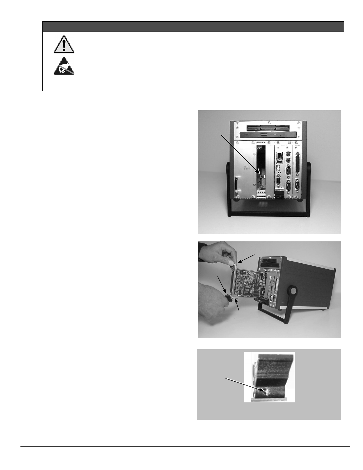
5. On the PC’s rear panel, loosen and remove the screw for the blank adapter
plate that corresponds with the chosen PCI bus.
6. Remove the adapter plate for the chosen PCI slot.
Refer to your PC Owner’s Manual if needed
.
7. Align groove in the DaqBoard/2000 Series board’s PCI edge-connector with
the ridge of the desired PCI slot, and with the PC’s corresponding rear-panel
slot.
8. Push the board firmly into the PCI slot. The board will snap into position.
9. Secure the board by inserting the rear-panel adapter-plate screw.
10. Using the previous steps, install additional boards into available PCI bus-slots,
if applicable to your application.
11. Replace the computer’s cover.
12. Plug in all cords and cables that were removed in step 1.
13. Apply power to, and start up the PC.
Note
: At this point some PCs may prompt you to insert an
installation disk. While this is rare, if you do receive such a
prompt simply place the install CD-ROM into the disk drive
and follow additional screen prompts.
Installing a DaqBoard/2000 Series Board
Removing a Blank Adapter Plate
IG-4 DaqBoard/2000 Series Installation Guide
10-17-02
1033-0940, rev 6.0
Page 15
Step 3
– Configure Boards
DaqBoard/2000 Series Boards have no jumpers or switches to set. Configuration is performed, in its
entirety, through software. Refer to the following figure and steps to complete the configuration. The
numbers in the figure correspond to the numbered steps immediately following the figure.
1033-0940, rev 6.0
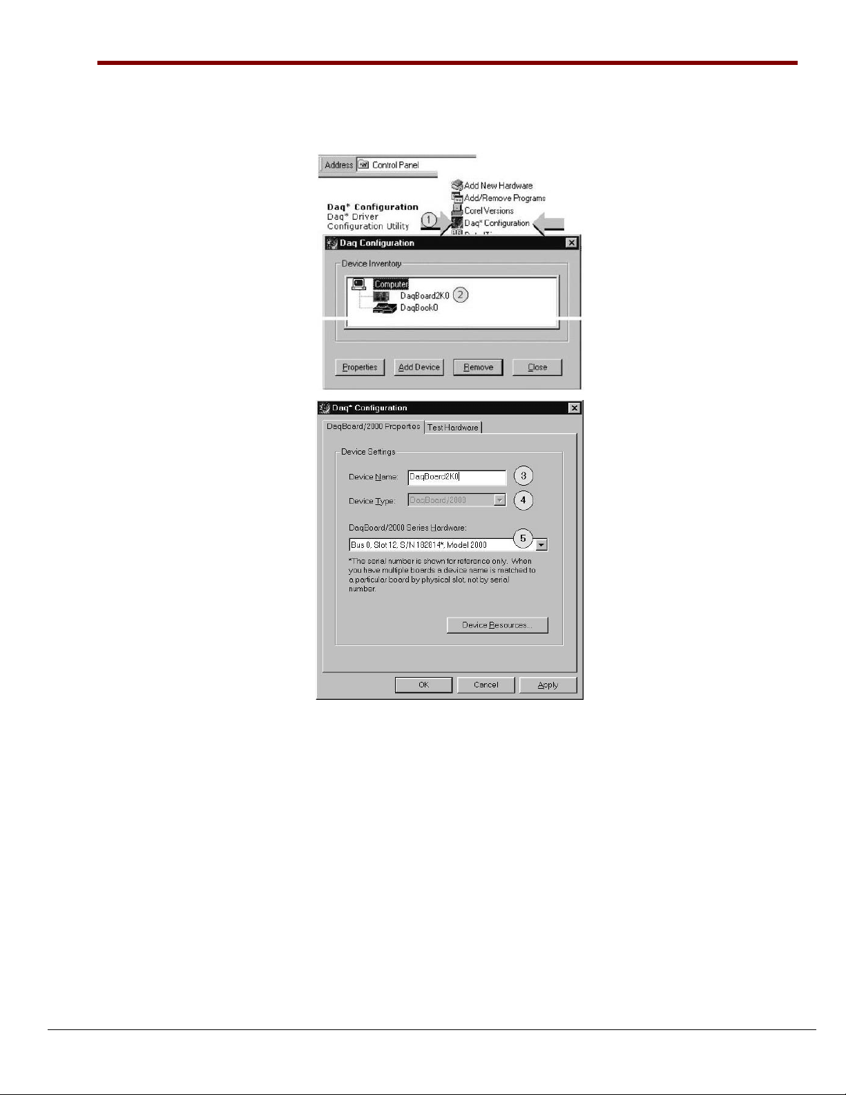
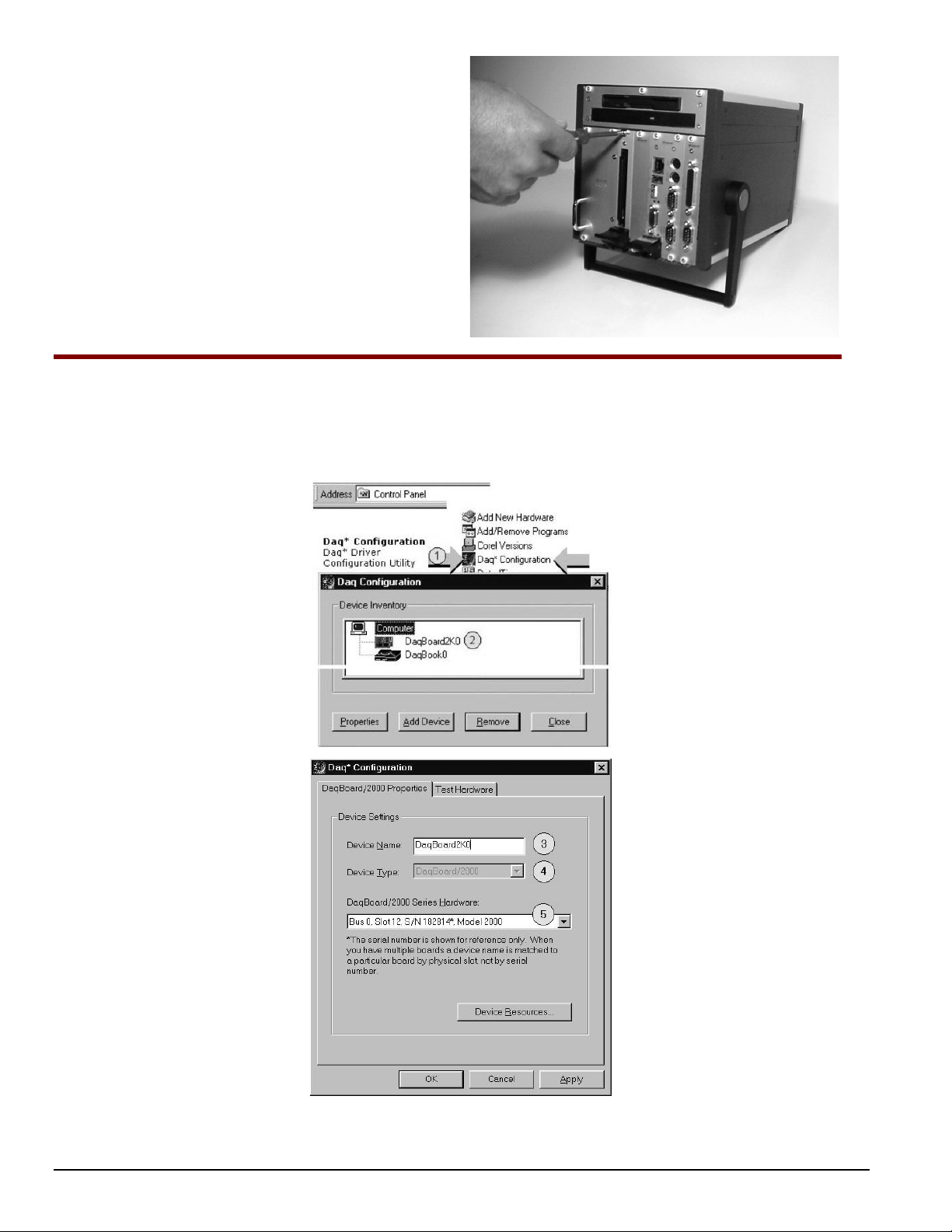
Accessing the DaqBoard/2000 Properties Tab
1. Run the
Daq Configuration
control panel applet. Navigation from the desktop to the applet is as follows:
Start ⇒ Settings ⇒ Control Panel ⇒ Daq*Configuration (double-click)
2. Double-click on the Device Inventory’s DaqBoard2K0 icon. The DaqBoard/2000 Properties tab (used for the
entire DaqBoard/2000 Series) will appear.
If the DaqBoard2K0 icon is not present, skip to the Using ‘Add
Device’ section provided below.
3. Enter a “
Device Name
” in the text box, or use the default “DaqBoard2K0.” Device Name is for identifying the
specific DaqBoard/2000 Series board. Note that Device Name actually refers to the PCI slot and not to the
actual board.
4. Verify that the “Device Type” shows the correct DaqBoard/2000 Series board, e.g., “DaqBoard/2000,
DaqBoard/2001, etc.” Note that available device types can be viewed via the pull-down list (▼).
5. Confirm that the DaqBoard/2000 Series text box shows a
If this text box is empty
, use its pull-down list (▼) and select the serial number that matches the one for your
Bus #, Slot #,
Serial Number
and
.
board.
Refer to the inside front cover page for serial number information.
10-17-02
DaqBoard/2000 Series Installation Guide IG-5
Page 16
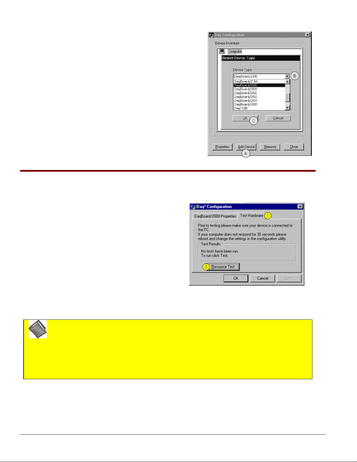
Using “Add Device”
This method is for users who have accessed the
control panel applet, but have no DaqBoard2K icon (as described on
page 3, step 2).
(A) After accessing the Daq Configuration control panel applet, click on
the Add Device button (see figure, right). The
window will appear.
(B) Using the
In the example at the right
Device Type’s
pull-down list, select the applicable board.
DaqBoard/2000
(C) Click the OK button. The DaqBoard/2000 Properties tab will appear.
This tab applies to all boards in the DaqBoard/2000 Series.
At this point, complete steps 3 through 5 from page 3.
Daq Configuration
Select Device Type
is selected.
Using “Add Device”
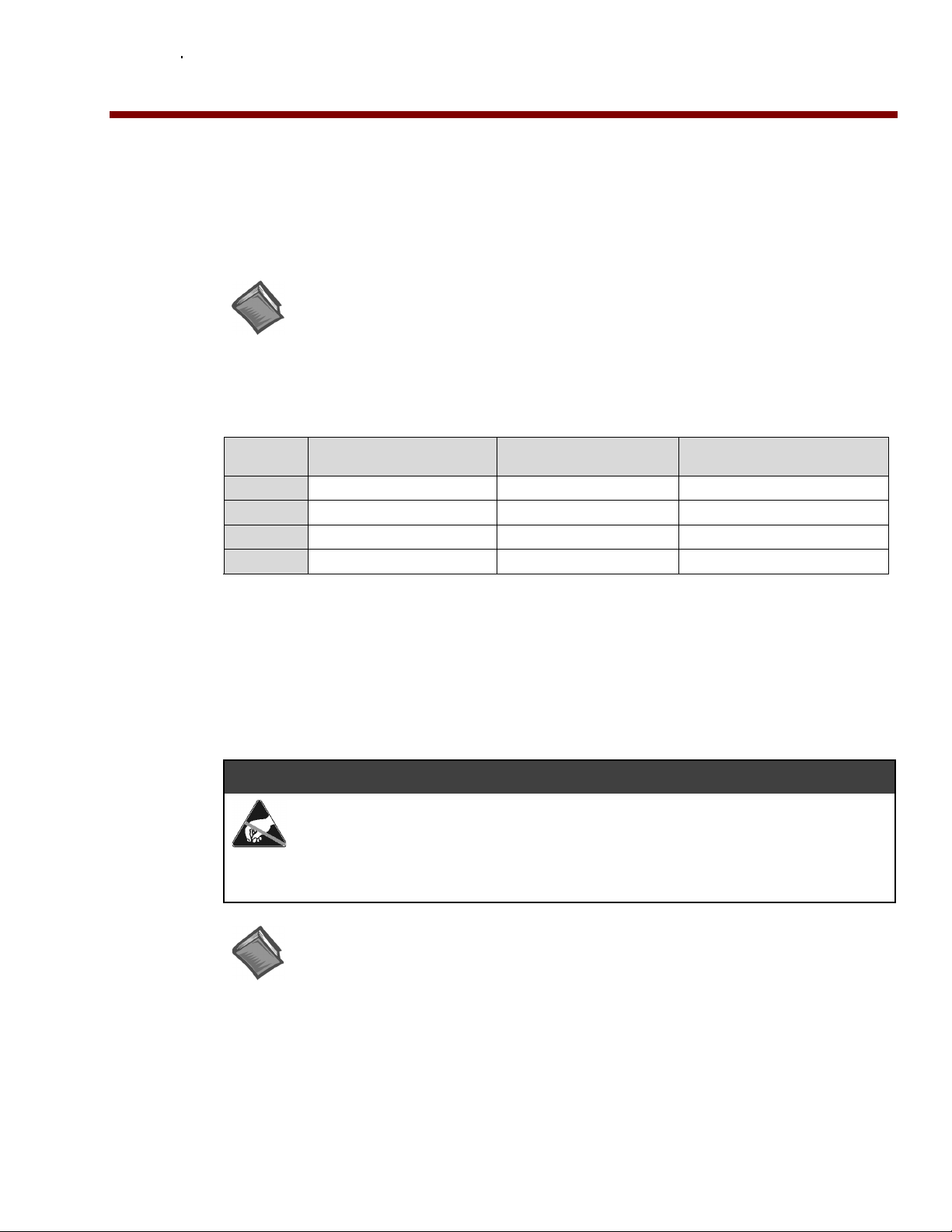
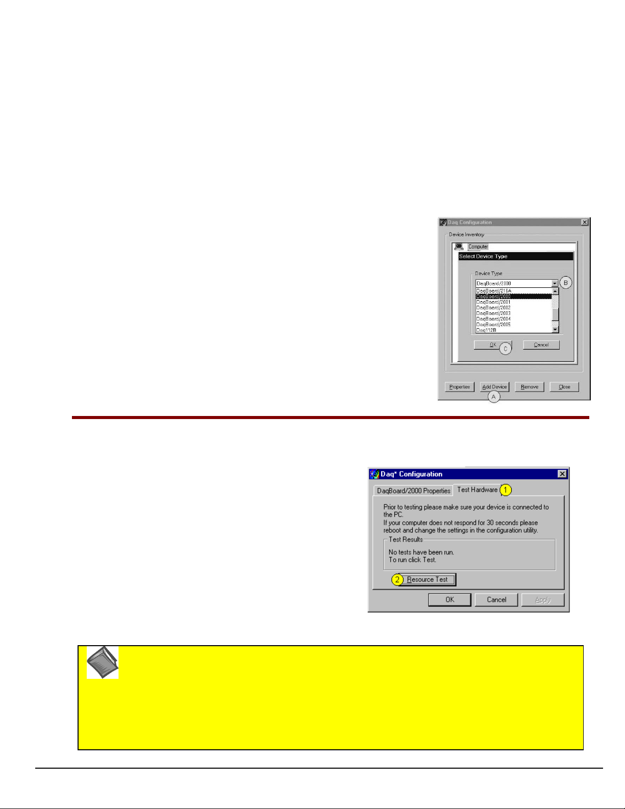
Step 4
– Test Hardware
Use the following steps to test the DaqBoard/2000 Series board. Note that these steps are continued from those listed under
the previous section, “Configure Board.”
1. Select the “
2. Click the “
Test Hardware”
Resource Test
” button.
tab.
3. After the test is complete, click “OK.”
System capability is now tested for the DaqBoard/2000
Series board and a list of test results appears on screen.
Note:
If you experience difficulties, please consult your user
documentation (included on your CD) before calling for
technical support. Note that the user documentation
includes a troubleshooting chapter, as well as a great
deal of information regarding specific DBK cards and
modules.
Test Hardware Tab
(Condensed Screen Image)
At this point we are ready to connect signals. This is typically accomplished with the use of a DBK200 Series option.
Reference Note
For detailed information regarding the DBK200 Series options, refer to the
User’s Manual
:
DBK Option Cards and Modules
(p/n 457-0905).
During software installation, Adobe® PDF versions of user manuals are automatically installed onto your hard
drive as a part of product support. The default location is in the
from the Windows Desktop. A copy of the Adobe Acrobat Reader® is included on your CD. The Reader
provides a means of reading and printing the PDF documents. Note that hardcopy versions of manuals can be
ordered from the factory.
IG-6 DaqBoard/2000 Series Installation Guide
10-17-02
Programs
directory, which can be accessed
1033-0940, rev 6.0
Page 17

1033-0940, rev 6.0
10-17-02
DaqBoard/2000 Series Installation Guide IG-7
Page 18

IG-8 DaqBoard/2000 Series Installation Guide
10-17-02
1033-0940, rev 6.0
Page 19
DaqBoard/2000c Series Installation
This guide tells you how to complete the following steps for a successful installation.
Step 1 – Install Software
Step 2 – Install Boards into Available, 5 Volt, Compact-PCI Bus-Slots
Step 3 – Configure Boards
Step 4 – Test Hardware
…… page 2
…… page 2
….. page 4
….. page 5
Reference Note:
After you have completed the installation you should refer to the electronic documents that
were automatically installed onto your hard drive as a part of product support. The default
location is in the Programs directory, which can be accessed from the Windows Desktop.
You should keep your DaqBoard/2000c Series board’s serial number and your DaqView/2000 authorization
code (if applicable) with this document. Space is provided below for recording up to 4 board numbers and
their compact-PCI bus-slot location. Board serial numbers are located on the 100-pin P4 connector.
Board Type
e.g., DaqBoard/2005c
Board 1
Board 2
Board 3
Board 4
Compact PC support for DaqBoard/2000c Series boards varies. A system can support no more than four boards.
Serial Number Compact-PCI Bus-Slot Location
*Note: The DaqBoard/2000c Series boards have their board identity indicated on the latch, as indicated in
the photo on the front page of this guide. This identification is provided since the boards look very
much alike and are visually identical once installed.
DaqView/2000 Authorization Code
Customers who ordered DaqView/2000 can find their authorization code on the
sleeve of the install CD. Customers who did not order DaqView/2000 can run a
user’s manual.
____________________________
&$87,21
Take ESD precautions (packaging, proper handling, grounded wrist strap, etc.)
Use care to avoid touching board surfaces and onboard components. Only handle
boards by their edges (or ORBs, if applicable). Ensure boards do not come into contact
with foreign elements such as oils, water, and industrial particulate.
Reference Note:
During software installation, Adobe
onto your hard drive as a part of product support. The default location is in the Programs
directory, which can be accessed from the Windows Desktop. A copy of the Adobe Acrobat
®
Reader
is included on your CD. The Reader provides a means of reading and printing the
PDF documents. Note that hardcopy versions of manuals can be ordered from the factory.
Note: In regard to functionality, the DaqBoard/2000c Series boards are identical to their
DaqBoard/2000 Series counterparts.
®
PDF versions of user manuals are automatically installed
authorization code sheet
30-day free trial version
located inside the
, as discussed in the
© 2001, 2002 by IOtech, Inc. October 2002
1061-0940
,
rev.
3.0
IG-1
Page 20
Reference Notes:
➣
Each DaqBoard/2000c Series Board plugs into a 5 volt, compact-PCI bus-slot located on the PC’s backplane. Note that
the 5 V compact-PCI bus-slot contains a blue key (see page 3). Consult your PC owner’s manual as needed.
➣
Be sure to read about the DBK cards and modules applicable to your acquisition system. Specific DBK information can
be found in on the world wide web at http://www.daqboard.com; and in your
Manual
(p/n 457-0905). After the install you can navigate to the DBK manual and other relevant electronic documents
from your desktop as follows:
Start ⇒ Programs ⇒ IOtech DaqX Software ⇒ DaqBoard 2000 Series Users
Reference Note
automatically install onto your hard drive as a part of product
support. The default location is in the
can be accessed from the
documentation for details regarding both hardware and software.
Note that hardcopy versions of the manuals can be ordered from
the factory.
: Adobe PDF versions of user manuals will
Programs
Windows Desktop
group, which
. Refer to the PDF
DBK Option Cards and Modules User’s
Minimum System Requirements
PC system with Pentium® Processor
Windows Operating System
RAM, as follows:
32 Mbytes of RAM for Windows 95/98/NT
64 Mbytes of RAM for Windows Me
64 Mbytes of RAM for Windows 2000
64 Mbytes of RAM for Windows XP
Step 1
Step 2
– Install Software
IMPORTANT: Software must be installed before installing hardware.
Remove
1.
Programs
2. Place the Data Acquisition CD into the CD-ROM drive.
take a few moments, depending on your PC.
Start/Run/Browse feature.
3. After the intro-screen appears, follow the screen prompts.
Upon completing the software installation, continue with step 2,
Compact-PCI Bus-slots
previous version Daq drivers, if present. You can do this through Microsoft’s
feature.
Wait for PC to auto-run the CD. This may
If the CD does not auto-run, use the Desktop’s
Install Boards in available 5 Volt,
.
– Install Boards in available 5 Volt, Compact-PCI Bus-slots
IMPORTANT: Software must be installed before installing hardware.
IMPORTANT: Bus Mastering DMA
For a DaqBoard/2000c Series board to operate properly, Bus Mastering DMA
Prior to installation, verify that your computer is capable of performing Bus Mastering DMA for
the applicable compact-PCI bus-slot. Note that some computers have BIOS settings that enable
[or disable] Bus Mastering DMA. If your computer has this BIOS option, ensure that Bus
Mastering DMA is
Refer to your PC’s owner manual for additional information regarding Bus Mastering DMA.
Enabled
on the appropriate compact-PCI bus-slot.
must be
Enabled
.
must be enabled
Add/Remove
.
IMPORTANT: The Compact-PCI Bus-Slot must be keyed for 5 Volt use.
Note
: The 5 Volt Key location is indicated in the first photograph on page 3.
IG-2 DaqBoard/2000c Series Installation Guide
10-17-02
1061-0940, rev 3.0
Page 21
&$87,21
Turn power OFF, and UNPLUG the host PC and externally connected equipment prior to
removing any cover plates or modules. Electric shock or damage to equipment can result even
under low-voltage conditions.
Take ESD precautions (packaging, proper handling, grounded wrist strap, etc.)
Use care to avoid touching board surfaces and onboard components. Only handle boards by their
edges or ORBs. Ensure boards do not come into contact with foreign elements such as oils, water,
and industrial particulate.
1. Turn the PC’s power
2. Turn
3.
power OFF
UNPLUG the host PC
OFF
.
to externally connected equipment.
and all externally connected
equipment.
4. Remove the computer’s compact-PCI bus-slot cover plate
[or remove an unwanted module, if applicable].
Refer to your PC Owner’s Manual as needed
.
5. Verify that the available compact-PCI bus slot is for
5 volt applications.
The computer’s 5 volt compact-PCI bus-slots can be
recognized by a blue voltage key that is located in the
center of the slot (see figure).
6. Carefully remove the DaqBoard/2000c Series Board from
its anti-static protective bag. If you have not already done
so, write down the serial number of your board at this
time. The serial number is located on the 100-pin P4
connector.
7. With the board’s
injector/ejector
down, guide the board
into the PC’s slot. Note that the top and bottom edges of
the board locate in edge-guides, within the PC.
8. Push the board back into the PC to engage the board’s
compact-PCI connector with the computer’s compact-PCI
bus-slot.
9. Pull the board’s
injector/ejector
up. This will fully
engage the connectors.
10. Secure the board by tightening the upper and lower lock
screws.
11. Using the previous steps, install additional boards into
available compact-PCI bus-slots, if applicable to your
application.
Note
: The lower lock screw is accessed through an opening
injector/ejector
on the
as indicated in the right-hand
figure.
Voltage
Key
Compact-PCI Bus-Slot with Blue 5 Volt Identifier Key
Upper Lock Screw
Injector/
Ejector
Lower Lock Screw
(see note)
Installing a DaqBoard/2000c Series Board
Lower Lock
Screw
1061-0940, rev3.0
10-17-02
Injector/Ejector and Lower Lock Screw
DaqBoard/2000c Series Installation Guide IG-3
Page 22
12. Plug in all cords and cables that were removed in step 3.
q
13. Apply power to, and start up the PC.
Note
: At this point some PCs may prompt you to insert an
installation disk. While this is rare, if you do receive
such a prompt simply place the install CD into the disk
drive and follow the screen prompts.
Board/2000c Series Board
Step 3
Securing a Da
– Configure Boards
DaqBoard/2000c Series boards have no jumpers or switches to set. Configuration is performed entirely through software.
Refer to the following figure and steps to complete the configuration. The numbers in the figure correspond to the numbered
steps immediately following the figure.
Accessing the DaqBoard/2000 Properties Tab
IG-4 DaqBoard/2000c Series Installation Guide
10-17-02
1061-0940, rev 3.0
Page 23
1. Run the
Start ⇒ Settings ⇒ Control Panel ⇒ Daq*Configuration (double-click)
2. Double-click on the Device Inventory’s DaqBoard2K0 icon. The DaqBoard/2000 Properties tab (used for the entire
DaqBoard/2000 Series) will appear.
provided below.
3. Enter a “
DaqBoard/2000 Series board. Note that Device Name actually refers to the PCI slot and not to the actual board.
4. Verify that the “Device Type” shows the correct DaqBoard/2000 Series board, e.g., “DaqBoard/2000, DaqBoard/2001, etc.”
Note that available device types can be viewed via the pull-down list (▼).
5. Confirm that the DaqBoard/2000 Series text box shows a
If this text box is empty
Refer to the inside front cover page for serial number information.
Daq Configuration
Device Name
” in the text box, or use the default “DaqBoard2K0.” Device Name is for identifying the specific
, use its pull-down list (▼) and select the serial number that matches the one for your board.
control panel applet. Navigation from the desktop to the applet is as follows:
If the DaqBoard2K0 icon is not present, skip to the Using ‘Add Device’ section
Bus #, Slot #,
Serial Number
and
.
Using “Add Device”
This method is for users who have accessed the
applet, but have no DaqBoard2K icon (as described in
step 2, above).
(A) After accessing the Daq Configuration control panel applet, click on the Add
Device button (see figure, right). The
(B) Using the
example at the right
(C) Click the OK button. The DaqBoard/2000 Properties tab will appear. This tab
applies to all boards in the DaqBoard/2000 Series.
At this point, complete steps 3 through 5 from above.
Device Type’s
DaqBoard/2000
pull-down list, select the applicable board. In the
Daq Configuration
Select Device Type
is selected.
control panel
window will appear.
Using “Add Device’
Step 4
Use the following steps to test the DaqBoard/2000 Series board. Note that these steps are continued from those listed under
the previous section, “Configure Board.”
Note:
At this point we are ready to connect signals. This is typically accomplished with the use of a DBK200 Series option.
–
Test Hardware
1. Select the “
2. Click the “
3. After the test is complete, click “OK.”
System capability is now tested for the DaqBoard/2000
Series board and a list of test results appears on screen.
If you experience difficulties, please consult your user
documentation (included on your CD) before calling for
technical support. Note that the user documentation
includes a troubleshooting chapter, as well as a great
deal of information regarding specific DBK cards and
modules.
Test Hardware”
Resource Test
Reference Note
For detailed information regarding the DBK200 Series options, refer to the
User’s Manual
During software installation, Adobe® PDF versions of user manuals are automatically installed onto your hard
drive as a part of product support. The default location is in the
from the Windows Desktop. A copy of the Adobe Acrobat Reader® is included on your CD. The Reader
provides a means of reading and printing the PDF documents. Note that hardcopy versions of manuals can be
ordered from the factory.
:
(p/n 457-0905).
tab.
” button.
Test Hardware Tab (Condensed Screen Image)
DBK Option Cards and Modules
Programs
directory, which can be accessed
1061-0940, rev3.0
10-17-02
DaqBoard/2000c Series Installation Guide IG-5
Page 24

IG-6 DaqBoard/2000c Series Installation Guide
10-17-02
1061-0940, rev 3.0
Page 25

1061-0940, rev3.0
10-17-02
DaqBoard/2000c Series Installation Guide IG-7
Page 26

IG-8 DaqBoard/2000c Series Installation Guide
10-17-02
1061-0940, rev 3.0
Page 27

Daq Systems and Device Overviews 1
Daq Systems, the Modular Concept …… 1-1
DaqBooks, DaqBoards, and Daq PC-Cards …… 1-2
Theory of Operation, DaqBoard/2000 Series and /2000c Series Boards …… 1-4
DaqBoard/2000 and /2000c ….… 1-9
DaqBoard//2001 and /2001c……. 1-11
DaqBoard//2002 and /2002c…… 1-13
DaqBoard//2003 and /2003c…… 1-15
DaqBoard//2004 and /2004c…… 1-17
DaqBoard//2005 and /2005c…… 1-19
Using DBK Cards and Modules for Signal Conditioning ….. 1-21
Daq Software ……1-21
DaqBoard/2000 Series and /2000c Series Boards
Specifications -
Daq Systems, the Modular Concept
Daq equipment and software form a modular, interrelated family of products that provide great flexibility in
data acquisition system design. This flexibility allows for the development of custom systems that are
unique to the user, and which can be optimized for his or her specific application needs. With the Daq
product line, system expansion or redesign can typically be accomplished with relative ease.
……
1-23
•
Primary Acquisition Device. This is the main data acquisition device, e.g., a DaqBook, DaqBoard,
or Daq PC-Card. These devices provide a vital data conversion and communications link between
the data source of transducers and signal conditioners and the data processor of the host computer.
Note the DaqBoards can be one of three types: (1) ISA, (2) PCI, or (3) compact-PCI.
•
DBK Option Cards and Modules. Over 35 DBK cards and modules (the number is constantly
growing) provide various types of signal conditioning and system expansion. Note that certain DBK
modules exist for the purpose of supplying power to other members of the acquisition system. The
DBK options are discussed in a DBK Basics document module and in the detailed DBK Option Cards
and User’s Manual (p/n 457-0905).
Note: Only passive DBKs, such as the DBK1 BNC module, the DBK11A screw terminal card, and
the DBK40 BNC analog interface, can be used with a Daq PC-Cards.
Reference Note:
DBK options are discussed in the DBK Option Cards and Modules User’s Manual
(p/n 457-0905). As a part of product support, this manual is automatically loaded onto
your hard drive during software installation. The default location is the Programs
directory, which can be accessed through the Windows Desktop.
•
Software. DaqView out-of-the-box software provides a graphical user interface with easy to read
spreadsheet formats for viewing channel data, as well as a choice of analog, digital, and bar-graph
meters. Waveform analysis can be performed, when applicable. A product support option, included
on the data acquisition CD, provides a means of performing post data analysis. More information is
included in the software-specific PDF documents that are installed on your hard-drive as a part of
product support.
DaqBoard/2000 Series & /2000c Series User’s Manual
10-18-02
Daq Systems and Device Overviews 1-1
Page 28

In addition to the included out-of-the-box software, Daq products can be controlled via user-written
custom programs through Applications Program Interface (API). Several languages are supported,
e.g., C/C++, VisualBASIC, Delphi.
DaqView and DASYLab can only be used with one DaqBoard/2000 Series board or
/2000c Series board at a time. LabView can be used with multiple boards.
For multiple board use (via custom programming) refer to the Using Multiple
Devices section of the Programmer’s Manual. During software installation from the
data acquisition CD (p/n 1022-0601), a PDF version of the Programmer’s Manual is
automatically loaded onto your hard drive as a part of product support. The
default location is the Programs directory.
Reference Note:
Programming topics are covered in the Programmer’s User Manual (p/n 1008-0901).
As a part of product support, this manual is automatically loaded onto your hard drive
during software installation. The default location is the Programs directory, which can
be accessed through the Windows Desktop.
DaqBooks, DaqBoards and Daq PC-Cards
Daq products connect to one or more DBKs on their signal input side and a computer on their output side.
Each type of Daq device connects to the computer in a different way:
•
The DaqBook is an external module that connects to a computer’s enhanced parallel port (EPP)
interface or PC-Card link.
•
The DaqBoard [ISA type] board is an internal card that plugs into an ISA-bus slot within a
computer.
•
DaqBoard/2000 Series Boards plug into a PCI-bus slot, within a host PC.
•
DaqBoard/2000c Series boards plug into a compact-PCI-bus slot, within a host PC.
•
The Daq PC-Card slides into the PCMCIA slot of a host computer, typically a notebook PC.
Features common to the Daq products include:
•
100-kHz channel-to-channel scan and gain switching (10 µs);
200-kHz for DaqBoard/2000 Series and DaqBoard/2000c Series Boards.
•
512-location sequence memory that can be loaded with any combination of channels and gains.
•
Ability to access up to 256 different channels of DBK signals while maintaining the channel-tochannel scan rate. The DBK expansion options can accommodate mixed-signal inputs from
thermocouples and RTDs to isolated high-voltage inputs and strain gages.
•
Ability to handle 8 differential or 16 single-ended signal inputs without DBK expansion units.
•
Ability to handle fixed digital I/O up to 4 TTL lines in and 4 TTL lines out (accessible only if no
analog expansion cards are in use).
1-2 Daq Systems and Device Overviews
10-18-02
DaqBoard/2000 Series & /2000c Series User’s Manual
Page 29

Daq Data Acquisition Devices
Category Device Description
Primary
Acquisition
Device
DBK Option
Cards and
Modules
Software
DaqBook*
DaqBoard/2000
Series
DaqBoard/2000c
Series
DaqBoard (ISA types)*
Daq PC-Card*
Analog Signal
Conditioning
Analog Output
Digital I/O and Control
Expansion
Connections
Power Supply DBKs: 30A, 32A, 33, 34
Included Software DaqView, Post Data Acquisition Analysis Program (actual application not
Optional Software DaqView/2000, DaqViewXL, DASYLab
Portable Data Acquisition Modules
12-bit: DaqBook/100, /112, /120
16-bit: DaqBook/200, /216, /260
Plug-In Boards for PCI Bus-Slots
16-bit , 200 kHz. Six boards identified as /2000 through /2005
Plug-In Boards for Compact-PCI Bus-Slots
16-bit , 200 kHz. Six boards identified as /2000c through /2005c
Plug-In Boards for ISA Bus-Slots
12-bit: DaqBoard/100A, /112A
16-bit: DaqBoard/200A, /216A, /2000
Plug-In PCMCI Card
12-bit: Daq/112B
16-bit: Daq/216B
Cards and modules used to condition Analog Signals
DBK/ 4, 7, 8, 9, 12, 13, 15, 17, 18, 19, 42, 43A, 44, 45, 50, 51, 52, 53, 54,
207, 207/CJC
Cards used to modify Analog Output Signals
DBK/ 2, 5
Cards and modules used to condition Digital I/O
DBK/ 20, 21, 23, 24, 25, 208
Cards and modules used to expand the acquisition system.
DBK/ 1, 10, 11A, 35, 40, 41, 60, 200, 201, 202, 203, 204, 205, 206, 209
specified), Visual Basic extensions, Application Programming Interface
(API)
DaqBoard/2000 Series & /2000c Series User’s Manual
10-18-02
Daq Systems and Device Overviews 1-3
Page 30

Theory of Operation
As implied by the following matrix, the operational material does not apply globally to every
DaqBoard/2000 Series board or /2000c Series board. For example, boards /2002, /2003, /2004, and their
respective compact-PCI counterparts have no analog input.
For ease of understanding, each board is discussed independently, following the matrix. Note that pinouts
are provided in chapter 2.
I/O Comparison Matrix
I/O Comparison Matrix
for DaqBoard/2000 and /2000c Series Boards
for DaqBoard/2000 and /2000c Series Boards
DaqBoard/
(PCI and
compact-PCI
versions)
2000 and
2000c
2001 and
2001c
2002 and
2002c
2003 and
2003c
Analog Input
Channels
Analog Input signals enter
through P4 , go to MUX, to
PGA, to Gain & Offset
Amplifier, then to Analogto-Digital Converter (ADC)
16
16
-- --
--
Analog Output
Channels
Digital Signals go through
Digital-to-Analog
Converters, then through
“DAC Out” on P4.
2
4
4
Digital I/O
Channels
Digital signals pass
through one 16-bit
Digital I/O Port and
three 8-bit Digital I/O
Ports located on P4.
40
40
40
-- --
Counter/
Timers
Four 16-bit Counter
Input signals and Two
16-bit Timer Output
signals via P4 and
System Controller.
6
6
6
2004 and
2004c
2005 and
2005c
1-4 Daq Systems and Device Overviews
16
--
4
40
6
--
10-18-02
40
DaqBoard/2000 Series & /2000c Series User’s Manual
6
Page 31

Synchronous Input Operations
The DaqBoard/2000 Series and /2000c Series products allow synchronous scanning and acquisition of
Analog Input, Digital Input and Counter Input Data at up to 200kHz aggregate scanning rates. The Analog
Input data can be either main unit or expansion modules from P1 compatible analog input modules. The
Digital Input data can be main unit 8-bit P2 (8255) digital inputs, 16-bit P3 digital inputs or P2 compatible
DBK digital input expansion modules.
Analog Input Channels
The DaqBoard/2000 Series boards and /2000c Series boards that offer analog input (see matrix) allow
analog input configuration for the board as well as the P1 compatible DBK analog input expansion
modules.
Channel Selection and Mode Settings
The main unit accepts up to 16 single ended or up to 8 differential-ended inputs and can be programmed for
single-ended or differential-ended on a per channel basis. Just one analog channel is sacrificed when a
DBK expansion module is enabled. See DBK documentation in the DBK Option Cards & Modules User’s
Manual (p/n 457-0905) for further information.
Channel Range and Polarity
Each main unit channel also may be programmed for either unipolar or bipolar mode with gain settings of
1,2,4,8,16,32 and 64.
Channel Sampling Interval
The DaqBoard/2000 Series and /2000c Series boards allow programmable sampling intervals of 5us or 10us
on a per channel basis. This mode allows some channels which change slowly but a higher degree of
accuracy is desirable to be sampled at a longer interval while channels that change more rapidly to be
sampled using a shorter interval. Each 5us or 10us interval reduces the maximum aggregate acquisition rate
for the entire scan by that amount.
Digital Input Channels
The DaqBoard/2000 Series and /2000c Series boards allow either synchronous scanning of digital input
channels or asynchronous I/O operations for all configured digital channels.
Counter Input Channels
The DaqBoard/2000 Series and /2000c Series boards allow synchronous scanning of the 4 16-bit counter
input channels. The four 16-bit counter channels can also be cascaded into two 32-bit counter channels.
For either cascaded or non-cascaded counter channels each channel can be configured for:
•
Pulse Counting Mode – specifies that each counter should be cleared upon being read and placed into
the input scan.
•
Totalize Counting Mode – specifies that each counter is to free-run and not be cleared during the input
acquisition.
Synchronous Input Acquisition Clocking
The DaqBoard/2000 Series and /2000c Series boards allow clocking of the synchronized inputs either by an
internal, programmable pacer clock or by external clocking. These products use a sequencer to implement a
multiplexing approach to gathering the input data. This means that with either internal or external clocking
the entire channel scan (including the sampling time for each channel) may not exceed the maximum
aggregate rate of 200kHz.
DaqBoard/2000 Series & /2000c Series User’s Manual
10-18-02
Daq Systems and Device Overviews 1-5
Page 32

Synchronous Output Operations
The DaqBoard/2000 Series and /2000c Series boards allow synchronous output of any D/A or P3 16-bit
Digital channels available at up to 100kHz for each channel. All D/A channels available and the 16-bit P3
Digital channel may have output streamed to them and clocked out synchronously. The D/A channels may
be configured for waveform output and the P3 digital channel may be configured for streamed digital
pattern output using the same clock sources.
Output Channel Configuration
Analog Output Channels
Each D/A channel can be configured for waveform output individually. If the D/A channel is not
configured for waveform output it then is available for asynchronous output operations.
Digital Pattern Output Channel
The 16-bit P3 Digital Port can be configured for streamed digital pattern output. If not configured for
streamed digital pattern output operations it then may be used for asynchronous digital I/O operations.
Synchronous Output Clocking
The DaqBoard/2000 Series and the /2000c Series boards allow clocking of the synchronized output by the
acquisition clock source, an internal, programmable pacer clock or by an external clock source. When the
clock source generates a new clock signal all outputs are updated concurrently. Regardless of the clock
source, the clock may not exceed the maximum update rate of 100kHz.
Synchronous Output Data Source
The DaqBoard/2000 Series and /2000c Series boards allow the data source for synchronized output
operations to be that of a memory based buffer or a file located on a mass storage medium. With either type
of output data source, the output data for all the channels are contained in the buffer and/or file. The file
path may be any file located on the on the machine or network accessible file.
Asynchronous I/O Operations
The DaqBoard/2000 Series and /2000c Series boards allow asynchronous input of any counter or digital
channel that is not currently configured for synchronous acquisition. The boards also allow for
asynchronous output to any D/A channels not currently configured for waveform output. Likewise, the
16-bit P3 digital port can be used for both asynchronous input and output operations if it is not currently
configured for streamed pattern output operations. In addition, the timer outputs can be programmed at any
time regardless of the current state of synchronous or asynchronous operations on other channels.
Digital I/O Channels
Local 8255 Channels
The DaqBoard/2000 Series and /2000c Series boards [which have digital I/O capabilities] have an
implemented Intel 8255 core in the digital I/O logic on the P2 port of the product. With the Intel 8255 there
are three 8-bit wide ports available for I/O and one 8-bit wide port for configuration purposes. The
configuration port is used to configure the other three 8-bit ports for either input or output operations.
Local 16-bit P3 Port
The 16-bit P3 Digital Port can be used as either an input, or an output port. With this port, no configuration
is required, the port simply outputs when written to and inputs when read.
Expansion Digital I/O
The DaqBoard/2000 Series and /2000c Series boards that have digital I/O capabilities have the ability to
expand these through the P2 port and the connection of applicable digital I/O expansion modules. These
modules are discussed in the DBK Option Cards & Modules User’s Manual. When using the digital I/O
expansion modules the local P2 Intel 8255 digital I/O becomes inaccessible in lieu of the expansion
modules. These expansion modules provide additionally Intel 8255 ports as well as input isolation for
applications that require the expanded capabilities.
1-6 Daq Systems and Device Overviews
10-18-02
DaqBoard/2000 Series & /2000c Series User’s Manual
Page 33

Pulse Stream Output Using Timers
The boards allow the generation of output pulses based upon a programmable setting. These output timers
can be set at any time regardless of the state of any synchronous or asynchronous operations which are
currently taking place on other channels.
Analog Output Channels
The boards that have analog output capabilities have the ability to output analog data to any of the available
(up to four) D/A channels. Each D/A channel may be asynchronously updated by an application if the D/A
channel is not currently being used for waveform output operations.
Counter Input Channels
With exception of DaqBoard/2003 and /2003c, the boards have counter input capabilities and have the
ability to read counter input [if the counter channel is not configured for synchronous acquisition]. As in the
case of synchronous operations the 4 16-bit counter input channels can be used individually or cascaded
into 2 32-bit counter channels. For either cascaded or non-cascaded counter channels each channel can be
configured for:
•
Clear on Read Mode - specifies that each counter should be cleared (reset to 0) upon being read.
•
Continuous Totalize Mode – specifies that each counter is to free-run and not be cleared during
the read operation.
Operation Matrix
This chart refers to both the DaqBoard/2000 Series and the DaqBoard/2000c Series Boards.
Operation
*
2000 and
2000c
2001 and
2001c
2002 and
2002c
2003 and
2003c
2004 and
2004c
Synchronous Input
Analog Main Unit Inputs (P1) Yes Yes No No No Yes
Analog Expansion Input (P1) Yes Yes No No No Yes
Counter Inputs (P3) Yes Yes Yes No Yes Yes
Digital Main Unit Inputs (P2) Yes Yes Yes No Yes Yes
Digital Expansion Inputs (P2) Yes Yes Yes No Yes Yes
Digital Inputs (P3) Yes Yes Yes No Yes Yes
Synchronous Output
Analog D/A Waveform Output Yes(2) Yes(4) No (0) Yes(4) Yes(4) No (0)
Streamed Digital Output (16-bit P3) Yes Yes Yes No Yes Yes
Asynchronous IO
Main Unit Digital I/O Yes Yes Yes No Yes Yes
Expansion Digital I/O Yes Yes Yes No Yes Yes
Timer Output (Pulse Generation) Yes Yes Yes No Yes Yes
Analog Output Yes(2) Yes(4) No (0) Yes(4) Yes(4) No (0)
2005 and
2005c
* A similar matrix, intended to highlight board differences at a glance, is presented on page 1-4.
DaqBoard/2000 Series & /2000c Series User’s Manual
10-18-02
Daq Systems and Device Overviews 1-7
Page 34

1-8 Daq Systems and Device Overviews
10-18-02
DaqBoard/2000 Series & /2000c Series User’s Manual
Page 35

DaqBoard/2000 & DaqBoard/2000c
16
2
40
6
DaqBoard/2000 and DaqBoard/2000c are high-speed, multi-function, plug-and-play data acquisition boards
for PCI and compact-PCI bus computers, respectively. They feature a 16-bit, 200-kHz A/D converter,
digital calibration, bus mastering DMA, two 16-bit, 100-kHz D/A converters, 40 digital I/O lines, four
counters, and two timers.
Up to 470 channels of analog and digital I/O can be accessed with one DaqBoard/2000 or
DaqBoard/2000c. Up to four boards can be installed into a PC.
A 100-pin connector on the boards provides access to all of the input and output signals. The
DaqBoard/2000 and /2000c accommodate all I/O with one cable and one PCI [or compact-PCI] slot.
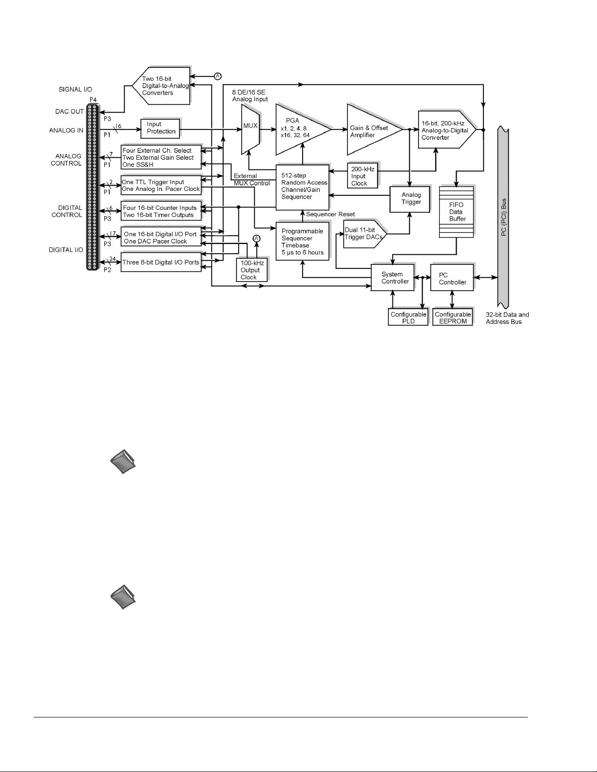
The 100-pin I/O connector, P4, is logically divided into three ports:
•
P1 – Analog input port for16 single-ended or 8 differential analog inputs with 13 software
programmable ranges (±10 V to ±156 mV full scale).
•
P2 – General purpose digital I/O port with 24 lines, or digital I/O expansion port controlling up to 192
external lines.
•
P3 – 16-bit digital I/O port, counter inputs, timer outputs, and analog outputs.
The on-board scan sequencer lets you select up to 512 channel/range combinations. The sequencer scans all
channels of the scan at 5µs or 10 µs/channel.
Bus mastering allows analog and digital/counter input data, as well as analog and digital output data, to flow
between the PC and the DaqBoard/2000 or /2000c without consuming CPU time.
DaqBoard/2000 and DaqBoard/2000c support a full complement of trigger modes including:
•
Hardware analog triggering – A user-programmed trigger level sets an analog DAC, which is
compared in hardware to the analog input level on the selected channel. Trigger latency is < 5 µs.
•
Digital and pattern triggering – The boards have separate digital trigger input line, allowing TTL-
level triggering and latencies less than 5 µs. The trigger can be programmed for logic level or edge
triggering. In pattern triggering, any of the digital input ports acts as the trigger port. You can program
the digital pattern.
•
Software-based triggering – The PC detects the trigger event from readings, either analog, digital, or
counter. Six pre- and post-triggering modes are supported.
The two 16-bit, 100-kHz analog output channels have an output from –10 V to +10 V. (These channels are
separate from the D/As used to determine analog trigger levels.) Using Bus Mastering DMA, each D/A can
output a waveform. Bus Mastering DMA also allows for digital pattern generation on the 16-bit high-speed
digital I/O port.
Other features of the DaqBoard/2000 and the DaqBoard/2000c include:
•
40 TTL-level digital I/O lines. They are divided into three 8-bit ports and one 16-bit port.
•
Four 16-bit counters. Each can accept frequency inputs up to 10 MHz. The counters can be cascaded
into two 32-bit counters.
•
Two 16-bit timer outputs. Each can generate square waves from 16 Hz to 1 MHz.
•
Configuration through software. There are no switches or jumpers on the DaqBoard/2000 or on the
DaqBoard/2000c.
DaqBoard/2000 Series & /2000c Series User’s Manual
10-18-02
Daq Systems and Device Overviews 1-9
Page 36
Connections
Installation
I/O Connectors
DaqBoard/2000 Block Diagram*
* The DaqBoard/2000c Block Diagram is the same, with exception that the /2000c board uses a
compact-PCI Bus instead of a standard PCI bus.
Reference Note: For the DaqBoard/2000 and DaqBoard/2000c installation procedure, refer to
either the DaqBoard/2000 Series Installation Guide or to the DaqBoard/2000c Series
Installation Guide, as applicable. The guides are included at the beginning of this manual.
All input and output signals are available at the board’s 100-pin P4 connector. A 3-foot, 100-conductor
ribbon cable, part number CA-195, mates with connector P4.
Reference Note: There are several P4-connector board options available for connecting the
100 pins of P4 to typical DB37 connectors (P1, P2, and P3). In addition to being briefly
discussed in chapter 2 of this manual, these options, referred to as DBK200 Series, are
detailed in the DBK Cards and Modules User’s Manual (p/n 457-0905).
1-10 Daq Systems and Device Overviews
10-18-02
DaqBoard/2000 Series & /2000c Series User’s Manual
Page 37

DaqBoard/2001 & DaqBoard/2001c
16
4
40
6
DaqBoard/2001 and DaqBoard/2001c are high-speed, multi-function, plug-and-play data acquisition boards
for PCI or compact-PCI bus computers, respectively. They feature a 16-bit, 200-kHz A/D converter, digital
calibration, bus mastering DMA, four 16-bit, 100-kHz D/A converters, 40 digital I/O lines, four counters,
and two timers.
Up to 470 channels of analog and digital I/O can be accessed with one DaqBoard/2001 or one /2001c
board. Up to four boards can be installed into a PC.
A 100-pin connector on the DaqBoard/2001 or /2001c provides access to all of the input and output signals.
The boards accommodate all I/O with one cable and one PCI [or compact-PCI] slot. The 100-pin I/O
connector, P4, is logically divided into three ports:
•
P1 – Analog input port for16 single-ended or 8 differential analog inputs with 13 software
programmable ranges (±10 V to ±156 mV full scale).
•
P2 – General purpose digital I/O port with 24 lines, or digital I/O expansion port controlling up to 192
external lines.
•
P3 – 16-bit digital I/O port, counter inputs, timer outputs, and analog outputs.
The on-board scan sequencer lets you select up to 512 channel/range combinations. The sequencer scans all
channels of the scan at 5µs or 10µs/channel.
Bus mastering allows analog and digital/counter input data, as well as analog and digital output data, to flow
between the PC and the DaqBoard/2001, or to the DaqBoard/2001c, without consuming CPU time.
DaqBoard/2001 and DaqBoard/2001c support a full complement of trigger modes including:
•
Hardware analog triggering – A user-programmed trigger level sets an analog DAC, which is
compared in hardware to the analog input level on the selected channel. Trigger latency is < 5 µs.
•
Digital and pattern triggering – The DaqBoard/2001 and /2001c have separate digital trigger input
line, allowing TTL-level triggering and latencies less than 5 µs. The trigger can be programmed for
logic level or edge triggering. In pattern triggering, any of the digital input ports acts as the trigger port.
You can program the digital pattern.
•
Software-based triggering – The PC detects the trigger event from readings, either analog, digital, or
counter. Six pre- and post-triggering modes are supported.
The four 16-bit, 100-kHz analog output channels have an output from –10 V to +10 V. (These channels are
separate from the D/As used to determine analog trigger levels.) Using Bus Mastering DMA, each D/A can
output a waveform. Bus Mastering DMA also allows for digital pattern generation on the 16-bit high-speed
digital I/O port.
Other features of the DaqBoard/2001 and /2001c include:
•
40 TTL-level digital I/O lines. They are divided into three 8-bit ports and one 16-bit port.
•
Four 16-bit counters. Each can accept frequency inputs up to 10 MHz. The counters can be cascaded
into two 32-bit counters.
•
Two 16-bit timer outputs. Each can generate square waves from 16 Hz to 1 MHz.
•
Configuration through software. There are no switches or jumpers on the DaqBoard/2001 or on the
DaqBoard/2001c.
DaqBoard/2000 Series & /2000c Series User’s Manual
10-18-02
Daq Systems and Device Overviews 1-11
Page 38

Connections
Installation
I/O Connector
DaqBoard/2001 Block Diagram*
* The DaqBoard/2001c Block Diagram is the same, with exception that the /2001c board uses a
compact-PCI Bus instead of a standard PCI bus.
Reference Note: For the DaqBoard/2001 and /2001c installation procedure, refer to either the
DaqBoard/2000 Series Installation Guide or to the DaqBoard/2000c Series Installation
Guide, as applicable. The guides are included at the beginning of this manual.
All input and output signals are available at the board’s 100-pin P4 connector. A 3-foot, 100-conductor
ribbon cable, part number CA-195, mates with connector P4.
Reference Note: There are several P4-connector board options available for connecting the
100 pins of P4 to typical DB37 connectors (P1, P2, and P3). In addition to being briefly
discussed in chapter 2 of this manual, these options, referred to as DBK200 Series, are
detailed in the DBK Cards and Modules User’s Manual (p/n 457-0905).
1-12 Daq Systems and Device Overviews
10-18-02
DaqBoard/2000 Series & /2000c Series User’s Manual
Page 39

DaqBoard/2002 & DaqBoard/2002c
40
6
DaqBoard/2002 and /2002c are high-speed, multi-function, plug-and-play data acquisition boards for PCI
and compact-PCI bus computers, respectively. They feature digital calibration, bus mastering DMA,
40 digital I/O lines, four counters, and two timers.
Up to 470 channels of analog and digital I/O can be accessed with one board. Up to four boards can be
installed into a PC.
A 100-pin connector on the boards provides access to all of the input and output signals. The boards
accommodate all I/O with one cable and one PCI [or compact-PCI] slot. The 100-pin I/O connector, P4, is
logically divided into three ports:
•
P1 – Not used by DaqBoard/2002 or DaqBoard/2002c
•
P2 – General purpose digital I/O port with 24 lines, or digital I/O expansion port controlling up to
192 external lines.
•
P3 – 16-bit digital I/O port, counter inputs, timer outputs, and analog outputs.
The on-board scan sequencer lets you select up to 512 channel/range combinations. The sequencer scans all
channels of the scan at 5 µs or 10 µs/channel.
Bus mastering allows digital/counter input data and digital output data to flow between the PC and the
DaqBoard/2002 or /2002c board without consuming CPU time.
DaqBoard/2002 and DaqBoard/2002c each supports a complement of trigger modes including:
•
Digital and pattern triggering – The boards have separate digital trigger input line, allowing TTL-
level triggering and latencies less than 5 µs. The trigger can be programmed for logic level or edge
triggering. In pattern triggering, any of the digital input ports acts as the trigger port. You can program
the digital pattern.
•
Software-based triggering – The PC detects the trigger event from readings [digital, or counter].
Six pre- and post-triggering modes are supported.
Other features of the DaqBoard/2002 and DaqBoard/2002c include:
•
40 TTL-level digital I/O lines. They are divided into three 8-bit ports and one 16-bit port.
•
Four 16-bit counters. Each can accept frequency inputs up to 10 MHz. The counters can be cascaded
into two 32-bit counters.
•
Two 16-bit timer outputs. Each can generate square waves from 16 Hz to 1 MHz.
•
Configuration through software. There are no switches or jumpers on the DaqBoard/2002 or the
DaqBoard/2002c.
DaqBoard/2000 Series & /2000c Series User’s Manual
10-18-02
Daq Systems and Device Overviews 1-13
Page 40

Connections
Installation
I/O Connector
DaqBoard/2002 Block Diagram*
*The DaqBoard/2002c Block Diagram is the same, with exception that the /2002c board uses a
compact-PCI Bus instead of a standard PCI bus.
Reference Note: For the DaqBoard/2002 and compact-PCI DaqBoard/2002c installation
procedure, refer to either the DaqBoard/2000 Series Installation Guide or to the
DaqBoard/2000c Series Installation Guide, as applicable. The guides are included at the
beginning of this manual.
All input and output signals are available at the board’s 100-pin P4 connector. A 3-foot, 100-conductor
ribbon cable, part number CA-195, mates with connector P4.
Reference Note: There are several P4-connector board options available for connecting the
100 pins of P4 to typical DB37 connectors (P1, P2, and P3). In addition to being briefly
discussed in chapter 2 of this manual, these options, referred to as DBK200 Series, are
detailed in the DBK Cards and Modules User’s Manual (p/n 457-0905).
1-14 Daq Systems and Device Overviews
10-18-02
DaqBoard/2000 Series & /2000c Series User’s Manual
Page 41
DaqBoard/2003 & DaqBoard/2003c
4
DaqBoard/2003 and /2003c are high-speed plug-and-play data acquisition boards for PCI and compact-PCI
bus computers, respectively. The boards are used for analog output and include four 16-bit, 100-kHz D/A
converters. Up to four boards can be installed into a PC.
A 100-pin connector on the boards provides access to the DAC analog output signals. The boards plug
directly into a PCI or compact-PCI bus slot, as applicable. The DAC analog output leaves the board
through “P3-designated” pins located on the board’s 100-pin P4 connector.
Both boards support Software-based triggering. In “Software-based” triggering the PC detects the trigger
event from the readings. Six pre- and post-triggering modes are supported.
DBK205
Terminations
TB1-1 AGND
TB1-2 DAC0
TB1-3 AGND
TB1-4 DAC1
TB1-5 AGND
TB1-6 DAC2
TB1-7 AGND
TB1-8 DAC3
TB1-9 AGND
TB1-10 XTTL
TB1-11 CLK
TB1-12 DGND
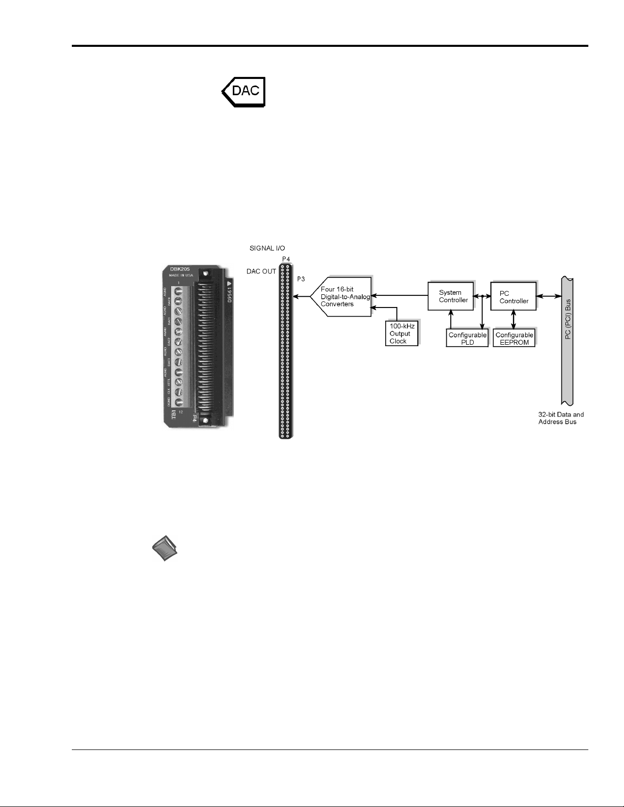
DBK205 Adapter DaqBoard/2003 Block Diagram
Connections
Installation
I/O Connector
Note
: DaqBoard/2003 and DaqBoard/2003c are shipped with one DBK205 adapter. The adapter has twelve screw
terminals as follows: DAC0, DAC1, DAC2, DAC3, 1 digital ground, 5 analog grounds, 1 external clock (CLK), and
1 external trigger (XTTL). DBK205 connects directly to DaqBoard/2003’s P4 connector.
Reference Note: For the DaqBoard/2003 and DaqBoard/2003c installation procedure, refer to
either the DaqBoard/2000 Series Installation Guide or to the DaqBoard/2000c Series
Installation Guide, as applicable. The guides are included at the beginning of this manual.
Analog output signals are available at the board’s 100-pin P4 connector. A 3-foot, 100-conductor ribbon
cable, part number CA-195, mates with connector P4; however, a DBK205 adapter board is included for
connecting the 100 pins of P4 to a terminal block (TB1).
DBK205’s TB1 includes screw terminals for: DAC0, DAC1, DAC2, and DAC3, 1 digital ground,
5 analog grounds, 1 external clock (CLK), and 1 external trigger (XTTL). DBK205 connects directly to
DaqBoard/2003’s P4 connector or compact-PCI DaqBoard/2003c’s P4 connector.
DBK205 is depicted as part of the block diagram above and is discussed briefly in chapter 2 of this manual.
DBK205 is also discussed in the DBK Cards and Modules User’s Manual (p/n 457-0905).
DaqBoard/2000 Series & /2000c Series User’s Manual
10-18-02
Daq Systems and Device Overviews 1-15
Page 42

1-16 Daq Systems and Device Overviews
10-18-02
DaqBoard/2000 Series & /2000c Series User’s Manual
Page 43

DaqBoard/2004 & DaqBoard/2004c
4
40
6
DaqBoard/2004 and /2004c are high-speed, multi-function, plug-and-play data acquisition boards for PCI
and compact-PCI bus computers, respectively. They feature bus mastering DMA, four 16-bit, 100-kHz D/A
converters, 40 digital I/O lines, four counters, and two timers.
Up to four boards can be installed in one PC.
A 100-pin connector on the boards provides access to all of the input and output signals. Each board
accommodates all I/O with one cable and one PCI [or compact-PCI] slot, as applicable. The 100-pin I/O
connector, P4, is logically divided into three ports: P1, P2, and P3; however, DaqBoard/2004 and /2004c
only make use of the P2 and P3 pin designations.
•
P1 – Not used by DaqBoard/2004 or by DaqBoard/2004c
•
P2 – General purpose digital I/O port with 24 lines, or digital I/O expansion port controlling up to 192
external lines.
•
P3 – 16-bit digital I/O port, counter inputs, timer outputs, and analog outputs.
The on-board scan sequencer lets you select up to 512 channel/range combinations. The sequencer scans all
channels of the scan at 5 µs or 10 µs per channel.
Bus mastering allows the digital/counter input data and analog and digital output data to flow between the
PC and the DaqBoard/2004 [or DaqBoard/2004c] without consuming CPU time.
DaqBoard/2004 and DaqBoard/2004c support several trigger modes, including:
•
Digital and pattern triggering – Each board has a separate digital trigger input line, allowing TTL-
level triggering and latencies less than 5 µs. The trigger can be programmed for logic level or edge
triggering. In pattern triggering, any of the digital input ports acts as the trigger port. You can program
the digital pattern.
•
Software-based triggering – The PC detects the trigger event from readings, either analog, digital, or
counter. Six pre- and post-triggering modes are supported.
The four 16-bit, 100-kHz analog output channels have an output from –10 V to +10 V. Using Bus
Mastering DMA, each D/A can output a waveform. Bus Mastering DMA also allows for digital pattern
generation on the 16-bit high-speed digital I/O port.
Other features of the DaqBoard/2004 and DaqBoard/2004c include:
•
40 TTL-level digital I/O lines. They are divided into three 8-bit ports and one 16-bit port.
•
Four 16-bit counters. Each can accept frequency inputs up to 10 MHz. The counters can be cascaded
into two 32-bit counters.
•
Two 16-bit timer outputs. Each can generate square waves from 16 Hz to 1 MHz.
•
Configuration through software. There are no switches or jumpers on the DaqBoard/2004 or on the
/2004c.
DaqBoard/2000 Series & /2000c Series User’s Manual
10-18-02
Daq Systems and Device Overviews 1-17
Page 44
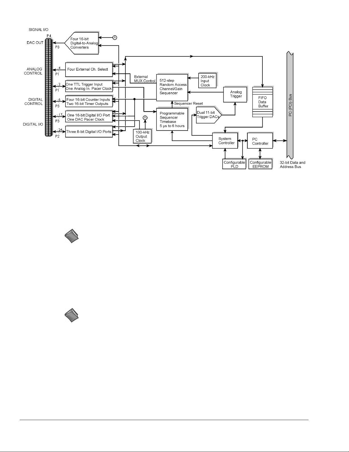
Connections
Installation
I/O Connector
DaqBoard/2004 Block Diagram*
* The DaqBoard/2004c Block Diagram is the same, with exception that the /2004c board uses a
compact-PCI Bus instead of a standard PCI bus.
Reference Note: For the DaqBoard/2004 and DaqBoard/2004c installation procedure, refer to
either the DaqBoard/2000 Series Installation Guide or to the DaqBoard/2000c Series
Installation Guide, as applicable. The guides are included at the beginning of this manual.
All input and output signals are available at the board’s 100-pin P4 connector. A 3-foot, 100-conductor
ribbon cable, part number CA-195, mates with connector P4.
Reference Note: There are several P4-connector board options available for connecting the
100 pins of P4 to typical DB37 connectors (P1, P2, and P3). In addition to being briefly
discussed in chapter 2 of this manual, these options, referred to as DBK200 Series, are
detailed in the DBK Cards and Modules User’s Manual (p/n 457-0905).
1-18 Daq Systems and Device Overviews
10-18-02
DaqBoard/2000 Series & /2000c Series User’s Manual
Page 45

DaqBoard/2005 & DaqBoard/2005c
16
40
6
DaqBoard/2005 and DaqBoard/2005c are high-speed, multi-function, plug-and-play data acquisition boards
for PCI and compact-PCI bus computers, respectively. They feature a 16-bit, 200-kHz A/D converter,
digital calibration, bus mastering DMA, 40 digital I/O lines, four counters, and two timers.
Up to 470 channels of analog and digital I/O can be accessed with one board. Up to four boards can be
installed in one PC.
A 100-pin connector on the board provides access to all of the input and output signals. The Each board
accommodates all I/O with one cable and one PCI [or compact-PCI] bus-slot, as applicable. The 100-pin
I/O connector, P4, is logically divided into three ports:
•
P1 – Analog input port for 16 single-ended or 8 differential analog inputs with 13 software
programmable ranges (±10 V to ±156 mV full scale).
•
P2 – General purpose digital I/O port with 24 lines, or digital I/O expansion port controlling up to 192
external lines.
•
P3 – 16-bit digital I/O port, counter inputs, and timer outputs.
The on-board scan sequencer lets you select up to 512 channel/range combinations. The sequencer scans
all channels of the scan at 5 µs or 10 µs per channel.
Bus mastering allows analog and digital/counter input data, as well as analog and digital output data, to flow
between the PC and the board without consuming CPU time.
DaqBoard/2005 and DaqBoard/2005c support a full complement of trigger modes, including:
•
Hardware analog triggering – A user-programmed trigger level sets an analog DAC, which is
compared in hardware to the analog input level on the selected channel. Trigger latency is < 5 µs.
•
Digital and pattern triggering – Both boards have a separate digital trigger input line, allowing TTL-
level triggering and latencies less than 5 µs. The trigger can be programmed for logic level or edge
triggering. In pattern triggering, any of the digital input ports acts as the trigger port. You can program
the digital pattern.
•
Software-based triggering – The PC detects the trigger event from readings, either analog, digital, or
counter. Six pre- and post-triggering modes are supported.
Bus Mastering DMA also allows for digital pattern generation on the 16-bit high-speed digital I/O port.
Other features of the DaqBoard/2005 and DaqBoard/2005c include:
•
40 TTL-level digital I/O lines. They are divided into three 8-bit ports and one 16-bit port.
•
Four 16-bit counters. Each can accept frequency inputs up to 10 MHz. The counters can be cascaded
into two 32-bit counters.
•
Two 16-bit timer outputs. Each can generate square waves from 16 Hz to 1 MHz.
•
Configuration through software. There are no switches or jumpers on the DaqBoard/2005 or
DaqBoard/2005c.
DaqBoard/2000 Series & /2000c Series User’s Manual
10-18-02
Daq Systems and Device Overviews 1-19
Page 46

Connections
Installation
I/O Connector
DaqBoard/2005 Block Diagram*
*The DaqBoard/2005c Block Diagram is the same, with exception that the /2005c board uses a
compact-PCI Bus instead of a standard PCI bus.
Reference Note: For the DaqBoard/2005 and compact-PCI DaqBoard/2005c installation
procedure, refer to either the DaqBoard/2000 Series Installation Guide or to the
DaqBoard/2000c Series Installation Guide, as applicable. The guides are included at the
beginning of this manual.
All input and output signals are available at the board’s 100-pin P4 connector. A 3-foot, 100-conductor
ribbon cable, part number CA-195, mates with connector P4.
Reference Note: There are several P4-connector board options available for connecting the
100 pins of P4 to typical DB37 connectors (P1, P2, and P3). In addition to being briefly
discussed in chapter 2 of this manual, these options, referred to as DBK200 Series, are
detailed in the DBK Cards and Modules User’s Manual (p/n 457-0905).
1-20 Daq Systems and Device Overviews
10-18-02
DaqBoard/2000 Series & /2000c Series User’s Manual
Page 47

Using DBK Cards and Modules for Signal Conditioning
The DBK signal-conditioning cards and module are designed for use with DaqBooks, LogBooks, and
various types of data acquisition boards, i.e., ISA, PCI, and compact-PCI types. The DBKs perform best
when used with an acquisition device that can dynamically select channel, gain, and range. DBK cards and
modules with dynamic channel and gain/range selection allow for high channel-to-channel scan rates with a
variety of transducers.
Note: Only passive DBKs, such as the DBK1 BNC module, the DBK11A screw terminal card, and the
DBK40 BNC analog interface, can be used with Daq PC-Cards.
DBK output signals can be bipolar, e.g., -5 to +5 V, or unipolar, e.g., 0 to 10 V. The user can select a range
of relevant values to correspond to the lowest signal (e.g., -5 or 0 V) and the highest signal (e.g., 5 or 10 V)
signal. This type of range selection guarantees the highest resolution in 12-bit or 16-bit conversion.
DBK modules share the same footprint as the DaqBook and a typical notebook PCs; allowing for
convenient stacking. The majority of these modules have their own power supply; however, several options
exist for packaging and powering the DBKs.
Reference Note:
DBK options are detailed in the DBK Option Cards and Modules User’s Manual
(p/n 457-0905). As a part of product support, this manual is automatically loaded onto your
hard drive during software installation. The default location is the Programs directory, which
can be accessed through the Windows Desktop.
Daq Software
The Daq devices have software options capable of handling most applications. Three types of software are
available:
Ready-to-use programs are convenient for fill-in-the-blank applications that do not require programming for
basic data acquisition and display:
•
ready-to-use graphical programs, e.g., DaqView, DaqViewXL, and post acquisition data analysis
programs such as PostView, DIAdem, and eZ-PostView
•
drivers for third-party, icon-driven software such as DASYLab and LabView
•
various language drivers to aid custom programming using API
•
DaqView is a Windows-based program for basic set-up and data acquisition. DaqView lets you
select desired channels, gains, transducer types (including thermocouples), and a host of other
parameters with a click of a PC’s mouse. DaqView lets you stream data to disk and display data
in numerical or graphical formats. PostView is a post-acquisition waveform-display program
within DaqView.
•
DaqViewXL allows you to interface directly with Microsoft Excel to enhance data handling and
display. Within Excel you have a full-featured Daq control panel and all the data display
capabilities of Excel.
•
Post acquisition data analysis programs, e.g., PostView, DIAdem, and eZ-PostView, typically
allow you to view and edit post-acquisition data.
•
The Daq Configuration control panel allows for interface configuration, testing, and
troubleshooting.
Each Daq system comes with an Application Programming Interface (API). API-language drivers include:
C/C++, Delphi, and Visual Basic. The latest software is a 32-bit version API.
DaqBoard/2000 Series & /2000c Series User’s Manual
10-18-02
Daq Systems and Device Overviews 1-21
Page 48

Reference Notes:
➣
The software document modules, DaqView, DaqViewXL, and Post Acquisition Data
Analysis User’s Guide, are not included as part of the hardcopy manual, but are
available in PDF version. See the PDF Note, below.
➣
Programming topics are covered in the Programmer’s User Manual (1008-0901). As a
part of product support, this manual is automatically loaded onto your hard drive during
software installation. The default location is the Programs directory, which can be
accessed through the Windows Desktop.
PDF
Note:
During software installation, Adobe
®
PDF versions of user manuals will automatically install
onto your hard drive as a part of product support. The default location is in the Programs
directory, which can be accessed from the Windows Desktop. Refer to the PDF
documentation for details regarding both hardware and software.
®
A copy of the Adobe Acrobat Reader
is included on your CD. The Reader provides
a means of reading and printing the PDF documents. Note that hardcopy versions of the
manuals can be ordered from the factory.
1-22 Daq Systems and Device Overviews
10-18-02
DaqBoard/2000 Series & /2000c Series User’s Manual
Page 49

Specifications
Note: Specifications are subject to change without notice.
DaqBoard/2000 Series and DaqBoard/2000c Series Boards
DaqBoard/2000 Series and DaqBoard/2000c I/O Comparison Matrix
DaqBoard/
(2000 Series)
2000 and
2000c
2001 and
2001c
2002 and
2002c
2003 and
2003c
2004 and
2004c
Analog Input
Channels
Analog Input signals enter
through P4 , go to MUX, to
PGA, to Gain & Offset
Amplifier, then to Analogto-Digital Converter (ADC)
16
16
-- --
--
--
Analog Output
Channels
Digital Signals go through
Digital-to-Analog
Converters, then through
“DAC Out” on P4.
2
4
4
4
Digital I/O
Channels
Digital signals pass
through one 16-bit
Digital I/O Port and
three 8-bit Digital I/O
Ports located on P4.
40
40
40
-- --
40
Counter/
Timers
Four 16-bit Counter
Input signals and Two
16-bit Timer Output
signals via P4 and
System Controller.
6
6
6
6
2005 and
2005c
DaqBoard/2000 Series & /2000c Series User’s Manual
16
10-18-02
--
40
Daq Systems and Device Overviews 1-23
6
Page 50

General Specifications
Applicable to all DaqBoard/2000 Series and DaqBoard/2000c Series Boards
Warm-up:
Supply voltage range:
Power consumption (per board):
Power Available for External Signal Conditioning and Expansion Options:
Operating temperature:
Storage temperature:
Relative Humidity:
Vibration:
Dimensions:
Weight:
1 hour to rated specifications
4.75 VDC to 5.25 VDC (PCI bus)
3.5 W (up to 10 W with external accessories)
5 V at 1 A (all boards); ±15 V at 75 mA each (with exception of DaqBoard/2002)
0 to +60°C
-40 to +80°C
0 to 95% non-condensing
MIL Std 810E
DaqBoard/2000 Series: 165 mm W x 15 mm D x 108 mm H (6.5” x 0.6” x 4.2”)
DaqBoard/2000c Series: 160mm W x 19 mm D x 100 mm H (6.3” x 0.7” x 3.9”)
DaqBoard/2000 Series: 160 g (0.35 lbs)
DaqBoard/2000c Series: 178.95 g (0.39 lbs)
Analog Specifications
Applicable to DaqBoard/2000, /2001, /2005, /2000c, /2001c, and /2005c
A/D:
Successive approximation, 200 kHz maximum conversion rate
Resolution:
Channels:
Conversion Time:
Connector:
Missing Codes:
16 bits
16 single-ended or 8 differential, expandable up to 256 differential
5 µs
100-pin high-density edge-type
None, over full operating temperature range
Input Voltage Ranges (software programmable via sequencer):
Voltage Range
0 to +10 V 0.015+.005 0.004+.002 1
0 to +5 V 0.015+.005 0.004+.002 1
0 to +2.5 V 0.015+.005 0.004+.002 1
0 to +1.25 V 0.015+.008 0.004+.002 2
0 to +0.625 V 0.015+.008 0.004+.002 2
0 to +0.3125 V 0.015+.008 0.004+.003 2
-10 to +10 V 0.015+.005 0.004+.001 1
-5 to +5 V 0.015+.005 0.004+.001 1
-2.5 to +2.5 V 0.015+.005 0.004+.001 1
-1.25 to +1.25 V 0.015+.005 0.004+.001 2
-0.625 to +0.625 V 0.015+.008 0.004+.001 2
-0.3125 to +0.3125 V 0.015+.008 0.004+.0015 3
-0.156 to +0.156 V 0.02+.008 0.004+.0015 3
1-24 Daq Systems and Device Overviews
Accuracy (Note 2)
One Year,
0 to 35°C
(% reading+% range)
±
Absolute Transfer
10-18-02
(Note 3)
Input Noise
(LSB rms)
10 Hz-200 kHz
(Note 4)
DaqBoard/2000 Series & /2000c Series User’s Manual
Notes
(1) Specifications assume
differential input single channel
scan, 200 kHz scan rate,
unfiltered.
(2) Accuracy specification is
exclusive of noise.
(3) Transfer accuracy assumes
calibration inside computer;
applicable for measurements
made ±5°C from ambient
temperature at calibration
(4) Inputs shorted to P4-45A,
differential input, 8192
samples.
Page 51

Voltage Specifications
(one year, 0-35°C)
Applicable to DaqBoard/2000, /2001, /2005, /2000c, /2001c, and /2005c
Differential Nonlinearity:
Integral Nonlinearity:
Temperature Coefficient:
Input Impedance:
Bias Current:
10 MΩ (single ended); 20 MΩ (differential), in parallel with 50 pF
<1 nA (0 to 35°C)
Common Mode Rejection:
≥
Hz for gains
16
Hostile Channel-to-channel Crosstalk:
Maximum Input Voltage:
Over-Voltage Protection:
±
2 LSB maximum
±
1 LSB maximum
±(10 ppm + 0.3 LSB)/°C typical
86 dB typical, from DC to 60 Hz for gains ≤8; 95 dB typical, from DC to 60
100 dB DC to 60 Hz; 86 dB @10 kHz
±11 V relative to analog common
±35 V relative to analog common
Input Sequencer
Applicable to DaqBoard/2000, /2001, /2002, /2004, /2005, /2000c, /2001c, /2004c, and /2005c
Analog, digital and counter inputs can be scanned synchronously based either on an internal
programmable timer, or an external clock source. Analog and digital outputs can also be
synchronized to either of these clocks. Bus Mastering DMA is utilized to provide CPU and systemindependent data transfers, insuring data acquisition performance irrespective of other system
activities.
Scan Clock Sources: 2
1.
Internal, programmable from 5 µs to 5.96 hours maximum in 5 µs steps
2.
External, TTL level input up to 200 kHz maximum
Programmable parameters per scan:
Depth:
512 locations
On-board Channel to channel scan rate:
Expansion channel scan rate:
5 or 10 µs per channel, programmable
channel (random order), gain, unipolar/bipolar
5 or 10 µs per channel, programmable
External Acquisition Scan Clock Input
Applicable to DaqBoard/2000, /2001, /2005, /2000c, /2001c, and /2005c
Maximum rate:
Signal Range:
Input Characteristics:
Input protection:
Trigger Level
Slew Rate Requirement
Minimum pulse width:
200 kHz
0V to +5V
100 Ω series, 20 pF to common and 10 kΩ to +5V
±8 kV ESD clamp diodes parallel
: TTL
: 14 V/µs minimum
50 ns high, 50 ns low
Triggering
Applicable to DaqBoard/2000, /2001, /2005, /2000c, /2001c, and /2005c
Trigger Sources: 6, individually selectable for starting and stopping an acquisition. Stop acquisition
can occur on a different channel than start acquisition; stop acquisition can be triggered via modes 2,
4, 5, or 6 described below. Pre-trigger is supported with fixed or variable pre-trigger periods.
Single-Channel Analog Hardware Trigger:
as the analog trigger channel, including any of the 256 analog expansion channels.
Input Signal Range:
Trigger level:
Hysteresis
Latency
Programmable (11-bit resolution), including “window triggering.”
: Programmable (11-bit resolution)
: 5 µs maximum
Anywhere within range of the selected input channel
Any analog input channel can be software programmed
DaqBoard/2000 Series & /2000c Series User’s Manual
10-18-02
Daq Systems and Device Overviews 1-25
Page 52

Single-Channel Analog Software Trigger:
Any analog input channel, including any of the 256
analog expansion channels, can be selected as the software trigger channel. If the trigger channel
involves a calculation, such as with temperature, then the driver automatically compensates for the
delay required to calculate the reading, resulting in a maximum latency of one scan period.
Input Signal Range:
Trigger level
Latency:
: Programmable (16-bit resolution), including “window triggering”
One scan period maximum
Anywhere within the range of the selected trigger channel
Single-Channel Digital Trigger:
Input Signal Range:
Trigger level
: TTL
Minimum pulse width
Latency:
5 µs maximum
-15V to +15V
: 50 ns high, 50 ns low
Digital Pattern Triggering:
A separate digital input is provided for digital triggering
8 or 16-bit pattern triggering on any of the digital input ports.
Programmable for trigger on equal, above, below, or within or outside of a window. Individual bits can
be masked for “don’t care” condition.
Latency:
Counter/Totalizer Triggering:
One scan period maximum
Counter/totalizer inputs can trigger an acquisition. User can select to
trigger on a frequency or on total counts that are equal, above, below, or within/outside of a window.
Latency:
Software Triggering:
One scan period maximum
Trigger can be initiated under program control.
Analog Output
Applicable to DaqBoard/2000, /2001, /2003, /2004, /2000c, /2001c, /2003c, and /2004c
The analog output channels are updated synchronously relative to scanned inputs, and clocked from
either an internal onboard clock, or an external clock source. Analog outputs can also be updated
asynchronously, independent of any other scanning in the system. Bus mastering DMA provides CPU
and system-independent data transfers, ensuring accurate outputs that are irrespective of other
system activities. Streaming from disk or memory is supported, allowing continuous, nearly-infinite
length, waveform outputs (limited only by available PC system resources).
Channels:
DaqBoard/2000 and DaqBoard/2000c: 2 DAC channels (DAC0, DAC1)
DaqBoard/2001, /2003, /2004, /2001c, /2003c, /2004c:
4 DAC channels each (DAC0, DAC1, DAC2, and DAC3)
Resolution:
Output voltage range:
Output current:
Offset error:
Gain error:
Update rate:
Settling Time:
Clock Sources:
1.
Onboard D/A clock, independent of scanning input clock
2.
Onboard scanning input clock
3.
External D/A input clock, independent of external scanning input clock
4.
External scanning input clock
16 bits
±10 V
±10 mA
±0.0045 V maximum
±0.01%
100 kHz maximum, 1.5 Hz minimum (no minimum with external clock)
10 µs maximum to 1 LSB for full-scale step
4
1-26 Daq Systems and Device Overviews
10-18-02
DaqBoard/2000 Series & /2000c Series User’s Manual
Page 53

Digital I/O
Applicable to DaqBoard/2000, /2001, /2002, /2004, /2005, /2000c, /2001c, /2002c, /2004c and /2005c
Channels:
Input Scanning Modes:
1.
2.
Ports:
Input Characteristics:
Input protection:
I/O levels:
Sampling/Update rate:
40, expandable to 208 with external DBK options
2
Asynchronous, under program control at any time relative to input scanning
Synchronous with input scanning
3 x 8-bit (82C55 emulation), and 1 x 16-bit. Each port is programmable as input or output.
100 Ω series, 20 pF to common
±8 kV ESD clamp diodes parallel
TTL
200 kHz maximum
Pattern Generation Output
Applicable to DaqBoard/2000, /2001, /2002, /2004, /2005, /2000c, /2001c, /2002c, /2004c, and /2005c
The P3 16-bit digital I/O port can be configured for 16-bit pattern generation. The pattern can be
updated synchronously with an acquisition from a file. If pattern generation mode is utilized, then the
D/A outputs can only be used in an asynchronous mode. Bus mastering DMA provides CPU and
system-independent data transfers, insuring data acquisition performance irrespective of other system
activities. Streaming from disk or memory is supported, allowing continuous, nearly-infinite length,
pattern outputs (limited only by available PC system resources)
Frequency/Pulse Generators
Applicable to DaqBoard/2000, /2001, /2002, /2004, /2005, /2000c, /2001c, /2002c, /2004c, /2005c
Channels:
Output Waveform:
Output rate:
High level output voltage:
Low level output voltage:
2 x 16-bit
Square wave
1 MHz base rate divided by 1 to 65535 (programmable)
2.0 V minimum @ -3.75 mA, 3.0 V minimum @ -2.5 mA
0.4 V maximum @ 2.5 mA
Frequency/Pulse Counters
Applicable to DaqBoard/2000, /2001, /2002, /2004, /2005, /2000c, /2001c, /2002c, /2004c, and /2005c
Counter inputs can be scanned synchronously along with analog and digital scanned inputs, based
either on internal programmable timer, or an external clock source. Bus mastering DMA provides
CPU and system-independent data transfers, insuring data acquisition performance irrespective of
other system activities. Counters can be configured to clear when read, or to totalize and clear under
program control.
Channels:
Input rate:
Input Signal Range:
Input Characteristics:
Input protection:
Trigger Level:
Minimum pulse width:
4 x 16-bit, cascadable as 2 x 32-bit
10 MHz maximum
-15 V to +15 V
2.7 kΩ series in parallel with 20 pF to common and 10 kΩ to +5 V
±8 kV ESD clamp diodes parallel
TTL
50 ns high, 50 ns low
Included Accessories and Software
Software:
Hardware
Windows Drivers (32-bit), 90-day Getting Started DaqView
: DBK205
is included with only DaqBoard/2003 and DaqBoard/2003c
. This adapter option
provides screw-terminal access to the board’s four analog outputs (DAC0, DAC1, DAC2,
and DAC3), 1 digital ground, 5 analog grounds, an external clock (CLK), and an external
trigger (XTTL).
DaqBoard/2000 Series & /2000c Series User’s Manual
10-18-02
Daq Systems and Device Overviews 1-27
Page 54

Optional Accessories
Software
: DaqView including drivers for DasyLab and LabView, eZ-PostView post-acquisition
software, DasyLab
Hardware
:
CA-37-x - Expansion cable. The “x” indicates number of devices on expansion side, for
example, CA-37-1 is a DB37-to-DB37 cable that provides expansion to 1 card.
CA-37 cables are used to connect from P1 to P1, P2 to P2, or P3 to P3.
CA-195 - Interconnect cable, 3-ft, 100-conductor, mates with all above options and
DaqBoard/2000 series DaqBoard/2000c series board P4 connectors.
DBK200 - Adapter panel, for connection of DBK signal conditioning and expansion options
(analog)
DBK201 - Adapter panel, connects DBK signal conditioning and expansion options
DBK202 - Adapter panel with screw terminals, connects DBK signal conditioning and
expansion options
DBK203 - Adapter module with screw terminals, connects DBK signal conditioning and
expansion options
DBK204 - Consists of a DBK203 and a CA-209 CE cable kit for meeting CE compliance
DBK205 - (included with DaqBoard/2003). This adapter option provides screw-terminal
access to DaqBoard/2003’s and DaqBoard/2003c’s four analog outputs (DAC0,
DAC1, DAC2, and DAC3) 1 digital ground, 5 analog grounds, an external clock
(CLK), and an external trigger (XTTL).
DBK206 - Screw-terminal board suitable for both analog and digital expansion. It provides
three DB37 connectors
(P1, P2, and P3) and corresponding terminal blocks.
DBK207 - Carrier board for 5B-compatible analog input modules. The DBK207 board
includes two P1 connectors for analog expansion
, a power connection terminal, and
16 signal terminal blocks.
DBK207/CJC - Carrier board for 5B-compatible analog input modules. The DBK207 board
includes two P1 connectors for analog expansion
, a power connection terminal,
16 signal terminal blocks, and cold junction sensors for cold junction compensation
(CJC) for thermocouple applications.
DBK208 - Carrier board for Opto-22 compatible solid-state-relay (SSR) digital modules.
The DBK208 board includes two P2 connectors for digital expansion, a power
connection terminal, and 16 signal terminal blocks.
DBK209 - mini-adapter board suitable for both analog and digital expansion. The board
provides three DB37 connectors (P1, P2, and P3).
DIN-DBK-1 – DIN-rail mount kit for DBK206, DBK207, and DBK208 applications.
Rack-DBK-3 – Rack mount kit for DBK206, DBK207, DBK208, and DBK209 applications.
Manuals*
Manual Set (Set #1033), Programmer, DBK, Daq2K Series, p/n 1033-0900
This is a hardcopy set of manuals that is available for purchase.
The set includes the following three manuals.
User’s Manual for DaqBoard/2000 and DaqBoard/2000c
Programmer’s Manual
(p/n 1008-0901)
DBK Option Cards & Modules User’s Manual
*PDF versions of the manuals are included on your data acquisition CD and are automatically
installed onto the host computer’s hard drive as a part of product support. The default location is the
Programs directory. The manuals can be read and printed using the Adobe Acrobat Reader ®,
which is also included on the CD.
1-28 Daq Systems and Device Overviews
.
(p/n 1033-0901)
for developing custom programs using API commands.
. (p/n 457-0905)
10-18-02
DaqBoard/2000 Series & /2000c Series User’s Manual
Page 55
DBK Basics
Introduction…… 1
How Do DBKs Connect to the Data Acquisition Device? …… 2
Connecting DBKs to DaqBooks, ISA-Type DaqBoards, and LogBooks …… 2
Connecting DBKs to Daq PC-Cards ……3
Connecting DBKs to DaqBoard/2000 Series and cPCI DaqBoard/2000c Series Boards …… 4
DBK Identification Tables ….. 5
Analog Output DBKs …… 5
Digital I/O Control DBKs …… 5
Analog Signal Conditioning DBKs …… 5
Expansion and Terminal Panel Connection DBKs …… 6
Power Supply DBKs …… 6
Tips on Setting up a Data Acquisition System …… 7
Power Supplies and Power Connectors ……8
An Introduction to Power-Related DBKs ….. 9
Calculating Your System’s Power Needs …… 11
Additional Reading ….. 13
&$87,21
Turn off power to all devices connected to the system before connecting cables or
setting configuration jumpers and switches. Electrical shock or damage to
equipment can result even under low-voltage conditions.
Introduction
The term “DBK” typically refers to a card or module that is used to expand or enhance a primary data
acquisition device, such as a DaqBook, DaqBoard, or LogBook. As will be seen in the upcoming DBK
identification tables, DBKs provide a wide variety of data acquisition functions. Depending on the DBKs
used, one or more of the following can be realized:
&$87,21
The discharge of static electricity can damage some electronic components.
Semiconductor devices are especially susceptible to ESD damage. You should
always handle components carefully, and you should never touch co nnector pins or
circuit components unless you are following ESD guidelines in an appropriate ESD
controlled area. Such guidelines include the use of properly gro unded mats and
wrist straps, ESD bags and cartons, and related procedures.
•
signal conditioning
•
analog output
•
digital I/O
•
channel expansion
•
supplying powering to another acquisition device
•
providing an interface for different connectivity; for example, in a DaqBoard/2000 Series board,
converting a P4, 100-pin connector to P1, P2, and P3 37-pin, DB37 connectors.
Daq Systems
01-28-02
DBK Basics, pg. 1
Page 56

Reference Notes: During software installation, Adobe
®
PDF versions of use r manuals will
automatically install onto your hard drive as a part of product support. The default location
is in the Programs directory, which can be accessed from the Windows Desktop. Refer to
the PDF documentation, especially the DBK Option Cards and Modules User’s Manual
(p/n 457-0905) for details regarding both hardware and software in relevant to DBKs.
A copy of the Adobe Acrobat Reader
®
is included on your CD. The Acrobat Reader
provides a means of reading and printing the PDF documents. Note that hardcopy versions
of the manuals can be ordered from the factory.
How Do DBKs Connect to the Data Acquisition Device?
Each DBK connects to the primary data acquisition device; e.g., a DaqBook, DaqBoard, or LogBook,
through one of three 37-pin ports, which are de signated as follows:
•
P1 – Analog I /O
•
P2 – Digital I/O
•
P3 – Pulse/Frequenc y/High-Speed Digital I/O
Depending on the primary data acquisition device, connectivity issues differ slightly. This will be made
clear by the figures and accompanying text that follow.
Connecting DBKs to DaqBooks, ISA-Type DaqBoards, and LogBooks
For DaqBooks, ISA-Type DaqBoards, and LogBooks, DBK connections are not made directly to the port,
but through a CA-37 -x ribbon cable, where “x” indicates the number of expansion devices that can be
connected. For example, in addition to providing a DB37 connector to interface with the primary data
acquisition device, a CA-37-3 cable includes three additional DB37 connectors. These provide a means of
adding three DBKs to one port. Use of a CA-37-16 cable will allow up to 16 DBKs to be added. The
CA-37-x cable system is excellent for DaqBooks, LogBooks, and ISA-type DaqBoards.
pg. 2, DBK Basics
Connecting DBKs to a DaqBook
The above figure applies to LogBooks, DaqBooks, and ISA-type DaqBoards. As will be seen elsewhere in
the documentation, some models do not include all three connectors (P1, P2, and P3).
02-13-02
Daq Systems
Page 57

Connecting DBKs to Daq PC-Cards
The Daq PC-Card is only intended for connections to a P1 connector of a single “passive” DBK card or
module. A passive DBK card or module is one that provides a desired connectivity (such as BNCs or screw
terminals), but performs no signal conditioning.
A CA-134 Interface Cable and a CN-86-F (dual DB37 female adapter) are used to provide the DB37,
P1 connector.
Daq PC-Card Cabling
The CA-134 cable connects to a CN-86-F adapter, which then connects to a single “passive” card or
module. The passive DBKs are:
•
DBK1 – 16 Connector BNC Module
•
DBK11A – Screw Terminal Option Card
•
DBK40 – BNC Analog Interface
Reference Note:
For information regarding the passive DBKs (DBK1, DBK11A, and DBK40), refer to the
DBK Option Cards and Modules User’s Manual (p/n 457-0905) for details regarding
both hardware and software in relevant to DBKs.
Daq Systems
02-13-02
DBK Basics, pg. 3
Page 58

Connecting DBKs to DaqBoard/2000 Series and cPCI DaqBoard/2000c Series Boards
DaqBoard/2000 Series and cPCI DaqBoard/2000 Series boards have 100-pin connectors designated as P4.
The 100 pins correlate to various pins on P1, P2, and P3 DB37 connectors.* Connectivity in the system is
as follows (see figure).
•
Both the DaqBoard/2000 and /2000c Series board connect to a CA-195 cable.
The cable has two, 100-pin, P4 connectors.
•
The CA-195 connects to a DBK200 Series adapter board or adapter module for 100-pin to
37-pin adaptations, e.g., P4-to-P1, P2, P3; but not necessarily all three.*
•
The DBK200 Series adapter connects to a CA-37-x ribbon cable, where “x” indicates the
number of expansion devices that can be connected. For example, in addition to providing a
DB37 connector to interface with the primary data acquisition device, a CA-37-3 cable
includes three additional DB37 connectors. These provide a means of adding three DBKs to
one port. Use of a CA-37-16 cable will allow up to 16 DBKs to be added.
•
The CA-37-x cable connects to expansion DBKs, in accordance with port type. For example,
Analog DBKs to port P1, Digital DBKs to port 2, and passive DBKs to port 3.
pg. 4, DBK Basics
Connecting DBKs to a DaqBoard/2000 Series Board
* DaqBoard/2003 and cPCI DaqBoard/2003c are exceptions to the above connectivity method. The /2003
board typically connects directly to a DBK205 (P4-to-Screw Terminal Adapter), as discussed in the
DBK Option Cards and Modules User’s Manual (p/n 457-0905).
02-13-02
Daq Systems
Page 59

DBK Identification Tables
Analog Output DBKs
Analog Output
Product Name/Description I/O
DBK2 V ol t age Output Card 4 channels P1
DBK5 Current Output Card 4 c hannel s P1
Digital I/O Control DBKs
Digital I/O / Control
Product Name/Description I/O
DBK20 General-Purpose Digital I/O Card (Screw Terminals) 48 channels P2
DBK21 General-Purpose Digital I/O Card (DB 37 Connectors) 48 channels P2
DBK23 Optically Isolated Digital-Input Module 24 channels P2
DBK24 Optically Isolated Digital-Output Module 24 channels P2
DBK25 Relay Output Card 8 channels P2
DBK208 Carrier board for Opto-22 Compat i bl e S o l i d-S tate-Relay
Digital Modules.
Analog Signal Conditioning DBKs
The DBKs that are used for analog signal conditioning attach to transducers and condition their outputs into
analog voltages. An A/D converter, located in the primary acquisition device, measures the analog
voltages. There are many signal-conditioning solutions available (and more are in development). Note that
DBK high-capacity modules require more circuitry than can fit on a compact card.
Two 8-bit banks of
SSR modules
Conectivity
Conectivity
Two P2s
P4
Analog Signal Conditioning
Product Name/Description I/O
DBK4 Dynamic Signal Input Card 2 channels P1
DBK7 Frequency-to-Voltage Input Card 4 channels P1
DBK8 High-Voltage Input Card 8 channels P1
DBK9 RTD Measurement Card 8 channels P1
DBK12 Low-Gain Analog Multiplexing Card
DBK13 High-Gain Analog Multiplexing Card
DBK15 Universal Current/Voltage Input Card
DBK16 Strain-Gage Measurement Card 2 channels P1
DBK17 Simultaneous Sample & Hold Card 4 channels P1
DBK18 Low-Pass Filter Card 4 channels P1
DBK19 Thermocouple Card
DBK42 5B Isolated Signal-Conditi oni ng Module 16 c hannel s P1
DBK43A Strain-Gage Measurement Module 8 channels P1
DBK44 5B Isolated Signal-Conditi oni ng Card 2 channels P1
DBK45 SSH and Low-Pass Filter Card 4 channels P1
DBK50 Isolated High-Voltage Input Module 8 channels P1
DBK51 Isolated Low-Voltage Input Module 8 channels P1
DBK52 Thermocouple Input Module
DBK53 Low-Gain Analog Multiplexing Module
DBK54 High-Gain Analog Multiplexing Module
DBK70 Vehicle Net work I nterface, Analog Multiplexer Module 16 channels P1
DBK80 Differential Voltage Input Card with Excitation Output 16 channels P1
DBK81 Thermocouple Card, High-Acc uracy 7 channels P1
DBK82 Thermocouple Card, High-Acc uracy 14 channels P1
DBK83 Thermal Couple Card, High-Accuracy; uses Connection Pod 14 channels POD-1
DBK84 Thermocouple Module, High-Accuracy 14 channels P1
DBK207 Carrier Board for 5B Compatible Analog Input Modules 16 channels Two P1s / P4
DBK207/CJC Carrier Board for 5B Compatible Analog Input Modules .
Note 1
Note 2
DBK207/CJC includes c ol d junction compensati on (CJC)
P1, P2, and P3 DB37 connect ors do not exist on the DaqBoard/2000 Series or /2000c Series boards,
:
but are obtained by using P4 adapters (DBK 200 series). These adapters typic al l y c onnect to the
DaqBoard/2000 Series [/2000c S eri es] 100-pin P4 connector via a CA-195 c abl e.
For DaqBoard/2000 and cPCI DaqBoard/2000 Series boards, internal clocks should be set to 100 kHz
:
when used with any of the following DBK options: DBK12, DBK13, DBK15, DBK 19, DBK52, DBK53,
and DBK54. See specific DBK section for detail s.
Note 2
Note 2
Note 2
Note 2
Note 2
Note 2
Note 2
16 channels P1
16 channels P1
16 channels P1
14 channels P1
14 channels P1
16 channels P1
16 channels P1
16 channels Two P1s / P4
Connectivity
1
Daq Systems
02-13-02
DBK Basics, pg. 5
Page 60

Expansion and Terminal Panel Connection DBKs
The following DBKs offer provide various expansion and connection options. The stackable 3-slot DBK10
low-profile enclosure can be used for up to three DBKs. If a system has more than 3 DBKs, the 10-slot
DBK41 can be used. Several DBK41s can be daisy-chained to accommodate many DBKs in one system.
Expansion and Connection, General
Product Name/Description I/O
DBK1 16-Connec tor BNC Adapter Module 16 connectors P1
DBK10 3-Slot Expansion Chassis 3 cards P1, P2, or P3
DBK11A Screw-Terminal Option Card (DB37-Screw Term i nal B l ock) Component
DBK40 BNC Interface 18 connectors P1 or P3
DBK41 Analog Expansion Enclosure 10 cards P1 or P2
DBK60 Expansion Chassis with Terminati on Panels 3 cards P2
Connectivity
P1
sockets
Termination Panels, Connectivity for DaqBoard/260
Product Name/Description I/O
DBK601 Termination Panel - bl ank rear panel none none
DBK602 Termination Panel - BNC rear panel 16 connectors BNC
DBK603 Termination Panel - Safety Jacks, single ended 16 connectors Safety Jacks
DBK604 Termination Panel - Safety Jacks, differential 8 differential (16) Safety Jacks
DBK605 Termination Panels - Thermal Couple, differential panel s;
specify type: B, J, K, R, S, or T
DBK606 Termination Panel – 3 Terminal Blocks; 16 connections per TB 48 connectors Screw Terminal
DBK607 Termination Panel – strain relief clamp none none
DBK608 Termination Panel – 3 female DB37 connectors three DB37 DB37
16 differential T/C Connectors
Connectivity
1
Several signal connection options were developed primarily for use with DaqBoard/2000 Series and
cPCI DaqBoard/2000c Series Boards. The DBK200 Series P4-Adapter documentation provides the basic
connection concepts. That information, along with the related DBK subsections should enable you to set up
your desired configuration.
P4 Adaptive Connection for DaqBoard/2000 Series and cPCI DaqBoard/2000c Series
Product Name/Description I/O
DBK200 P4-to-P1 Adapter Board P1 P4
DBK201 P4-to-P1/P2/P3 Adapter Board P1, P2, P3 P4
DBK202 P4-to-P1/P2/P 3 Adapter Board with Screw-Terminals P1, P2, P3 P 4
DBK203 A module version of DBK202 P1, P2, P3 P4
DBK204 A module version of DBK202 with an included CE cable kit. P1, P2, P 3 P4
DBK205 P4-to-TB1 12-slot S crew Terminal Block for DaqBoard/2003. TB1, 12-slot P4
DBK206 P4-to-P1/P2/P 3 Adapter Board with Screw-Terminals P1, P2, P3 P 4
DBK209 P4-to-P1/P2/P3 Mini-Adapter Board P1, P2, P3 P4
P1, P2, and P3 DB37 connect ors do not exist on the DaqBoard/2000 Series, or /2000c Series boards,
:
Note 1
but are obtained by using P4 adapters (DBK 200 series). These adapters typic al l y c onnect to the
DaqBoard/2000 Series [/2000c S eri es] 100-pin P4 connector via cable.
Connectivity
1
Power Supply DBKs
Power supply type DBKs are typically used in laboratory, automotive, and field applications. Input power
can come from any +10 to +20 VDC source, or from an AC source by using an appropriately rated AC-toDC adapter. The DBK30A rechargeable power supply can power DBK modules where AC mains are not
available (the DBK30A outputs 28 V for powering transducers). For a large number of DBK cards, the
DBK32A or DBK33 can be installed into an expansion slot. The DBK33 is used when +5 V is required in
addition to ±15 VDC. The DBK34 provides a steady 12 or 2 4 VDC while working with vehicle electrical
systems that may be turned on or off during testing.
Power Supply
Product Name/Description Power
DBK30A Rechargeable Battery/E xcitation Module +12-14, 24-28 V DC (3.4 A-hr @ 14 VDC)
DBK32A Auxiliary Power Supply Card ±15 V @ 500 mA
DBK33 Triple-Output Power Supply Card ±15 V @ 250 mA; +5 V @ 1 A
DBK34 Vehicle UPS Module 12/24 VDC (5 A-hr @12 VDC)
DBK34A UPS Battery Module 12/24 VDC (5 A-hr @12 VDC)
pg. 6, DBK Basics
02-13-02
Daq Systems
Page 61

Tips on Setting up a Data Acquisition System
A successful installation involves setting up equipment and setting software parameters. In addition to this
manual, you may need to consul t your Daq device or LogBook user’s manual.
DBKs should be configured before connections are made and power is applied. This sequence can prevent
equipment damage and will help ensure proper operation on startup. Many DBKs have on-board jumpers
and/or DIP switches that are used for setting channels and other variables. You will need to refer to the
individual DBK document modules to ensure that the DBKs are properly configured for you application.
Prior to designing or setting up a custom data acquisition system, you should review the following tips.
After reviewing the material you can write out the steps to setup a system that will best meet your specific
application needs.
1. The end use of the acquisition data should be used to determine how you set up and program your
acquisition system. Prior to creating the system you should understand its layout and know how you
are going to assign the channels. If you can answer the following questions you are off to a good start.
If not, you need to find the answers.
•
What engineering uni ts, ranges, sampling rates, etc. are best for your data?
•
Will the data be charted graphically, statistically processed, or exported to other programs?
•
How will the data be used?
•
How will the data be saved?
•
What are your system’ power requirements? Using several DBKs or transducers that
require excitation current may require an extra power supply, e.g., a DBK32A.
2. Assign channel numbers.
3. Plan the location of transducers, cable runs, DBKs, the acquisition device [LogBook or Daq device],
and the computer. Label your transducers, cables, and connectors to prevent later confusion.
4. When configuring your LogBook or Daq device(s) consider the following:
•
LogBook ca libration is typically performed automatically through LogView software;
however, some DBKs may require manual calibration.
•
The DaqBook and DaqBoard (ISA type) have internal jumpers and switches that you
must set manually to match your application.
•
Some DaqBook models are partially configured in software.
•
Daq PC-Cards are configured entirely in software.
•
DaqBoard/2000 Series boards are PCI type boards. They have no jumpers or switches and
are configure d entirely through software.
•
cPCI DaqBoard/2000c Series boards are compact PCI (cPCI) type boards. They have no
jumpers or switches and are configured entirely through software.
•
You may need to refer to other documentation, such as Quick Starts, Installation Guides,
User’s Manuals, and pertinent DBK document modules.
5. Perform all hardware configurations before connecting signal and power. Remember to configure all
the DBK cards and modules for your application. Several jumpers and DIP switches may need to be
set (channel, gain, filters, signal mode, etc).
6. Setting up channel p arameters often re quires both har dware and software setup.
Daq Systems
7. Route and connect all signal and power cables while all power is turned OFF.
8. To minimize electrical noise, route all signal lines away from any RF or high-voltage devices.
9. Follow your device’s specific installation instructions. For certain devices software should be installed
first; for others, hardware should be installed prior to software installation.
02-13-02
DBK Basics, pg. 7
Page 62
After software is loaded, remember to set the software parameters as needed for your
10.
application. The software must recognize all the hardware in the system. Measurement units
and ranges should be checked to verify that they meet your application requirements.
11. Remember to set all channels to the proper mode for your DBK or other signal source.
12. After your system is up and running, verify proper data acquisition and data storage.
13. Verify system accuracy; adjust ranges or calibrate as needed.
14. Device specific information regarding system setup and expansion can be found in the Daq and
LogBook User’s manuals; and in the applicable DBK document modules of this manual.
If you are considering system expansion, review the DBK10, DBK41, and DBK60 document
15.
modules. The best option depends on the number of DBK cards in your system. For just a few cards,
use the stackable 3-slot DBK10 low-profile expansion enclosure. For more than six cards, use the 10slot DBK41. DBK41s can be daisy-chained to one-another to handle a large number of DBKs.
16. In regard to power management, you should review the DBK30A, DBK32A, and DBK33 document
modules. For portable applications, the compact DBK30A rechargeable power supply can provide
power to the DBK10 or DBK41. The DBK30A also includes a 28 V output for powering 4 to 20 mA
transducers. For applications with many DBK cards (initially or in future expansion), the DBK32A or
DBK33 can be installed into any expansion slot. The DBK32A provides ±15 VDC and the DBK33
provides ±15 VDC and +5 VDC.
Power Supplies and Connectors
Power supplies convert the raw power they receive into a lower DC voltage and/or current for use by
devices with various power demands. Many of the power supplies that are used to power data acquisition
equipment are of the switching-mode type. These devices provide a regulated output whether the power
supply’s input is, for example, 60 Hz, 120 VAC as in the United States or, 50 Hz, 220 VAC as found in
European countries. Small power supplies, that do not switch, consist of simple transformer/rectifiers and
filtered capacitors; and operate over a smaller voltage range.
LogBooks - The switching-mode power supply commonly used with LogBook systems uses an input
range of 100 VAC to 240 VAC at 50 Hz to 60 Hz. The power supply’s output [to the LogBook] is
15 VDC @ 2.7 amps via a DIN5 connector.
DaqBooks - Power supplies that are used with DaqBooks are typically of the transformer/rectifier type.
They supply the DaqBook with 15 VDC @ 900 mA via a DIN5 connector.
DBKs – The following table indicates the type of power supply that is typically used with certain DBKs.
15 VDC @ 2700 mA
Switching-Mode
Type Power Supply
The DBKs in this column use up to 15 VDC @
2700 mA. This switching-mode power supply
receives power from a 100 to 240 VAC source,
at 50 to 60 Hz, and converts it to the required value.
15 VDC @ 900 mA
Transformer/Rectifier
Type, Unregulated Power Supply
The DBKs in this column use up to15 VDC @
900 mA. This transformer/rectifier type power
supply receives power from a 110 to 125 VAC
source, at 60 Hz, and converts it to the required
value.
DBK Description DBK Description
DBK32A Auxiliary Power Supply Card DBK23 Optically Isolated Digital-Input Module
DBK33 Triple-Output Power Supply Card DBK24 Optically Isolated Digital-Output Module
DBK42 5B Isolated Signal Conditioning Module DBK43A Strain Gage Measurement Module
DBK70 Vehicle Network Interface DBK50 Isolated High-Voltage Input Module
DBK51 Isolated Low-Voltage Input Module
pg. 8, DBK Basics
02-13-02
Daq Systems
Page 63

The DIN5 is the system’s basic power connector (see the following figure). The CA-115 is a 6-in. cable
D
with a plug (male) DIN5 connector on both ends. The CA-115 is used to connect DBK32As [or DBK33s]
in parallel when they are to be powered by the same power supply.
GND
Power output connector (plug)
on power supply cable and both
ends of CA-115 cable
Powe r input (or daisy-chain)
connector (socket) on device
powered (DaqBook, DBK32A,
DBK33)
DIN5 Power Connector
IN5 Power Connectors
+V
GND
+V
Power Out
Power In
Note:
Note:
DIN5 connectors for LogBook, DBK34, and DBK 34A have thread ed retaining rings.
The following figure shows the pinout for the DBK34 and DBK34A Power Out DIN5
connector. The 28 V pin is only active when the device is in the 28 VDC mode; however,
the 14 V pin is active regardless of the mode selected.
DIN5 Power Out
On a DBK34 and DBK34A
An Introduction to Power-Related DBKs
The power-related DBK options are the DBK30A, DBK32A, DBK33, DBK34, and DBK34A. From the
standpoint of providing reliable power, these DBKs have proven convenient in laboratory, automotive, and
field applications.
Input power for these devices can come from any 10 to 20 VDC source, or from an AC source via an
appropriate AC-to-DC adapter.
A brief synopsis of the DBK power options follows. Refer to the respective document modules for
complete information.
Daq Systems
02-13-02
DBK Basics, pg. 9
Page 64
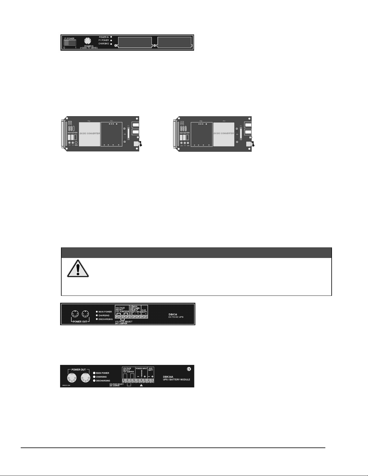
DBK30A
The DBK30A’s 28 V output will power 4 to 20 mA transducers.
module - provides power at 14 and 28 VDC with a rated capacity of 3.4 A-hr @ 14 VDC.
The module’s rechargeable power supply can power
DBK modules in situations where AC mains are not available.
: Some transducers (e.g., 2-wire 4-20 mA transmitters, bridge-configured sensors, etc) require an
Note
excitation voltage in order to work properly. The DBK30A supplies 14 and 28 VDC. Consult
transducer documentation before applying power.
DBK32A
- provides ±15 VDC @ 500 mA.
DBK33
- provides ±15 VDC @ 250 mA and +5 VDC @ 1000 mA.
The DBK32A and DBK33 power cards attach directly to the P1 analog expansion bus where they supply power
to DBK analog expansion cards. The DBK32A and the DBK33 can be powered from an included AC adapter,
an optional DBK30A battery module, or from a +10 to +20 VDC source such as a car battery.
When installed in a DBK10
three-slot expansion chassis, the DBK32A or DBK33 supplies power to
the analog DBK [that is to receive power] via a CA-37-x cable.
If used with the DBK41
ten-slot expansion enclosure, the DBK32A or DBK33 installs into one of the analog
expansion slots on the DBK41’s backplane. A power card in any DBK41slot (other than the leftmost, when
viewed from the rear) will power the other cards that are connected to the DBK41’s backplane.
&$87,21
If using a DBK32A or a DBK33 with a DaqBook or DaqBoard [ISA type], you must
entirely remove the shunt jumpers from JP1. Failure to do so will result in damage to the
8254 timer chip. Refer to the power card document modules and to the Daq device
Hardware sections of t he DaqBook and DaqBoard [ISA] user’s manuals for JP1 location
and configuration.
DBK34
Uninterruptable Power Supply (UPS) that can be used for in-vehicle testing where the vehicle’s electrical
system will not affect acquisition device power during starter-current surge, or power-off.
module – provides 12 or 24 VDC with a 5.0 or 2.5 A-hr capacity (respectively). This module is an
DBK34A
classified as a UPS / Battery module. It is an improved version of the earlier DBK34. Like the DBK34, the
DBK34A can be used for in-vehicle testing where the vehicle’s electrical system will not affect acquisition
device power during power during starter-current surge, or power-off.
pg. 10, DBK Basics
module – provides 12 or 24 VDC with a 5.0 or 2.5 A-hr capacity (respectively). This device is
02-13-02
Daq Systems
Page 65

Calculating Your System’s Power Needs
Use the chart below and the worktable on the next page to ensure your system will have sufficient power.
If the load (calculated in the worktable) exceeds available power (from the chart at the right), you must
add a power card or a module such as a DBK32A or DBK33.
Available Power Chart—Supply
Product Available Power
LogBook +5 VDC @ 0.10 A from P1-1, P2-18, P2-20, P3-20
+15 VDC @ 0.15 A from P1-21
+15 VDC @ 0.05 A from P3-19
-15 VDC @ 0.15 A from P1-2
-15 VDC @ 0.05 A from P3-37
DaqBook/100 2100 mW
DaqBook/112 2400 mW
DaqBook/120 2100 mW
DaqBook/200 4000 mW
DaqBook/216 4000 mW
DaqBook/260 4000 mW
DaqBoard/100A 3300 mW
DaqBoard/112A 3300 mW
DaqBoard/200A 3000 mW
DaqBoard/216A 3000 mW
DaqBoard/260A 3000 mW
DaqBoard/2000 Series
& /2000c Series
5000 mW; 5 V at 1 A; ±15 V at 75 mA each (with
exception of DaqBoard/2002 and /2002c)
Daq PC-Card/112B 0 mW
Daq PC-Card/216B 0 mW
DBK32 7500 mW
DBK32A 15000 mW
DBK33 7500 mW
DBK34 5 A-hr in 12 V mode; fused at 8 A
DBK34A 5 A-hr in 12 V mode; fused at 8 A
Use the following procedure and table to calculate the required system power.
1. In the Quantity column (5th), list the number of DBKs of that type in your system.
2. In the Sub Total column (7th), enter the product of column 5 and column 6 (mW).
3. Add the Sub Total column, and enter the sum at the bottom right of the table.
This result is your power requirement in mW.
DBK32, DBK32A, and DBK 34 cannot supply +5 VDC.
In cases that require +5 VDC, if the +5 VDC requirement exceeds 500 mW from a
LogBook or Daq device, then a DBK33 must be used. Note that DB K 33 can supply
1000 mW at +5 VDC.
Daq Systems
Note:
The DBK34 has an 8 amp fuse, and has a capacity of 5 A-hr when in the 12V mode,
and a capacity of 2.5 A-hr when in the 24V mode.
02-13-02
DBK Basics, pg. 11
Page 66

DBK Power Requirement Worktable—Demand
DBK Voltage Reference Calculation
Options +15 VDC -15 VDC +5 VDC Quantity × mW = Sub Total
DBK1
DBK2
DBK4
DBK5
DBK7
DBK8
DBK9
DBK11A
DBK12
DBK13
DBK15
DBK16
DBK17
DBK18
DBK19
DBK20
DBK21
DBK23***
DBK24***
DBK25
DBK40
DBK41
DBK42
DBK43A***
DBK44
DBK45
DBK50***
DBK51***
DBK52
DBK53
DBK54
DBK70***
DBK80
DBK81
DBK82
DBK83
DBK84
: DBK44’s 60 mA value is based on 30 mA for each of t wo 5B modules. This value will be higher if using
Note 1
Note 2
***
5B module 5B38 (200 mA f or each 5B38), or if using 5B39 (170 mA for each 5B39). Refer to the
DBK44 document modul e for more information.
: DBK2 and DBK5 are not used with LogBook .
Three asterisks indicate that the DBK is a module with internal power supply; powered separately.
0 0 0 0
18 mA 18 mA 5 mA 565
95 mA 80 mA 25 mA 2750
2 mA 2 mA 15 mA 135
14 mA 8 mA 18 mA 420
15 mA 15 mA <1 mA 455
21 mA 16 mA <1 mA 560
0 0 0 0
15 mA 15 mA <1 mA 455
15 mA 15 mA <1 mA 455
16 mA 16 mA <1 mA 485
37 mA 32 mA <1 mA 1040
30 mA 30 mA <1 mA 905
36 mA 36 mA <1 mA 1085
6 mA 7 mA <1 mA 200
0 0 <10 mA 50
0 0 <10 mA 50
0 0 <2 mA 10
0 0 <2 mA 10
0 0 <2 mA 10
0 0 0 0
0 0 0 0
<1 mA <1 mA <1 mA 35
<1 mA <1 mA <1 mA 35
<1 mA <1 mA 60 mA (Note 1) 330
52 mA 52 mA <1 mA 1565
<1 mA <1 mA <1 mA 35
<1 mA <1 mA <1 mA 35
6 mA 7 mA <1 mA 200
15 mA 15 mA <1 mA 455
15 mA 15 mA <1 mA 455
<1 mA <1 mA <1 mA 35
25 mA 25 mA <1 mA 755
35 mA 35 mA <2 mA 1060
60 mA 60 mA <2 mA 1810
60 mA 60 mA <2 mA 1810
60 mA 60 mA <2 mA 1810
Total Power Requirement in mW
pg. 12, DBK Basics
02-13-02
Daq Systems
Page 67

Additional Reading
During software installation, Adobe® PDF versions of user manuals will automatically install onto your hard drive
as a part of product support. The default location is in the Programs directory, which can be accessed from the
Windows Desktop. Refer to the PDF documentation for details regarding both hardware and software.
A copy of the Adobe Acrobat Reader
printing the PDF documents. Note that hardcopy versions of the manuals can be ordered from the factory.
You should refer to the following documents, as applicable, for acquisition system and programming information.
➣
DBK Option Cards and Modules User’s Manual (p/n 457-0905)
➣
DBK70 User’s Manual (p/n 1056-0901)
➣
DaqBoard [ISA] User’s Manual (p/n 457-0907)
➣
DaqBook User’s Manual (p/n 457-0906)
➣
Daq PC-Card User’s Manual (p/n 457-0908)
➣
DaqBoard/2000 Series and cPCI DaqBoard/2000c Series User’s Manual (p/n 1033-0901)
➣
LogBook User’s Manual (p/n 461-0901)
➣
Programmer’s Manual (p/n 1008-0901)
➣
Post Acquisition Data Analysis User’s Guide
Of the above listed documents, the most relevant to the DBKs is the DBK Option Cards and Modules User’s
Manual (p/n 457-0905). A synopsis of the contents follows:
®
is included on your CD. The Reader provides a means of reading and
1 – Introduction to DBKs. Explains what DBKs are and uses tables to identify the various types of
DBKs. The chapter includes tips for setting up a data acquisition system, discussions of signal
management and signal conditioning, and CE compliance information.
2 – Power Management. Explains how to determine system power requirements and discusses various
power options.
3 – System Connections and Pinouts. Provides instructions for connecting a DBK option to a Daq or
LogBook device. Pinouts are included for the P1, P2, and P3 DB37 connectors, as well as the 100pin P4 connector used by PCI and compact PCI (cPCI) boards.
4 – DBK Set Up in DaqView. Provides instruction for setting up analog and digital DBKs in
DaqView’s Hardware Configuration screen.
5 – DBK Set Up in LogView. Provides instruction for setting up analog and digital DBKs in
LogView’s Hardware Configuration window.
6 – Troubleshooting. Explains solutions to common noise, wiring, and configuration problems.
DBK Document Modules
on pages 5 and 6 of this document.
–
Includes DBK-specific documentation for the card and module options listed
Daq Systems
02-13-02
DBK Basics, pg. 13
Page 68

pg. 14, DBK Basics
02-13-02
Daq Systems
Page 69

System Connections and Pinouts 2
Overview …… 2-1
DBK200 Series, P4 Connector Options …… 2-2
Pinouts for DaqBoard/2000 Series and /2000c Series Boards …… 2-7
&$87,21
Turn off power to all devices connected to the system before connecting cables or
setting configuration jumpers and switches. Electrical shock or damage to
equipment can result even under low-voltage conditions.
&$87,21
The discharge of static electricity can damage some electronic components.
Semiconductor devices are especially susceptible to ESD damage. You should
always handle components carefully, and you should never touch co nnector pins or
circuit components unless you are following ESD guidelines in an appropriate ESD
controlled area. Such guidelines include the use of properly gro unded mats and
wrist straps, ESD bags and cartons, and related procedures.
Overview
DaqBoard/2000 Series and DaqBoard/2000c Series boards communicate [external from the host PC]
through the board’s 100-pin P4 connector. Typically, a DBK200 Series P4-adapter is used to provide one or
more DB37 connectors (P1, P2, P3), which are subsets of the 100-pin P4 connector.
Pinouts for P1, P2, P3, and P4 are located after the following DBK200 Series board descriptions.
DaqBoard/2000 Series and cPCI DaqBoard/2000c Series boards communicate [external from the host PC]
through the board’s 100-pin P4 connector. Typically a DBK200 Series P4-adapter is used to provide one or
more DB37 connectors (P1, P2, P3).
DaqBoard/2000 and DaqBoard/2000c User’s Manual
Using a DBK201 P4-to-P1/P2/P3 Adapter
03-01-02
System Connections & Pinouts 2-1
Page 70

The following matrix provides a quick comparison of the DBK200 Series adapter boards. Details for each
board are provided in the DBK Option Cards and Modules User’s Manual (p/n 457-0905). An illustration and
brief discussion of each DBK200 Series adapter board is presented after the following table.
DBK200 Series, Adapter Board Matrix
DBK P1
AnalogP2Digital
200
201
202
203
204
205
206
207
207/CJC
208
209
Yes
Yes Yes Yes Yes
Yes Yes 40-pin
No No 12
Yes Yes Yes Yes Yes
Yes
(Qty. 2)
No
Yes Yes Yes Yes
No No
No No
Yes
(Qty. 2)
P3
Pulse,
Freq.,
Digital
header
for P3
screw-
term.
No
Screw
P4
Terminals
Yes
Yes Yes Custom RC
Yes Yes
Yes Yes Can carry
Yes Yes Can carry
Special
Features
No No
No No
Filter Setup.
No
No
5B modules.
relay modules.
No No
Comments
Analog I/O use only.
Like DBK209, except for form-factor.
DBK202 is a bare board. DBK203
consists of a DBK 202 mounted in a
chassis. DBK204 consists of a DBK203
and a CA-209 CE cable kit.
Only used with DaqBoard/2003 or /2003c.
Can plug directly into P4. Screw terminals
are related to P3.
Similar to DBK202, but has a different
form-factor and has no RC f i l ter setup.
Supports 5B-compati bl e Analog I/O
modules. DBK207/CJC includes Cold
Junction Compensati on. Includes two P1
connectors. Screw terminals are for 5B
module connections.
Supports Opto-22 compati bl e Solid-StateRelay (SSR) digital modules. Includes
two P2 connectors.
Like DBK201, except for form-factor.
DBK200 Series, P4 Connector Options
Reference Note: Prior to connecting a DBK to a DaqBoard/2000 Series or /2000c Series board, refer to
the applicable DBK document module(s), in the DBK Option Cards and Modules User’s Manual
(p/n 457-0905). During software installation, the manual is automatically installed onto your hard drive as a
part of product support. The default location is the Programs directory, which can be accessed through the
Windows Desktop.
DBK200
The DBK200 P4-to-P1 adapter board provides a DB37 P1
connector.
P1 is suitable for ANALOG/IO.
DBK200 does not support Digital I/O or frequency signals.
DBK200’s P4 (100-pin connector) connects to the DaqBoard/2000
Series or DaqBoard/2000c Series board’s P4 connector via a
CA-195 Cable.
DBK200 Adapter with P1
2-2 System Connections & Pinouts
03-01-02
DaqBoard/2000 and /2000c User’s Manual
Page 71
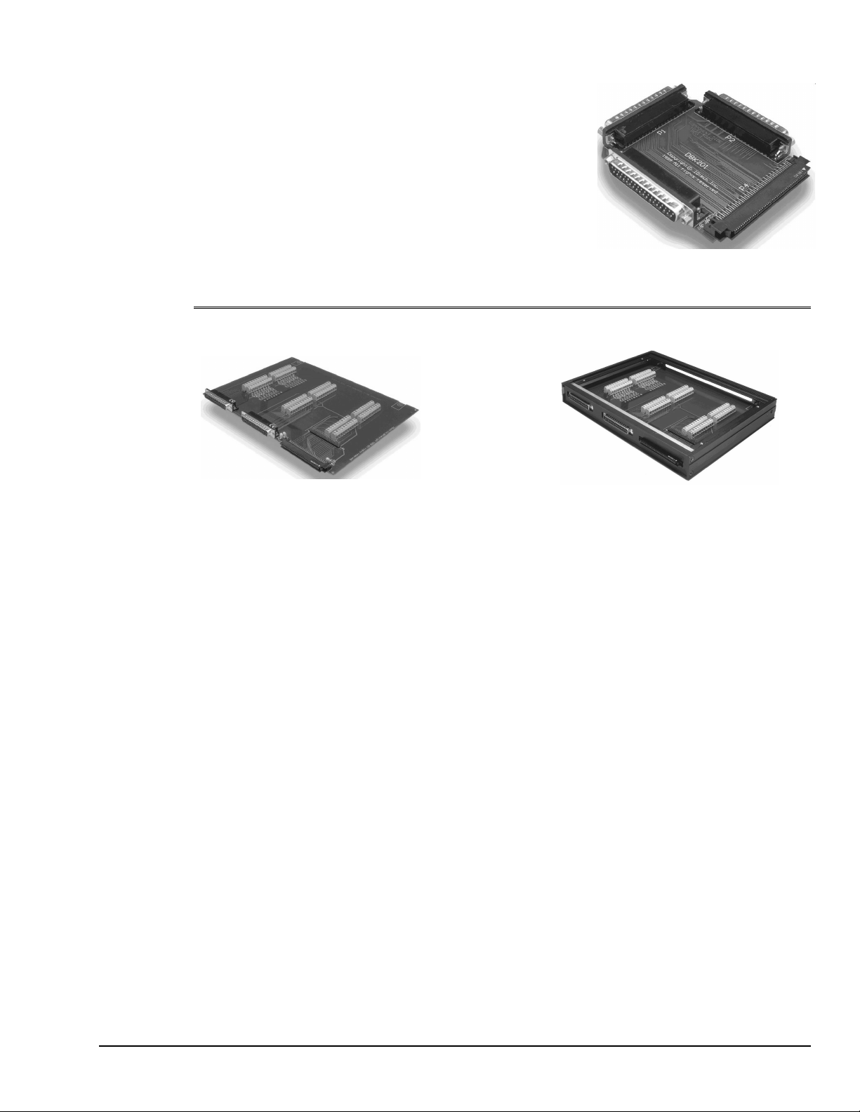
DBK201
The DBK201 P4-to-P1/P2/P3 adapter provides DB37 P1, P2, and
P3 connectors.
•
P1 is used for ANALOG I/O.
•
P2 is used for DIGITAL I/O.
•
P3 is used for Pulse/Frequency
(Digital and Counter/Timer) I/O.
DBK201’s P4 (100-pin connector) connects to a DaqBoard/2000
Series or /2000c Series board’s P4 connector via a CA-195 Cable.
DBK202, DBK203, and DBK204
DBK201, P4-to-P1/P2/P3 Adapter
DBK202
P4-to-P1/P2/P3 Adapter with Screw-Terminals
and Locators for RC Filter Setup
1
: The DBK203, DBK204, and DBK204c modules are identical. The DBK204 designation indicates
Note
DBK203, with Cover Plate Removed
Chassis-Mounted P4-to-P1/P2/P3 Adapter with
Screw-Terminals and Locators for RC Filter Setup
that the module includes a CE cable kit for use with DaqBoard/2000 Series boards that are of the
standard PCI type. The DBK204c designation indicates that the module includes a CE cable kit for
use with the compact-PCI type boards, i.e., the DaqBoard/2000c Series.
The DBK202, DBK203, DBK204, and DBK204c adapters each provide a DB37 P1 connector, DB37 P2
connector, and a 40-pin header (designated as P3).
•
P1 is used for ANALOG I/O
•
P2 for DIGITAL I/O
•
P3 for Pulse/Frequency (Digital and Counter/Timer) I/O
In addition to the P1, P2, and P3 connectors, these board s include terminal blocks designated TB1 thro ugh
TB12. The blocks provide a screw-terminal connection option for P1, P2, and P3.
Each of the three adapters can be connected to the DaqBoard/2000 Series or /2000c Series 100-pin P4
connector via a CA-195 cable.
: These screw-terminal adapter boards provides a means of connecting signals to a DaqBoard/2000
Note
Series or a /2000c Series board through one of three methods:
•
Cables connected to P1, P2, and P3 connectors, as applicable.
•
Signal wires connected t o the appropriate screw-terminal blocks (TB1 thr ough TB12).
The board’s silkscreen identifies all screw terminals.
•
With a combination of the above two methods.
1
: Board images are not to the same scale.
Note
DaqBoard/2000 and DaqBoard/2000c User’s Manual
03-01-02
System Connections & Pinouts 2-3
Page 72

DBK205
N
The DBK205 provides 12 screw-terminal connections on one terminal block (TB1) for DaqBoard/2003 and
DaqBoard/2003c. The signal lines on DBK205’s P4 connector correspond with P3-associated pins on the
P4 connector of DaqBoard/2003 and /2003c. The DBK205 can connect directly to the 100-pin P4
connector on the DaqBoard/2003, or DaqBoard/2003c.
DBK205
Terminations
TB1-1 AGND
TB1-2 DAC0
TB1-3 AGND
TB1-4 DAC1
TB1-5 AGND
TB1-6 DAC2
TB1-7 AGND
TB1-8 DAC3
TB1-9 AGND
TB1-10 XTTL
TB1-11 CLK
TB1-12 DGND
DBK205 Adapter DaqBoard/2003 Block Diagram
ote
: DBK205 connects direc tly to
DaqBoard/2003’s or /2003c’s
P4 connector.
DBK206
The DBK206 provides a P1, P2, and P3 connector and corresponding screw-terminal blocks.
•
P1 is used for ANALOG I/O
•
P2 for DIGITAL I/O
•
P3 for Pulse/Frequency (Digital and Counter/Timer) I/O
DBK206, P4-to-P1/P2/P3 Adapter with Screw-Terminals
The DBK206 is suitable for both analog and digital expansion. Signal connection to a DaqBoard/2000
Series or to a DaqBoard/2000c Series board can be made as follows:
•
With cables connected to P1, P2, and P3 connectors, as applicable.
•
With signal wires connec t ed to the appropriate scr ew-terminal blocks (TB1 through TB12).
Note that the DBK206 board’s silkscreen identifies all screw terminals.
•
With a combination of the above two methods.
Regardless of which method is used, the DBK206 connects to the 100-pin P4 connector of a
DaqBoard/2000 Series or a /2000c Series board. The connection is made via a CA-195 cable. The board
contains mounting holes that allow the board to be secured inside a user-provided enclosure.
Note: Board images are not to the same scale.
2-4 System Connections & Pinouts
03-01-02
DaqBoard/2000 and /2000c User’s Manual
Page 73

DBK207 and DBK207/CJC
The DBK207 and DBK207/CJC are carrier boards for 5B-compatible analog input modules. They
each provide:
•
two P1 connectors – for ANALOG I/O
•
a 5 VDC power terminal
•
footprints for sixteen 5B Modules
•
16 terminal blocks.
In addition, DBK207/CJC provides Cold Junction Compensation. The DBK207 and DBK207/CJC
each include a 100-pin P4 connector for use with DaqBoard/2000 Series and cPCI DaqBoard/2000c
Series Boards.
DBK207/CJC Carrier Board for 5B Compatible Modules
:$51,1*
Ensure that hard-wire emergency over-ride circuitry exists for all applications that
make use of dangerous switch-loads. Do not operate such switch-loads unless
emergency over-ride circuitry is present.
DBK207 and DBK207/CJC are typically installed in NEMA-type panels; however, they may be installed on
DIN rails. Separate mounting instructions are included with Rack Mount Kit (part no. Rack-DBK-3) and
with DIN-rail Mount Kit (part no. DIN-DBK-1).
DBK207 and DBK207/CJC allow Daq-based acquisition systems to use various combinations of sixteen
5B signal-conditioning modules. 5B modules can accommodate a variety of signals, including low-level
thermocouple and strain-gage signals. Configuration options are flexible. You can select the type of signal
attached to each channel. One Daq device can support up to 16 DBK207 [or DBK207/CJC] boards,
providing a maximum of 256 isolated, analog input channels. Note that Daq devices scan the channels at
the same 10 µs/channel rate as other DBKs (256 scans in 2.56 ms in a full system).
Each user-installed 5B module offers 500 V isolation from the system and between channels. Both
DBK207 and DBK207/CJC include 16 screw-terminal blocks for signal inputs. In addition, the
DBK207/CJC includes cold junction compensators (CJCs) for use with thermocouple 5B modules.
Sockets are provided for user-installed AC1362 current-sense resistor modules, as discussed in
5B Module Connection in the DBK207 section of the DBK Option Cards and Modules User’s Manual
(p/n 457-0905).
DaqBoard/2000 and DaqBoard/2000c User’s Manual
03-01-02
System Connections & Pinouts 2-5
Page 74

DBK208
DBK208 is a two-bank carrier board for optically-isolated Solid-State-Relay (SSR) modules. Each
bank supports up to eight digital I/O modules. The banks can be independently set as “input” or
“output” via jumpers (JP0 for Bank 0, and JP1 for Bank 1). The I/O modules are industry standard
Opto-22 compatible, 5-volt logic level modules.
The DBK208 provides:
•
two P2 connectors for DIGITAL I/O
•
footprints for sixteen optically-isolated Solid-State-Relay (SSR) Modules
•
16 dual-screw terminal blocks.
DBK208 includes a 100-pin P4 connector for use with DaqBoard/2000 Series and /2000c Series
Boards.
DBK208 Carrier Board for Opto-22 Compatible Solid-State-Relays
:$51,1*
Ensure that hard-wire emergency over-ride circuitry exists for all applications that
make use of dangerous switch-loads. Do not operate such switch-loads unless
emergency over-ride circuitry is present.
Note: DBK208 is not used with DaqBoard/2003.
DBK208 boards are typically installed in NEMA-type panels; however, they may alternatively be installed
on DIN rails. Separate mounting instructions are included with Rack Mount Kit (part no. Rack-DBK-3)
and with DIN-rail Mount Kit (part no. DIN-DBK-1).
In regard to the DaqBoard/2000 Series and DaqBoard/2000c Series boards, control originates in the board’s
100-pin P4 connector. Connection of these boards to DBK208 can be made directly or indirectly as
follows:
•
Direct connection can be made from the DaqBoard/2000 Series or /2000c Series board’s
100-pin P4 connector to a DBK208’s P4 connector via a CA-195 cable.
•
Indirect connection can be made using an additional DBK200 Series P4-adapter that includes
a 37-pin P2 connector. For example, one of the following could be used: DBK201, DBK202,
DBK203, DBK204, DBK206, DBK209, or another DBK208. CA-37 cables are used to
connect from P2 to P2.
Note that a single Daq-based data acquisition system can support up to 16 DBK208 boards, providing a
total of 256 channels. DBK208 boards contain two DB37 P2 connectors for the purpose of daisy-chaining
to other DBK208s or to other P2-supported devices.
2-6 System Connections & Pinouts
03-01-02
DaqBoard/2000 and /2000c User’s Manual
Page 75

DBK209
The DBK209 is a mini-adapter board suitable for both analog
and digital expansion. The board provides three DB37
connectors (P1, P2, and P3).
DBK209 connects to DaqBoard/2000 Series or /2000c Series
P4 connector via a CA-195 cable.
Other than the form factor, DBK209 is identical to DBK201.
•
P1 is used for ANALOG I/O.
•
P2 is used for DIGITAL I/O.
•
P3 is used for Pulse/Frequency (Digital and
Counter/Timer) I/O.
DBK209
DBK209’s P4 (100-pin connector) connects to the
DaqBoard/2000 Series or /2000c Series board’s P4
connector via a CA-195 Cable.
Pinouts for DaqBoard/2000 Series and /2000c Seri es Boar ds
Reference Notes: You must set up DaqView for the particular DBKs in your system. If you
are unfamiliar with the method of setting up DBKs in DaqView, or if you need a refresher,
refer to the following documents as needed.
➣
The DBK Set Up in DaqView chapter of the DBK Option Cards Modules User’s
Manual (p/n 457-0905),
➣
The DBK Option Cards Modules User’s Manual (p/n 457-0905), for the applicable
DBK document module(s). The documentation discusses ha rdware configuration
aspects that require setup in software.
➣
The DaqView document module.
During software installation, documentation is automatically installed onto your hard drive
as a part of product support. The default location is the Programs directory, which can be
accessed through the Windows Desktop.
P4-to-P1/P2/P3 Mini-adapter Board
Note: As new DBKs become available, be sure to use the latest revision of DaqView with the proper
configuration options.
&$87,21
Do not confuse connectors. Ensure that you only connect P1 I/Os to P1,
P2 I/Os to P2, and P3 I/Os to P3. Improper connection may result in equipment
damage.
The following P1, P2, and P3 connector pinouts pertain to the DBK200 Series adapter boards that were
discussed in the first part of this chapter. P1, P2, and P3 are subset connectors of the 100-pin P4 connector
found on the DaqBoard/2000 Series and /2000c Series boards, and for that reason P4 pin-correlation is
provided.
&$87,21
Do not confuse connectors. Ensure that you only connect P1 I/Os to P1,
P2 I/Os to P2, and P3 I/Os to P3. Improper connection may result in equipment
damage.
Note: In the pinouts that follow, some pins are irrelevant to certain DaqBoards. For example:
DaqBoard/2002, /2002c, /2004, and 2004c have no P1 correlation; and for those boards P1 and the
associated P4 pins should be ignored. The DaqBoard/2003 and /2003c only relate to P3 and the
associated P4 pins; but for these two boards, a DBK205 screw-terminal adapter is typically used
(see page 2-3). Note that chapter 1, Device Systems and Device Overviews, contains detailed
information that is specific to each board.
DaqBoard/2000 and DaqBoard/2000c User’s Manual
03-01-02
System Connections & Pinouts 2-7
Page 76
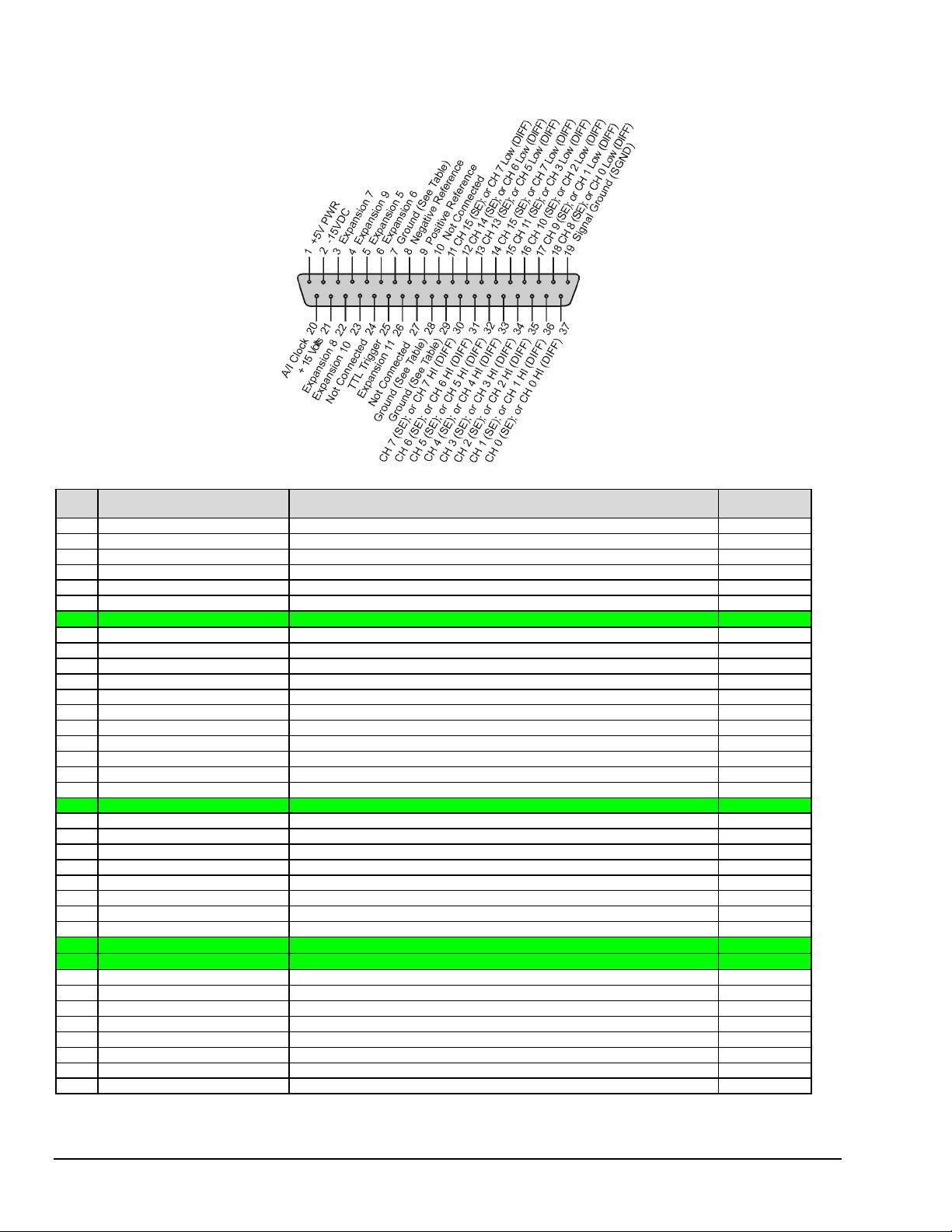
P1 for DaqBoard/2000 Series and /2000c Series Boards Analog I/O
T
d
o
P1
The P1 DB37 connector is
obtained with the use of
one of the following:
DBK200
DBK201
DBK202
DBK203
DBK204
DBK206
DBK207
DBK207/CJC
DBK209
he P1 DB37 connector
oes not apply to DBK205
r to DBK208.
Pin Signal Name Description for P1 Pin Use P4
(Refer to
1 +5 Volts Expansion +5 V power
2 -15 Volts Expansion -15 VDC power
3 Expansion 7 Digital OUT, external ADDRESS select bit 3 B32
4 Expansion 9 Digital OUT, external ADDRESS select bit 1 B33
5 Expansion 5 Digital OUT, external GAIN select bit 1 B31
6 Expansion 6 Digital OUT, external GAIN select bit 0 A32
7 Ground
8 Negative Reference Analog, -5 V reference A36
9 Positive Reference Analog +5V reference B35
10 Not Connected N/A N/A
11 CH 15 (SE), or CH 7 LO DIFF Ch 15 HI IN (singl e-ended mode) / Ch 7 LO IN (differential mode) B36
12 CH 14 (SE), or CH 6 LO DIFF Ch 14 HI IN (singl e-ended mode) / Ch 6 LO IN (differential mode) A38
13 CH 13 (SE), or CH 5 LO DIFF Ch 13 HI IN (singl e-ended mode) / Ch 5 LO IN (differential mode) B39
14 CH 12 (SE), or CH 4 LO DIFF Ch 12 HI IN (singl e-ended mode) / Ch 4 LO IN (differential mode) A41
15 CH 11 (SE), or CH 3 LO DIFF Ch 11 HI IN (singl e-ended mode) / Ch 3 LO IN (differential mode) B42
16 CH 10 (SE), or CH 2 LO DIFF Ch 10 HI IN (singl e-ended mode) / Ch 2 LO IN (differential mode) A44
17 CH 9 (SE), or CH 1 LO DIFF Ch 9 HI IN (single-ended mode) / Ch 1 LO IN (differential mode) B45
18 CH 8 (SE), or CH 0 LO DIFF Ch 8 HI IN (single-ended mode) / Ch 0 LO IN (differential mode) A47
19 Signal Ground (SGND) Sense Common (SGND) A45
20 A/I Clock External ADC Pacer Clock Input / Internal ADC Pacer Clock Output B26
21 +15 Volts Expansion +15 V power
22 Expansion 8 Digital OUT, external ADDRESS select bit 2 A33
23 Expansion 10 Digital OUT, external ADDRESS select bit 0 A34
24 Not Connected N/A N/A
25 TTL Trigger Digital IN, External TTL Trigger Input A27
26 Expansion 11 Digital OUT, Simultaneous sample and hold (SSH) B34
27 Not Connected N/A N/A
28 Ground
29 Ground
30 CH 7 (SE), or CH 7 HI DIFF Ch 7 IN (single-ended mode) / Ch 7 HI I N (differential mode) A37
31 CH 6 (SE), or CH 6 HI DIFF Ch 6 IN (single-ended mode) / Ch 6 HI I N (differential mode) B38
32 CH 5 (SE), or CH 5 HI DIFF Ch 5 IN (single-ended mode) / Ch 5 HI I N (differential mode) A40
33 CH 4 (SE), or CH 4 HI DIFF Ch 4 IN (single-ended mode) / Ch 4 HI I N (differential mode) A33, B41
34 CH 3 (SE), or CH 3 HI DIFF Ch 3 IN (single-ended mode) / Ch 3 HI I N (differential mode) A43
35 CH 2 (SE), or CH 2 HI DIFF Ch 2 IN (single-ended mode) / Ch 2 HI I N (differential mode) B44
36 CH 1 (SE), or CH 1 HI DIFF Ch 1 IN (single-ended mode) / Ch 1 HI I N (differential mode) A46
37 CH 0 (SE), or CH 0 HI DIFF Ch 0 IN (single-ended mode) / Ch 0 HI I N (differential mode) B47
Common
Common
Common
Power Management
(Refer to
Power Management
See Ground Correlation Tables, page 2-14.
(Refer to
Power Management
See Ground Correlation Tables, page 2- 14.
See Ground Correlation Tables, page 2-14.
, chapter 2, in DBK Manual)
, ch. 2, in DBK Manual)
, chapter 2, in DBK Manual)
Correlation
A1
A48
⇐
B48
⇐
⇐
2-8 System Connections & Pinouts
03-01-02
DaqBoard/2000 and /2000c User’s Manual
Page 77

P2 for DaqBoard/2000 Series and /2000c Series Boards Digital I/O
P2
The P2 DB37 connector is
obtained with the use of
one of the following:
DBK201
DBK202
DBK203
DBK204
DBK206
DBK208
DBK209
The P2 DB37 connector
does not apply to DBK200,
DBK205, DBK207, or
DBK207/CJC.
Pin Signal Name Description for P2 Pin Use P4
1 Not Connected N/A N/A
2 Not Connected N/A N/A
3 Port B - B7 Digital I/O: P2 Digital Port B, Bit 7; or, P 2 E xpansion Address Bit 0 Out B10
4 Port B - B6 Digital I/O: P2 Digital Port B, Bit 6; or, P 2 E xpansion Address Bit 1 Out A11
5 Port B - B5 Digital I/O: P2 Digital Port B, Bit 5; or, P 2 E xpansion Address Bit 2 Out B11
6 Port B - B4 Digital I/O: P2 Digital Port B, Bit 4; or, P 2 E xpansion Address Bit 3 Out A12
7 Port B - B3 Digital I/O: P2 Digital Port B, Bit 3; or, P 2 E xpansion Address Bit 4 Out B12
8 Port B - B2 Digital I/ O: P2 Digit al Port B, Bit 2; or, P2 Expansion RESET Output A13
9 Port B - B1 Digital I/O: P2 Digital Port B, Bit 1; or, P 2 E xpansion WRITE Output B13
10 Port B - B0 Digit al I/O: P2 Digital Port B , Bit 0; or, P2 Expansion READ Out put A14
11 Ground
12 Not Connected N/A N/A
13 Ground
14 Not Connected N/A N/A
15 Ground
16 Not Connected N/A N/A
17 Ground
18 + 5 Volt Supply Expansion +5 Volt Power
19 Ground
20 + 5 Volt Supply Expansion +5 Volt Power
21 Ground
22 Port C - C7 Digital I/O: P2 Digital Port C, Bit 7; or, P2 Expansion Data B i t 7 A6
23 Port C - C6 Digital I/O: P2 Digital Port C, Bit 6; or, P2 Expansion Data B i t 6 B6
24 Port C - C5 Digital I/O: P2 Digital Port C, Bit 5; or, P2 Expansion Data B i t 5 A7
25 Port C - C4 Digital I/O: P2 Digital Port C, Bit 4; or, P2 Expansion Data B i t 4 B7
26 Port C - C3 Digital I/O: P2 Digital Port C, Bit 3; or, P2 Expansion Data B i t 3 A8
27 Port C - C2 Digital I/O: P2 Digital Port C, Bit 2; or, P2 Expansion Data B i t 2 B8
28 Port C - C1 Digital I/O: P2 Digital Port C, Bit 1; or, P2 Expansion Data B i t 1 A9
29 Port C - C0 Digital I/O: P2 Digital Port C, Bit 0; or, P2 Expansion Data B i t 0 B9
30 Port A - A7 Digit al I/O: P2 Digital Port A, Bit 7; or, P2 Expansion Data Bit 15 A2
31 Port A - A6 Digit al I/O: P2 Digital Port A, Bit 6; or, P2 Expansion Data Bit 14 B2
32 Port A - A5 Digit al I/O: P2 Digital Port A, Bit 5; or, P2 Expansion Data Bit 13 A3
33 Port A - A4 Digit al I/O: P2 Digital Port A, Bit 4; or, P2 Expansion Data Bit 12 B3
34 Port A - A3 Digit al I/O: P2 Digital Port A, Bit 3; or, P2 Expansion Data Bit 11 A4
35 Port A - A2 Digit al I/O: P2 Digital Port A, Bit 2; or, P2 Expansion Data Bit 10 B4
36 Port A - A1 Digit al I/O: P2 Digital Port A, Bit 1; or, P2 Expansion Data Bit 9 A5
37 Port A - A0 Digit al I/O: P2 Digital Port A, Bit 0; or, P2 Expansion Data Bit 8 B5
Digital Common
Digital Common
Digital Common
Digital Common
Digital Common
Digital Common
See Ground Correlation Tables, page 2- 14.
See Ground Correlation Tables, page 2- 14.
See Ground Correlation Tables, page 2- 14.
See Ground Correlation Tables, page 2- 14.
(Refer to
Power Management
See Ground Correlation Tables, page 2- 14.
(Refer to
Power Management
See Ground Correlation Tables, page 2- 14.
, ch. 2, in DBK Manual)
, ch. 2, in DBK Manual)
Correlation
⇐
⇐
⇐
⇐
A1, B1
⇐
A1, B1
⇐
DaqBoard/2000 and DaqBoard/2000c User’s Manual
03-01-02
System Connections & Pinouts 2-9
Page 78

P3 for DaqBoard/2000 Series and /2000c Series Boards Pulse/Frequency/Digital I/O
D
“
(
P3
Note 2)
The P3 DB37
connector is
obtained with
the use of one
of the
following:
DBK201
DBK202
DBK203
DBK204
(Note 1)
(Note 1)
(Note 1)
DBK206
DBK209
Note: There is no direct pin number correlation between the
40-pin header and the DB37 P3 connector.
*In regard to pins 31 through 34, see Note 3.
DB37 P3 Connector
BK202, DBK203, DBK204
On-Board” 40-Pin Header
The P3 DB37 connector does not apply to DBK200, DBK205, DBK207, DBK207/CJC, or DBK208.
Pin Signal Name Description for P3 Pin Use P4
1 Digital Ground (Note 1)
2 Digital Ground (Note 1)
3 Digital 7 P3 Digital Port Bit 7 B19
4 Digital 6 P3 Digital Port Bit 6 A19
5 Digital 5 P3 Digital Port Bit 5 B20
6 Digital 4 P3 Digital Port Bit 4 A20
7 Digital 3 P3 Digital Port Bit 3 B21
8 Digital 2 P3 Digital Port Bit 2 A21
9 Digital 1 P3 Digital Port Bit 1 B22
10 Digital 0 P3 Digital Port Bit 0 A22
11 Digital Ground
12 Expansion 2 Reserved --13 Expansion 3 Reserved --14 Expansion 4 Reserved --15 Timer 0 P3 Timer 0 Output B24
16 Timer 1 P3 Timer 1 Output A25
17 Counter 2 P3 Counter 2 Input B28
18 Counter 0 P3 Counter 0 Input B29
19 + 15 Volts Expansion, +15 VDC B48
20 + 5 Volt Supply Expansion, +5 Volt Power
21 Analog Out Clock External DAC Pacer Clock Input/Internal DAC Pacer Clock Output A26
22 Digital 15 Digital I/O; P3 Digital Port Bit 15 B15
23 Digital 14 Digital I/O; P3 Digital Port Bit 14 A15
24 Digital 13 P 3 Di gi tal Port Bit 13 B16
25 Digital 12 P 3 Di gi tal Port Bit 12 A16
26 Digital 11 P 3 Di gi tal Port Bit 11 B17
27 Digital 10 P 3 Di gi tal Port Bit 10 A17
28 Digital 9 P3 Digital Port Bit 9 B18
29 Digital 8 P3 Digital Port Bit 8 A18
30 Digital Ground
31 Analog Out DAC 3 (Note 3) Analog DAC 3 Output B50
32 Analog Out DAC 2 (Note 3) Analog DAC 2 Output B49
33 Analog Out DAC 1 (Note 3) Analog DAC 1 Output A50
34 Analog Out DAC 0 (Note 3) Analog DAC 0 Output A49
35 Counter 3 P3 Counter 3 Input A28
36 Counter 1 P3 Counter 1 Input A29
37 - 15 Volts Expansion, - 15 VDC Power
Note 1: P3 pins 1 and 2 are not connect ed on DBK201.
Note 2: For DBK202, DBK203, and DBK204, the 37-pin P3 connector is obtained by connecting a CA-60 cable to an
“On-Board” 40-pin header.
Note 3: Pins 31, 32, 33, and 34 on the P3 DB37 connector are used for Analog Out DACs. DaqBoard/2001, /2003 & /2004 can
utilize all four pins. DaqBoard/2000 does not make use of pins 31 or 32. DaqBoard/2002 and DaqBoard/ 2005 boards do not
make use of pins 31 through 34 as these series two boards have no Analog Out DA C.
Digital Common
Digital Common
Digital Common
Digital Common
See Ground Correlation Tables, page 2-14.
See Ground Correlation Tables, page 2-14.
See Ground Correlation Tables, page 2-14.
(Refer to
Power Management
See Ground Correlation Tables, page 2-14.
(Refer to
Power Management
, ch. 2, in DBK Manual)
, ch. 2, in DBK Manual)
Correlation
⇐
⇐
⇐
A1, B1
⇐
A48
(Analog Out DAC 3)
(Analog Out DAC 2)
2-10 System Connections & Pinouts
03-01-02
DaqBoard/2000 and /2000c User’s Manual
Page 79

P4 to P1, P2 and P3 Correlation
The following table lists the correlation between the P4 I/O lines and their respective P1, P2 and P3 pin
locations on the DBK200 Series boards. Ground correlation is provided in a subsequent table.
P4 Pin Signal Type Description P1, P2, P3 Correlation
A1 +5VDC Power Expansion +5 Volts P1 pin 1
B1 +5VDC Power Expansion +5 Volts P1 pin 1
A2 Port A bit 7 Dig I/O P2 Digital Port A, bit 7 -orB2 Port A bit 6 Dig I/O P2 Digital Port A, bit 6 -orA3 Port A bit 5 Dig I/O P2 Digital Port A, bit 5 -orB3 Port A bit 4 Dig I/O P2 Digital Port A, bit 4 -orA4 Port A bit 3 Dig I/O P2 Digital Port A, bit 3 -orB4 Port A bit 2 Dig I/O P2 Digital Port A, bit 2 -orA5 Port A bit 1 Dig I/O P2 Digital Port A, bit 1 -orB5 Port A bit 0 Dig I/O P2 Digital Port A, bit 0 -orA6 Port C bit 7 Dig I/O P2 Digital Port C, bit 7 -orB6 Port C bit 6 Dig I/O P2 Digital Port C, bit 6 -orA7 Port C bit 5 Dig I/O P2 Digital Port C, bit 5 -orB7 Port C bit 4 Dig I/O P2 Digital Port C, bit 4 -orA8 Port C bit 3 Dig I/O P2 Digital Port C, bit 3 -orB8 Port C bit 2 Dig I/O P2 Digital Port C, bit 2 -orA9 Port C bit 1 Dig I/O P2 Digital Port C, bit 1 -orB9 Port C bit 0 Dig I/O P2 Digital Port C, bit 0 -or-
A10 Ground Dig I/O Digital Common
B10 Port B bit 7 Dig I/O P2 Digital Port B, bit 7 -orA11 Port B bit 6 Dig I/O P2 Digital Port B, bit 6 -orB11 Port B bit 5 Dig I/O P2 Digital Port B, bit 5 -orA12 Port B bit 4 Dig I/O P2 Digital Port B, bit 4 -orB12 Port B bit 3 Dig I/O P2 Digital Port B, bit 3 -orA13 Port B bit 2 Dig I/O P2 Digital Port B, bit 2 -orB13 Port B bit 1 Dig I/O P2 Digital Port B, bit 1 -orA14 Port B bit 0 Dig I/O P2 Digital Port B, bit 0 -or-
B14 Ground Dig I/O Digital Common
P2 pin 18, 20
P3 pin 20
P2 pin 18, 20
P3 pin 20
P2 pin 30
P2 expansion Data bit 15
P2 pin 31
P2 expansion Data bit 14
P2 pin 32
P2 expansion Data bit 13
P2 pin 33
P2 expansion Data bit 12
P2 pin 34
P2 expansion Data bit 11
P2 pin 35
P2 expansion Data bit 10
P2 pin 36
P2 expansion Data bit 9
P2 pin 37
P2 expansion Data bit 8
P2 pin 22
P2 expansion Data bit 7
P2 pin 23
P2 expansion Data bit 6
P2 pin 24
P2 expansion Data bit 5
P2 pin 25
P2 expansion Data bit 4
P2 pin 26
P2 expansion Data bit 3
P2 pin 27
P2 expansion Data bit 2
P2 pin 28
P2 expansion Data bit 1
P2 pin 29
P2 expansion Data bit 0
See Ground Tables
P2 pin 3
P2 expansion address bit 0
P2 pin 4
P2 expansion address bit 1
P2 pin 5
P2 expansion address bit 2
P2 pin 6
P2 expansion address bit 2
P2 pin 7
P2 expansion address bit 3
P2 pin 8
P2 expansion RESET
P2 pin 9
P2 expansion WRITE
P2 pin 10
P2 expansion READ
See Ground Tables
This table is continued.
DaqBoard/2000 and DaqBoard/2000c User’s Manual
03-01-02
System Connections & Pinouts 2-11
Page 80

P4 Pin Signal Type Description P1, P2, P3 Correlation
A15 P3 Dig bit 14 Dig I/O P3 Digital Port bit 14 P3 pin 23
B15 P3 Dig bit 15 Dig I/O P3 Digital Port bit 15 P3 pin 22
A16 P3 Dig bit 12 Dig I/O P3 Digital Port bit 12 P3 pin 25
B16 P3 Dig bit 13 Dig I/O P3 Digital Port bit 13 P3 pin 24
A17 P3 Dig bit 10 Dig I/O P3 Digital Port bit 10 P3 pin 27
B17 P3 Dig bit 11 Dig I/O P3 Digital Port bit 11 P3 pin 26
A18 P3 Dig bit 8 Dig I/O P3 Digital Port bit 8 P3 pin 29
B18 P3 Dig bit 9 Dig I/O P3 Digital Port bit 9 P3 pin 28
A19 P3 Dig bit 6 Dig I/O P3 Digital Port bit 6 P3 pin 4
B19 P3 Dig bit 7 Dig I/O P3 Digital Port bit 7 P3 pin 3
A20 P3 Dig bit 4 Dig I/O P3 Digital Port bit 4 P3 pin 6
B20 P3 Dig bit 5 Dig I/O P3 Digital Port bit 5 P3 pin 5
A21 P3 Dig bit 2 Dig I/O P3 Digital Port bit 2 P3 pin 8
B21 P3 Dig bit 3 Dig I/O P3 Digital Port bit 3 P3 pin 7
A22 P3 Dig bit 0 Dig I/O P3 Digital Port bit 0 P3 pin 10
B22 P3 Dig bit 1 Dig I/O P3 Digital Port bit 1 P3 pin 9
A23 Ground Dig I/O Digita l Common
See Ground Tables
B23 XCK Dig I/O Reserved No Connection
A24 Ground Dig I/O Digita l Common
See Ground Tables
B24 Timer 0 Dig OUT P3 Timer 0 Output P3 pin 15
A25 Timer 1 Dig OUT P3 Timer 1 Output P3 pin 16
B25 Ground Dig I/O Digita l Common
A26 DAC Pacer Dig I/O External DAC Pacer Clock Input /
See Ground Tables
P3 pin 21
Internal DAC Pacer Output
B26 ADC Pacer Dig I/O External ADC Pacer Clock I nput /
P1 pin 20
Internal ADC Pacer Output
A27 TTL Trigger Dig IN External TTL Trigger Input P1 pin 25
B27 Ground Dig I/O Digita l Common
See Ground Tables
A28 Counter 3 Di g I N P3 Counter 3 Input P3 pin 35
B28 Counter 2 Di g I N P3 Counter 2 Input P3 pin 17
A29 Counter 1 Di g I N P3 Counter 1 Input P3 pin 36
B29 Counter 0 Di g I N P3 Counter 0 Input P3 pin 18
A30 CD ACK- Dig IN Reserved No Connection
B30 SDI Di g IN Reserved No Connection
A31 Ground Analog
Analog Signal Common See Ground Tables
B31 XI/O Gain 1 Dig OUT Analog Expansion Gain Select bi t 1 P1 pin 5
A32 XI/O Gain 0 Dig OUT Analog Expansion Gain Select bi t 0 P1 pin 6
B32 XI/O Address 3 Dig OUT Analog Exp. Addres s Select bit 3 P1 pin 3
A33 XI/O Address 2 Dig OUT Analog Exp. Addres s Select bit 2 P1 pin 22
B33 XI/O Address 1 Dig OUT Analog Exp. Addres s Select bit 1 P1 pin 4
A34 XI/O Address 0 Dig OUT Analog Exp. Addres s Select bit 0 P1 pin 23
B34 External SSH Dig OUT A nal og Expansion Simultaneous
P1 pin 26
Sample/Hold Signal
A35 Ground Analog
Analog Signal Common See Ground Tables
B35 Positive Ref Analog Analog +5 Volt Referenc e P1 pin 9
A36 Negative Ref Analog Analog -5 Volt Ref erence P1 pin 8
B36 Analog In Ch15 Analog Analog Input Chan 15 (SE)
P1 pin 11
Analog Input Chan 7L (DIF)
A37 Analog In Ch7 Analog Analog Input Chan 7 (SE )
P1 pin 30
Analog Input Chan 7H (DIF)
B37 Ground Analog
A38 Analog In Ch14 Analog Analog Input Chan 14 (SE)
Analog Signal Common See Ground Tables
P1 pin 12
Analog Input Chan 6L (DIF)
B38 Analog In Ch6 Analog Analog Input Chan 6 (SE )
P1 pin 31
Analog Input Chan 6H (DIF)
A39 Ground Analog
Analog Signal Common See Ground Tables
This table is continued.
2-12 System Connections & Pinouts
03-01-02
DaqBoard/2000 and /2000c User’s Manual
Page 81
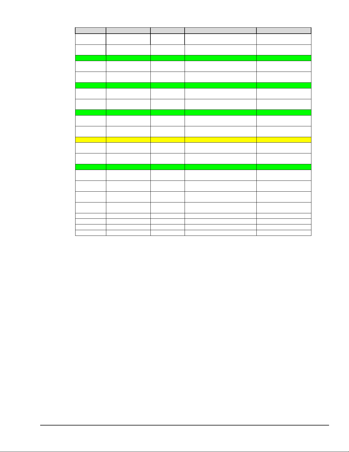
P4 Pin Signal Type Description P1, P2, P3 Correlation
B39 Analog In Ch13 Analog Analog Input Chan 13 (S E )
A40 Analog In Ch5 Analog Analog Input Chan 5 (SE)
B40 Ground Analog
A41 Analog In Ch12 Analog Analog Input Chan 12 (S E )
B41 Analog In Ch Analog Analog Input Chan 4 (SE)
A42 Ground Analog
B42 Analog In Ch11 Analog Analog Input Chan 11 (S E )
A43 Analog In Ch3 Analog Analog Input Chan 3 (SE)
B43 Ground Analog
A44 A nal og In Ch10 Analog Analog Input Chan 10 (SE)
B44 A nal og In Ch2 Analog Analog Input Chan 2 (SE)
A45 S i gnal Ground Analog Sense Common (SGND) P1-19
B45 A nal og In Ch9 Analog Analog Input Chan 9 (SE)
A46 A nal og In Ch1 Analog Analog Input Chan 1 (SE)
B46 Ground Analog
A47 A nal og In Ch8 Analog Analog Input Chan 8 (SE)
B47 A nal og In Ch0 Analog Analog Input Chan 0 (SE)
A48 -15VDC Power Expansion -15 Volt s P1 pin 2
B48 +15VDC Power Expansion +15 Volts P1 pin 21
A49 DAC 0 Analog DAC 0 Output P3 pin 34
*
B49
A50 DAC 1 Analog DAC 1 Output P3 pin 33
*
B50
DAC 2 Analog DAC 2 Output P3 pin 32
DAC 3 Analog DAC 3 Output P3 pin 31
Analog Input Chan 5L (DIF)
Analog Input Chan 5H (DIF)
Analog Signal Common See Ground Tables
Analog Input Chan 4L (DIF)
Analog Input Chan 4H (DIF)
Analog Signal Common See Ground Tables
Analog Input Chan 3L (DIF)
Analog Input Chan 3H (DIF)
Analog Signal Common See Ground Tables
Analog Input Chan 2L (DIF)
Analog Input Chan 2H (DIF)
Analog Input Chan 1L (DIF)
Analog Input Chan 1H (DIF)
Analog Signal Common See Ground Tables
Analog Input Chan 0L (DIF)
Analog Input Chan 0H (DIF)
P1 pin 13
P1 pin 32
P1 pin 14
P1 pin 33
P1 pin 15
P1 pin 34
P1 pin 16
P1 pin 35
P1 pin 17
P1 pin 36
P1 pin 18
P1 pin 37
P3 pin 37
P3 pin 19
* DAC 2 and DAC 3 (from P4 pins B49 and B50, respectively) only apply to DaqBoard/2001, /2003 /2004
and the equivalent cPCI DaqBoard/2000c Series Boards.
DaqBoard/2000 and DaqBoard/2000c User’s Manual
03-01-02
System Connections & Pinouts 2-13
Page 82

Ground Tables – P4 Pin to P1, P2, and P3 Ground Correlation
Digital Common (DGND)
P4 Pin DBK200 DBK201 DBK202
A10
B14
A23
A24
B25
B27
------- ------- ------- P1-7 ------- ------- P1-7
------- P2-11
P2-13
P2-15
P2-17
P2-19
P2-21
------- -------
------P3-11
-------
DBK203
DBK204
P2-11
P2-13
P2-15
P2-17
P2-19
P2-21
P3-1
P3-2
P3-11
P3-30
Analog Common (AGND)
P4 Pin DBK200 DBK201 DBK202
A31
A35
B37
A39
B40
A42
B43
B46
P1-7
P1-28
P1-29
------- ------- ------- ------- ------- ------- -------
------- P3-30 ------- ------- ------- ------- -------
P1-7
P1-28
P1-29
DBK203
DBK204
P1-7
P1-28
P1-29
DBK206 DBK207 DBK208 DBK209
P2-11
P2-13
P2-15
P2-17
P2-19
P2-21
P3-1
P3-2
P3-11
P3-30
DBK206 DBK207 DBK208 DBK209
------P1-28
P1-29
------- P2-11
P2-13
P2-15
P2-17
P2-19
P2-21
------- ------- P3-1
P1-7
P1-28
P1-29
------- -------
P2-11
P2-13
P2-15
P2-17
P2-19
P2-21
P3-2
P3-11
P3-30
P1-28
P1-29
P1
P2
P3
P1
P2
P3
2-14 System Connections & Pinouts
03-01-02
DaqBoard/2000 and /2000c User’s Manual
Page 83

CE-Compliance 3
Overview ……3-1
CE Standards and Directives …… 3-1
Safety Conditions ……3-2
Emissions/Immunity Conditions ……3-2
CE Enhancements for DBKs .…… 3-3
CE Cable Kits for DaqBoard 2000 Series and /2000c Series Boards…… 3-3
Overview
CE standards were developed by the European Union (EU) dating from 1985 and include specifications
both for safety and for EMI emissions and immunity. Now, all affected products sold in EU countries must
meet such standards. Although not required i n t he USA, these standards are considered good engineering
practice since they enhance safety while reducing noise and ESD problems.
In contracted and in-house testing, most Daq* products met the required specifications. Those products not
originally in compliance were redesigned accordingly. In some cases, alternate product versions, shield
plates, edge guards, special connectors, or add-on kits are required to meet CE compliance.
CE-compliant products bear the “CE” mark and include a Declaration of Conformity stating the
particular specifications and conditions that apply. The test records and supporting documentation
that validate the compliance are kept on file at the factory.
CE Standards and Directives
The electromagnetic compatibility (EMC) directives specify two basic requirements:
1. The device must not interfere with radio or telecommunications.
2. The device must be immune from electromagnetic interference from RF transmitters, etc.
The standards are published in the Official Journal of European Union under direction of CENELEC
(European Committee for Electrotechnical Standardization). The specific standards relevant to Daq*
equipment are listed on the product’s Declaration of Conformity and include: CISPR22:1985;
EN55022:1988 (Information Technology Equipment, Class A for commercial/industrial use); and
EN50082-1:1992 for various categories of EMI immunity.
The safety standard that applies to Daq* products is EN 61010-1 : 1993 (Safety Requirements for Electrical
Equipment for Measurement, Control, and Laboratory Use, Part 1: General Requirements).
Environmental conditions include the following:
•
indoor use
•
altitude up to 2000 m
•
temperature 5°C to 40°C (41°F to 104°F)
•
maximum relative humidity 80% for temperatures up to 31°C (87.8°F) decreasing linearly
to 50% relative humidity at 40°C (104°F)
•
mains supply voltage fluctuations not to exceed ±10% of the nominal voltage
•
other supply vol t age fluctuations as st ated by the manufacture r
•
transient overvoltage according to installation categories (overvoltage categories) I, II and III
For mains supply, the minimum and normal category is II
•
pollution degree I or II in accordance with IEC 664
DaqBoard/2000 Series and /2000c Series User’s Manual
07-02-01
CE-Compliance 3-1
Page 84

For clarification, terms used in some Declarations of Conformity include:
•
pollution degree: any addition of foreign matter, solid, liquid or gaseous (ionized gases) that may
produce a reduction of dielectric strength or surface resistivity. Pollution Degree I has no influence
on safety and implies: the equipment is at operating temperature with non-condensing humidity
conditions; no conductive particles are permitted in the atmosphere; warm-up time is sufficient to
avert any condensation or frost; no hazardous voltages are applied until completion of the warm-up
period. Pollution Degree II implies the expectation of occasional condensation.
•
overvoltage (installation) category: classification with limits for transient overvoltage, dependent
on the nominal line voltage to earth. Category I implies signals without high transient values.
Category II applies to typical mains power lines with some transients.
Safety Conditions
Users must comply with all relevant safety conditions in the user’s manual and the Declarations of
Conformity. This manual and Daq* hardware make use o f t he following Warning and Caution symbols:
If you see either of these symbols on a product, carefully read the related information and be alert to the
possibility of personal injury.
This warning symbol is used in this manual or on the equipment to warn of possible
injury or death from electrical shock under noted conditions.
This warning/caution symbol is used to warn of possible personal injury or equipment
damage under noted conditions.
Daq* products contain no user-serviceable parts; refer all service to qualified personnel. The specific
safety conditions for CE compliance vary by pro duct; but general safety conditions include:
•
The operator must observe all safety cautions and operating conditions specified in the
documentation for all hardware used.
•
The host computer and all connected equipment must be CE compliant.
•
All power must be off to the device and externally connected equipment before internal access to the
device is permitted.
•
Isolation voltage ratings: do not exceed documented voltage limits for power and signal inputs.
All wire insulation and terminal blocks in the system must be rated for the isolation voltage in use.
Voltages above 30 Vrms or ±60 VDC must not be applied if any condensation has formed on the
device.
•
Current and power use must not exceed specifications. Do not defeat fuses or other over-current
protection.
Emissions/Immunity Conditions
The specific immunity conditions for CE compliance vary by product; but general immunity conditions
include:
•
Cables must be shielded, braid-type with metal-shelled connectors. Input terminal connections are to
be made with shielded wire. The shield should be connected to the chassis ground with the hardware
provided.
•
The host compute r must be proper ly grounded.
•
In low-level analog applications, some inaccuracy is to be expected when I/O leads are exposed to
RF fields or transients over 3 or 10 V/m as noted on the Declaration of Conformity.
3-2 CE-Compliance
07-02-01
DaqBoard/2000 Series and /2000c Series User’s Manual
Page 85

CE Enhancements for DBKs
L
U
I
E
The following CE enhancements are described in the individual document modules of the
DBK Cards and Modules User’s Manual (p/n 457-0905).
•
DBK41/CE
•
Edge Guard (for DBK5, DBK8, and DBK44)
•
Applicable cables and connectors
CE Cable Kits for DaqBoard 2000 Series and /2000c Series Boards
&$87,21
Turn OFF the power to, and UNPLUG the host PC and externally connected equipment prior to
removing the PC’s cover and removing (or installing) the DaqBoard/2000 Series [or /2000c Series]
Board. Electric shock or damage to equipment can result even under low-voltage conditions.
Take ESD precautions (packaging, proper handling, grounded wrist strap, etc.)
Use care to avoid touching board surfaces and onboard components. Only handle boards by their
edges (or ORBs, if applicable). Ensure boards do not come into contact with foreign elements such
as oils, water, and industrial particula t e.
Note: The CE Cable Kit used with DaqBoard/2000 Series Boards is p/n CA-209.
The CE Cable Kit used with cPCI DaqBoard/2000c Series Boards is p/n CA-209c.
By following these instructions correctly, your DaqBoard/2000 Series [or /2000c Series] Board will be
CE Compliant in accordance with the conditions stated on your board’s Declaration of Conformity.
If your board is already installed, you will need to remove it from the PC before proceeding. If your board
is not yet installed, proceed to the section entitled, Install the CE ORB.
Remove DaqBoard/2000 Series or /2000c Series Board from the Host PC
For DaqBoard/2000 Series Boards [PCI type]
1. Turn the host PC’s power OFF.
2. Turn power OFF to externally connected equipment.
3. UNPLUG the host PC and all externally connected equipment.
4. Remove the PC’s cover. Refer to your PC Owner’s Manual as needed.
5. Locate the DaqBoard/2000 Series Board and carefully remove the board from its PCI slot.
For cPCI DaqBoard/2000c Series Boards [cPCI Type]
1. Turn the compact PC’s power OFF.
2. Turn power OFF to externally connected
equipment.
3. UNPLUG the compact PC and all
externally connected equipment.
4. Loosen the upper and lower lock screws
(see figure).
5. Push the cPCI board’s injector/ejector
down to disengage the board.
6. Slide the board free of the compact PC.
njector/
jector
ower Lock Screw
pper Lock Screw
Removing a cPCI DaqBoard/2000c Series Board
DaqBoard/2000 Series and /2000c Series User’s Manual
07-02-01
CE-Compliance 3-3
Page 86

Install the CE ORB
1. Remove the two screws that secure the standard [non-CE] ORB to the board (see figures).
2. Using the same screws, mount the CE ORB to the board. Tighten the screws snug, but do not over
tighten.
Note: For the cPCI DaqBoard/2000c Series Boards, the board’s edge will locate between the
Mounting DaqBoard/2000 Series and cPCI DaqBoard/2000c Series Boards to CE ORBs
ORB’s Retaining Edge and the two screw mounts.
Install the Board with its CE ORB
For DaqBoard/2000 Series Boards [PCI type]
If you a installing the DaqBoard/2000 Series Board for the first time, refer to chapter 1 of this manual;
or to the DaqBoard/2000 Series Quick Start Guide, prior to installing the board.
1. If you have not already done so, turn off power to, and
UNPLUG the host PC and externally connected
equipment. Then remove the PC’s cover. Refer to your
PC Owner’s Manual as needed.
2. Install the DaqBoard/2000 Series Board[with CE ORB]
as follows:
(a) Align the groove in the edge connector with the
ridge on the PCI slot.
(b) Push the DaqBoard/2000 Series Board firmly
into the PCI slot.
(c) Replace the rear panel adapter screw.
3. Replace the PC’s cover.
Installing a DaqBoard/2000 Series Board
3-4 CE-Compliance
07-02-01
DaqBoard/2000 Series and /2000c Series User’s Manual
Page 87

For cPCI DaqBoard/2000c Series Boards [cPCI Type]
L
U
I
E
If you a installing the cPCI DaqBoard/2000c Series Board for the first time, refer to chapter 2 of this
manual; or to the cPCI DaqBoard/2000c Series Quick Start Guide, prior to installing the board.
1. Turn the compact PC’s power OFF.
2. Turn power OFF to externally connected
equipment.
UNPLUG the compact PC and all
3.
externally connected equipment.
4. With the board’s injector/ejector down,
slide the board into the compact PC.
Make sure you use the P Cs card guides.
5. After the board is inserted, pull the cPCI
board’s injector/ejector up to engage t he
board.
6. Tighten the upper and lower lock screws.
Connect the CA-195CE Cable to the Board
Note: This section includes illustrations depicting the DaqBoard/2000; but apply to both the
DaqBoard/2000 Series Boards and the cPCI DaqBoard/2000c Series Boards.
pper Lock Screw
njector/
jector
ower Lock Screw
Installing a cPCI DaqBoard/2000c Series Board
Note: When mating P4 connectors, ensure that the P4 white locator triangles
point to each other. The triangles locate pin A1.
1. Connect one end of the CA-195CE Cable to DaqBoard/2000 Series [or /2000c Series] Board’s P4
connector. Note that either end of the cable can be connected to the board; however, the white locator
triangles must align with each other.
2. Align the Cable Clamp (1033-2009) with the
CE ORB and secure the items with two
4-40 x 3/16 screws (provided).
Note: In the right hand figure, the cable is not shown to
allow for greater clarity of parts.
DaqBoard/2000 Series and /2000c Series User’s Manual
07-02-01
CE-Compliance 3-5
Page 88

Secure the Grounding Pigtail to Cable CA-195CE
Using Cable Clamps 1033-2009, 1033-2010, and two 4_40 x 5/16 screws, secure the Grounding Pigtail to
the cable. Note that the Clamps must be positioned over the cable’s Copper Band as shown in the figure on
page 3-5. Tighten screws snug, but do not over tighte n.
Note: In the following figure, the cable is not shown to allow for greater clarity of parts.
Connect Cable and Grounding Pigtail to DBK203
Note: DBK204 [for use with DaqBoard/2000 Series Boards] consists of a DBK203 and a CA-209 CE
cable kit. DBK204c [for use with cPCI DaqBoard/2000c Series Boards] consists of a DBK203 and
a CA-209c CE cable kit.
1. Verify correct P4 connector alignment of the CA-195CE Cable and DBK203’s P4 connector.
2. Complete the connection.
3. Connect the open end of the Grounding Pigtail to the threaded insert located to the right of
DBK203’s P4 connector. See figure on page 3-5.
Note: When mating P4 connectors, ensure that the P4 white locator triangles
point to each other. The triangles locate pin A1.
At this point your board will be CE compliant, providing that the conditions listed on your board’s
Declaration of Conformity are satisfied. You can return power to the system and commence with normal
operation of your DaqBoard/2000 Series [or /2000c Series] Board.
3-6 CE-Compliance
07-02-01
DaqBoard/2000 Series and /2000c Series User’s Manual
Page 89

Calibration 4
DaqBoard/2000 Series boards and compact PCI DaqBoard/2000c series boards are factory-calibrated.
If adjustments are needed, they should be completed in the following order:
1. PGA Input and Output Offset
2. Sample/Hold Offset
3. A/D Offset and Gain
4. VDC Voltage Reference
5. DAC0 Full-Scale*
6. DAC1 Full-Scale*
7. DAC2 Full-Scale*
8. DAC3 Full-Scale*
*In regard to the six types of DaqBoard/2000 Series and /2000c Series boards, DAC applicability is as
follows:
DaqBoard/2000 and /2000c– DAC0 and DAC1 apply
DaqBoard/2001 and /2001c– DAC0, DAC1, DAC2, and DAC3 apply
DaqBoard/2002 and /2002c– No DACs apply
DaqBoard/2003 and /2003c– DAC0, DAC1, DAC2, and DAC3 apply
DaqBoard/2004 and /2004c– DAC0, DAC1, DAC2, and DAC3 apply
DaqBoard/2005 and /2005c – No DACs apply
A Windows-based program, DaqCal.exe, is used to calibrate Daq systems, including analog expansion
cards. DaqCal.exe is used in conjunction with:
•
a 4.5-digit, digital multi-meter
•
an adjustable voltage calibrator
•
an ambient temperature meter.
To use the calibration program:
1. Launch DaqCal.
Note: DaqCal is installed automatically from your data acquisition CD as a part of product
support. This takes place during software installation. DaqCal’s default location is the
IOtech DaqX Software folder, in the Programs directory.
2. When DaqCal opens you will be prompted to select your device from a list. After doing so,
simply follow the illustrated on-screen instructions.
DaqBoard/2000 Series & /2000c User’s Manual
10-18-02
Calibration 4-1
Page 90

4-2 Calibration
10-18-02
DaqBoard/2000 Series & /2000c Series User’s Manual
Page 91

Glossary
Acquisition
Analog
Analog-to-Digital
Converter (ADC)
API
Bipolar
Buffer
A collection of scans acquired at a specified rate as controlled by the sequencer.
A signal of varying voltage or current that communicates data.
A circuit or device that converts analog values into digital values, such as binary bits, for use in
digital computer processing.
Application Program Interface. The interface program within the Daq* system’s driver that
includes function calls specific to Daq* hardware and can be used with user-written programs
(several language s supported).
A range of analog signals with positive and negative values (e.g., -5 to +5 V); see unipolar.
Buffer refers to a ci rcuit or device that allows a signal to pass through it, while p roviding
isolation, or another function, without altering the signal. Buffer usually refers to:
(a)
A device or circuit that allows for the temporary storage of data during data transfers. Such
storage can compensate for differences in data flow rates. In a FIFO (First In - First Out)
buffer, the data that is stored first is also the first data to leave the buffer.
(b)
A follower stage used to drive a number of gates without overloading the preceding stage.
(c)
An amplifier which accepts high source impedance input and results in low source
impedance output (effectively, an impedance buffer).
Buffer Amplifier
Channel
Common mode
Common mode
voltage
Crosstalk
Digital
An amplifier used primarily to match two different impedance points, and isolate one stage from
a succeeding stage in order to prevent an undesirable interaction between the two stages. (Also
see, Buffer).
In reference to Daq*, channel simply refers to a single input, or output entity.
In a broader sense, an input channel is a signal path between the transducer at the point of
measurement and the data acquisition system. A channel ca n go through various stages
(buffers, multiplexers, or signal conditioning amplifiers and filters). Input channels are
periodically sampled for readings.
An output channel from a device can be digital or analog. Outputs can vary in a programmed
way in response to an input channel signal.
Common mode pertains to signals that are identical in amplitude and duration; also can be used
in reference to signal components.
Common mode voltage refers to a volt age magnitude (refe renced to a common point) that is
shared by 2 or more signals. Example: referenced to common, Signal 1 is +5 VDC and Signal
2 is +6 VDC. The common mode voltage for the two signals is +5.5 VDC [(5 + 6)/2].
An undesired transfer of signals between systems or system components. Crosstalk causes signal
interference, more commonly referred to as noise.
A digital signal is one of discrete value, in contrast to a varying signal. Combinations of binary
digits (0s and 1s) represent digital data.
DaqBoard/2000 Series & /2000c S eri es User’s Manual
09-13-00
Glossary G-1
Page 92

Digital-to-Analog
Converter (DAC)
A circuit or device that converts digital values (binary bits), into analog signals.
DIP switch
Differential mode
Differential mode
voltage
ESD
Excitation
A DIP switch is a group of miniature switches in a small Dual In-line Package (DIP). Typically,
users set these switches to configure their particular application.
The differential mode measures a voltage between 2 signal lines for a single channel. (Also see
single-ended mode).
Differential mode voltage refers to a voltage difference between two signals that are referenced to
a common point. Example: Signal 1 is +5 VDC referenced to common. Signal 2 is +6 VDC
referenced to common.
If the +5 VDC signal is used as the reference, the differential mode voltage is +1 VDC
(+ 6 VDC - +5 VDC = +1 VDC).
If the +6 VDC signal is used as the reference, the differential mode voltage is -1 VDC
(+ 5 VDC - +6 VDC = -1 VDC).
Electrostatic discharge (ESD) is the transfer of an electrostatic charge between bodies having
different electrostatic potentials. This transfer occurs during direct contact of the bodies, or
when induced by an electrostatic field. ESD energy can damage an integrated circuit (IC); so
safe handling is required.
Some transducers [e.g. strain gages, thermistors, and resistance temperature detectors (RTDs)]
require a known voltage or current. Typically, the variation of thi s signal through the
transducer corresponds to the condition measured.
Gain
Isolation
Linearization
Multiplexer (MUX)
Sample (reading)
Scan
Sequencer
Simultaneous
Sample-and-Hold
The degree to which an input signal is amplified (or attenuated) to allow greater accuracy and
resolution; can be expressed as ×n or ±dB.
The arrangement or operation of a circuit so that signals from another circuit or device do not
affect the isolated circuit.
In reference to Daq*, isolation usually refers to a separation of the direct link between the signal
source and the analog-to-digital converter (ADC). Isolation is necessary when measuring high
common-mode voltage.
Some transducers produce a voltage in linear proportion to the condition measured. Other
transducers (e.g., thermocouples) have a nonlinear response. To convert nonlinear signals into
accurate readings requires software to calibrate several points in the range used and then
interpolate values between these points.
A device that collects signals from several inputs and outputs them on a single channel.
The value of a signal on a channel at an instant in time. When triggered, the ADC reads the
channel and converts the sampled value into a 12- or 16-bit value.
The channels that are selected for sampling.
A programmable device that manages channels and channel-specific settings.
An operation that gathers samples from multiple channels at the same instant and holds these
values until all are sequentially converted to digital values.
Single-ended mode
The single-ended mode measures a voltage between a signal line and a common reference that
may be shared with other channels. (Also see differential mode).
G-2 Glossary
09-13-00
DaqBoard/2000 Series & /2000c S eri es User’s Manual
Page 93

Trigger
An event to start a scan or mark an instant during an acquisition. The event can be defined in
various ways; e.g., a TTL signal, a specified voltage level in a monitored channel, a button
manually or mechanically engaged, a software command, etc. Some applications may use preand post-triggers to gather data around an instant or based on signal counts.
TTL
Unipolar
Transistor-Transistor Logic (TTL) is a circuit in which a multiple-emitter transistor has replaced
the multiple diode cluster (of the diode-transistor logic circuit); typically used to communicate
logic signals at 5 V.
A range of analog signals that is always zero or positive (e.g., 0 to 10 V). Evaluating a signal in
the right range ( uni polar or bipolar) a l lows greater resolution by using the full-range of the
corresponding digital value. See bipolar.
DaqBoard/2000 Series & /2000c S eri es User’s Manual
09-13-00
Glossary G-3
Page 94

G-4 Glossary
09-13-00
DaqBoard/2000 Series & /2000c S eri es User’s Manual
 Loading...