

Page 1
PB-600
Instruction Manual
Page 2

PB-600 Instruction Manual
Index
0.Product description.................................................................................
1.Notes on operation
2.Front and back panel
3.Derating curve
3.1 Charging current VS temperature
3.2 Charging current VS input voltage
4.Function description for CN100
5.LED Indication
6.Explanation of operation logic (charging stages)
6.1 2 stage charging (flick switch to "2" stage)
6.2 3 stage charging (flick switch to "3" stage)
6.3 8 stage charging (flick switch to "8" stage)
7.Function description
7.1 Input voltage
7.2 PFC
7.3 Remote control
7.4 2, 3, or 8 stage charging mode selection
7.5 Reverse polarity protection
7.6 Fan speed control
7.7 Charger OK relay (RY15)
7.8 Output OK relay (RY13)
7.9 Temperature compensation
8.Wir ing for bat ter y
9.Suggested battery capacity
10.Series and parallel connection of batteries
11.Recommend ed wire spe cification
12.Failure correction notes
.................................................................................................
.................................................................................
..............................................................................
........................................................................................
......................................................
.....................................................
...............................................................
........................................................................................
......................................
.........................................
.........................................
.........................................
...............................................................................
....................................................................................
.................................................................................
...........................................
...............................................................
.............................................................................
..................................................................
....................................................................
..............................................................
...................................................................................
.....................................................................
............................................
.......................................................
........................................................................
1
1
1
2
2
2
2
3
3
3
4
5
6
6
6
6
7
7
7
7
8
8
8
9
9
9
10
Sep. 2014 Version 11
Page 3
0.Produc t desc rip tion
PB-600 is MW's next generation smart charger. It has many of the protective features
that con s u m e rs woul d l i k e t o h ave in a cha r g e r i nclud i n g b a ttery mis c o n nectio n
(wrong voltage), reverse polarity, battery disconnection or not connected, and battery
fa ilure analy sis. The lat est hi g h eff iciency swi tchin g topo logy pl us microcon trol l er
po we r m a n a g e m e nt are utilized in its de s i g n . T hree types of cha rg i n g c u r v e s a r e
off ered for lead acid ba ttery charging, 2 stages for q uick chargin g, 3 stages (quick +
float ), an d 8 stag es fo r optimiz ed ch argi ng. Charg ing s tage sele ction can be easily
ma de by t he us er thr ough the selec tion switch on the fro nt pa nel.
Depending on battery brand and type (lead acid, gel, lithium iron, and lithium manganese);
th e b a t tery may re q u i re special c h a rging curv e s a n d adjustmen t t o the protec t i v e
functions which differs from the standard settings. The charging curves and protective
functions can be customized by reprogramming its firmware. Basically, you can change
the voltage/current settings of each individual stage plus adjust or cancel the protective
functions. Please not e, the fac tory chargi ng cu rve i s for c harging lead-acid battery.
Please contact MW reg ardi ng ot her types o f bat tery c har ging r equ irements.
1.Notes on operation:
◎Desig ned f or cha rgi ng lea d aci d battery.
◎Must be installed in a dry and well ventilated a rea. It should no t be exposed to rain
or snow.
◎Th e c a b l es between ch a r g er and battery sh o u l d be kept as shor t a s p ossible to
prevent excessive voltage drop. Too much voltage drop will lead to longer charging
perio d.
◎Pl e a s e m ake sure char g i n g v oltage and cu r r e nt meets batt e r y s p ecificati o n .
◎Ref r a i n from conne ct i n g n ew and old batt e r i e s in series.
◎Char g e r s hould be in the O F F m o de before mak i n g b attery connec t io n or disconne ct i on .
◎Thre e y e a r s warr a n ty is pro v i d e d unde r n o r mal op e r a ting c o n d i tio n s . F ailur e
re s u l t ing from impr o p e r o peration wi l l r e s ult in cancel l a t io n of warran t y.
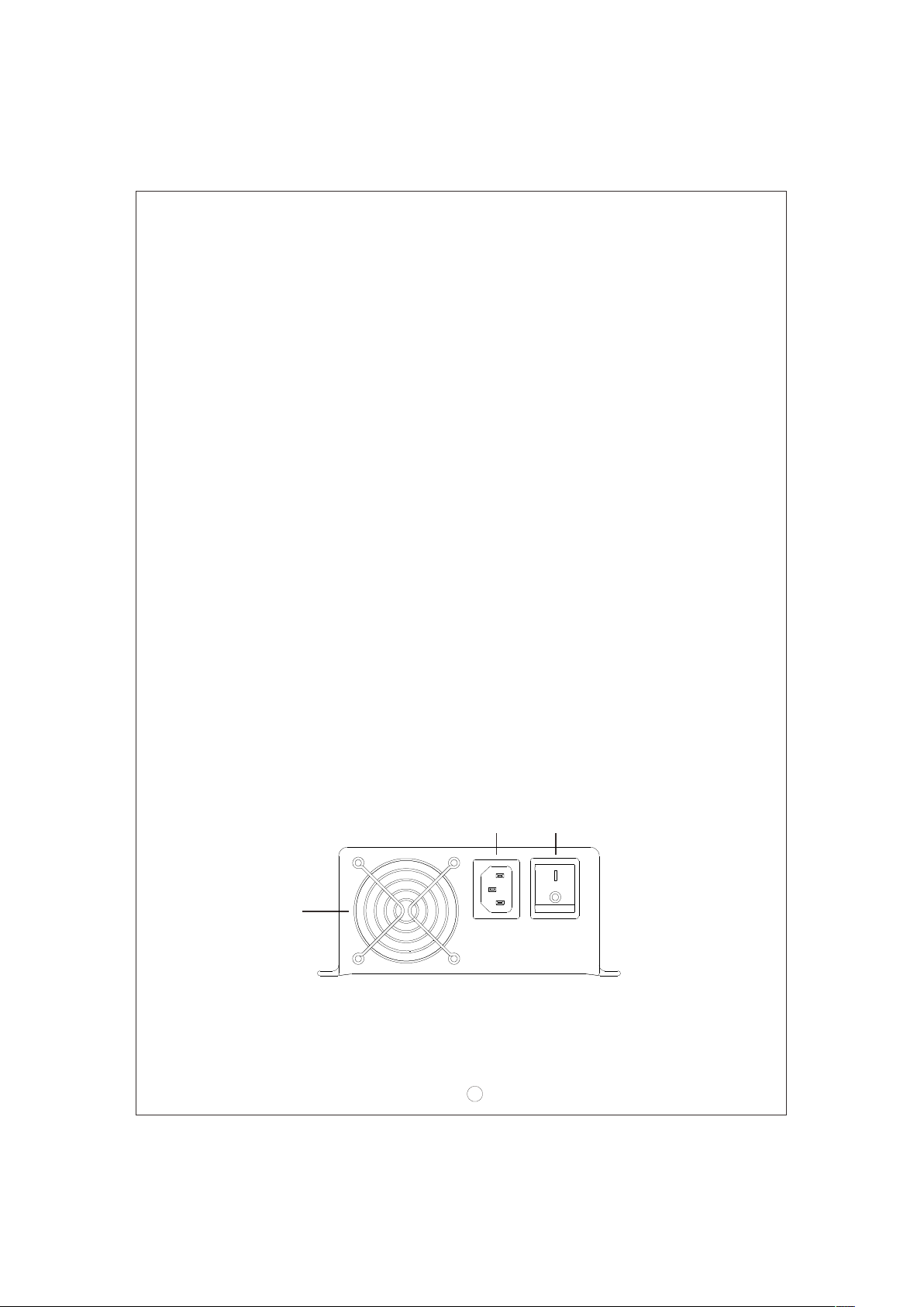
2.Front and back panel
Fan
Ventila t io n
Hole
AC INL ET ON/O FF SWIT C H
ON
OFF
AC IN PUT
Figu re 2. 1 Fro nt Panel
1
Page 4
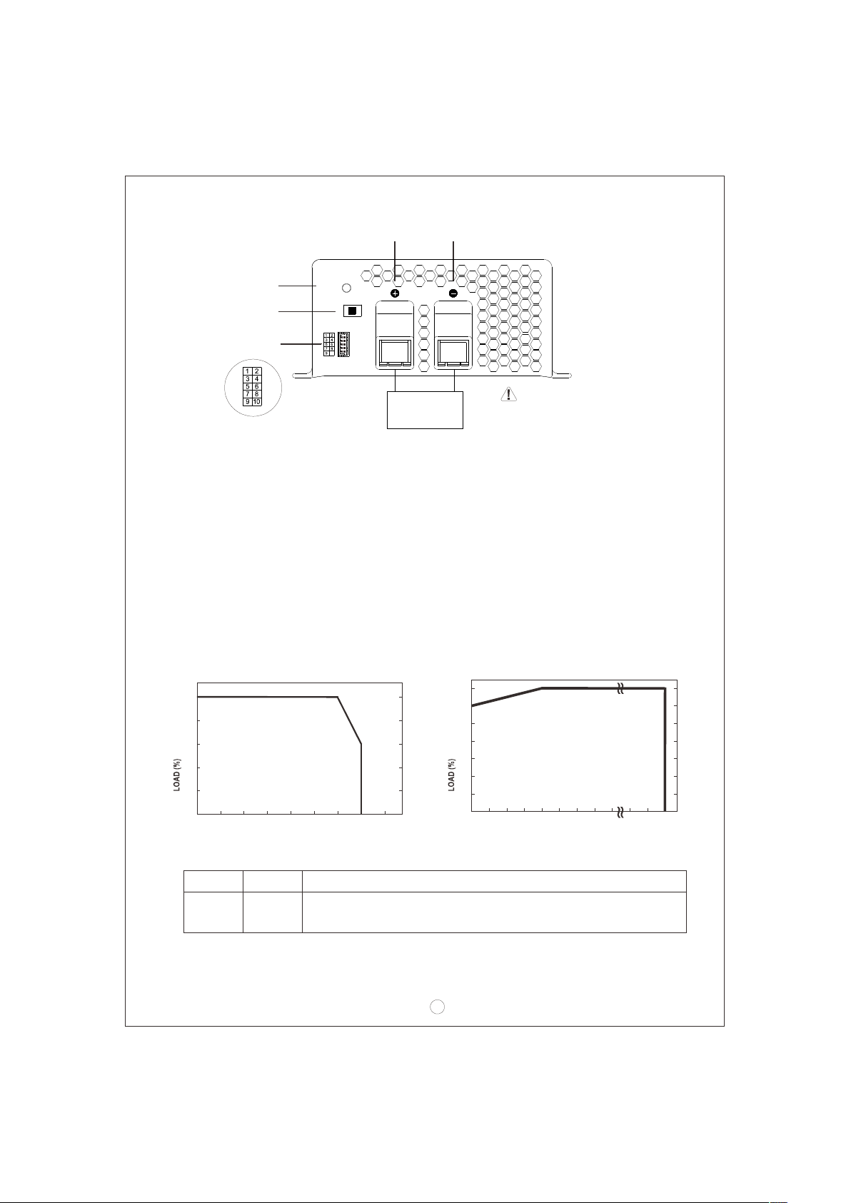
Battery
Positive
Common
Negative
LED
Indi cat or
Power
Stage 8/3/2
2/3/ 8 sta ge
sele cti on swit ch
Functi on
Connector
10
+
Battery
-
WARNING :
Please ch eck batt ery
pola rit y bef ore
Figu re 2. 2 Back Panel
co nnection
Assem bly guidelin es:
1.The cha rger sho uld b e tur ned O FF prior to battery connecti on. Suitable wire gauge
should be chosen bas ed on rated charging current of the charger unit. Double-check
battery polarity before making the battery connection. Positive terminal of the charger
mu st be co n nect ed to + of t he batt ery an d n egat ive te r mina l to of the b atte ry. Also ,
ma k e sure the p o sitiv e a n d negat i ve termi n als of the c harger a r e not acci d entall y
short ed togeth er.
2. Af t e r p l u g gi n g in the AC p o w e r c able, flick t h e O N / O F F ( 0/-) switc h to t h e O N ( - )
posit ion. The LED in dica tor o n the switc h will l igh t up.
3.Derating curve
3.1 Charging cu rrent VS tem perature 3.2 Charging cu rrent VS inp ut voltage
100
80
60
40
20
100
90
80
70
60
50
40
-20 0 10 20 30 40 50 60 70
AMBIENT TEMPER ATURE ( )℃
4.Function description for CN10 0
Pin No. Function
1,2 RY13
Description
Rela y co ntact rat ing (max. ): 30V/ 1A. "Shor t" when battery is ful l.
"Open" w he n bat te ry is still c hargi ng.
(HO RIZON TAL)
2
90 95 100
INPUT VOLTAGE (VAC) 60Hz
115 264
Page 5
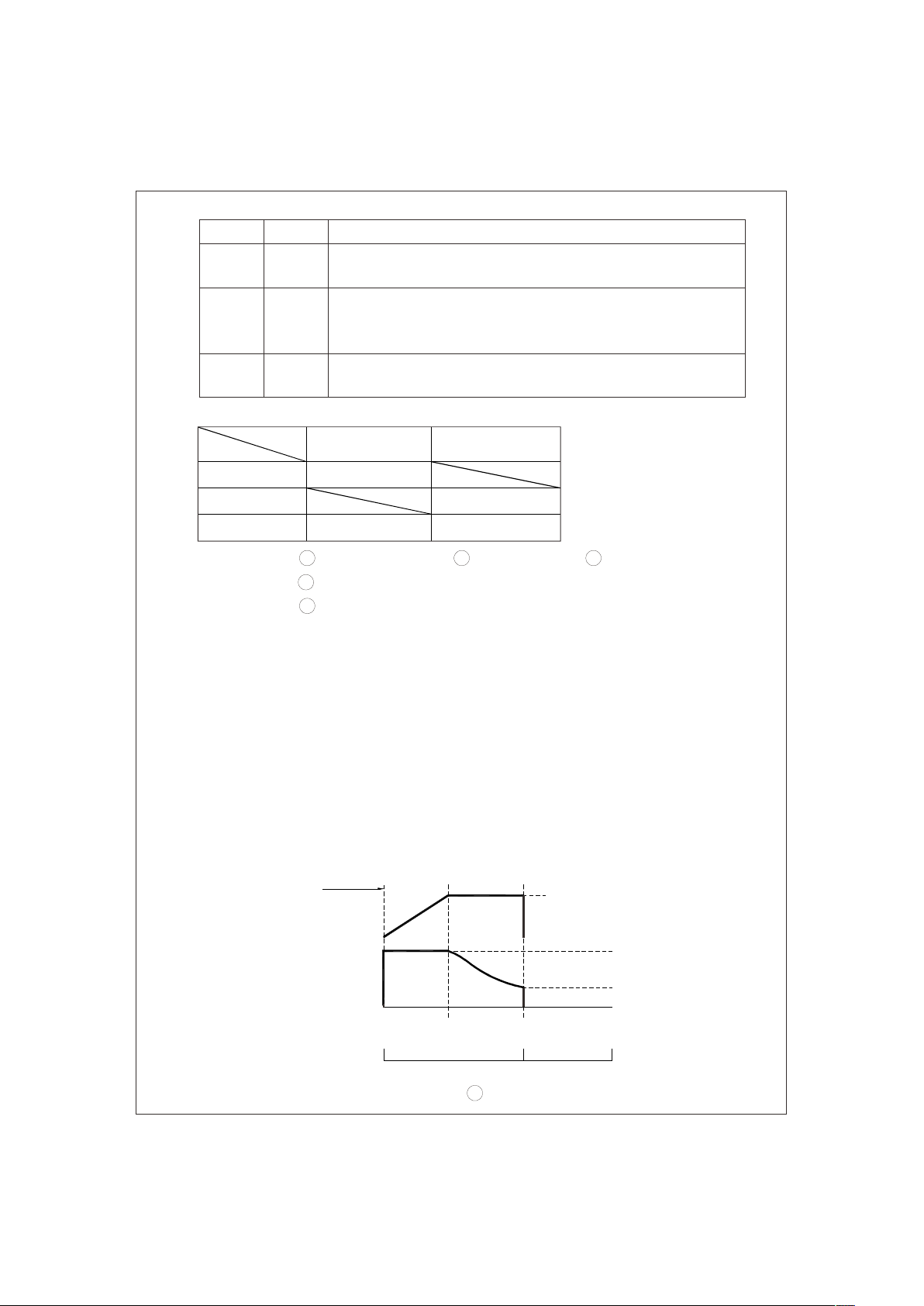
Pin No. Function
5,6
7,8
9,10
RY15
GND/RTH
RC-/ RC+
5.LED Indicati on
Co lor
Statu s
Re d
Description
Relay con tact rating (max.): 30V/1 A. "Sh ort" whe n th e un it is work in g
nor mally; “Open” when the unit is in a fa ul ty con dition
Temperature sen so r wh ich co mes wi th the charger can be co nn ecte d
to the unit to allow tempera ture compensation of the chargin g voltage .
If the temper a ture se nsor is not us ed, t he char ge r can stil l wo rk
norm ally.
Turn the ou tpu t ON a nd OFF by el ectrical or dr y co ntact bet we en
pin10 (RC+) and pin9 (RC-). Open: start charging. Short: stop charging.
St eady
Fail
Flas hin g
Orang e
Green
Typ es of failure :
Full Ch ar gin g
1
Ba ttery disconn ect ed
4
Incorrect batte ry volta ge (e .g. PB-6 00 -12 conne ct e d to 24V battery)
5
Activat ion o f pro tection function (e.g. OTP, OVP, and Short)
Ch ar gin g
2 3
Da maged ba tte ry Re ver se po lar ity
6.Exp lanatio n of op eration l ogic (charging stages ):
PB-60 0 h a s a t ota l o f 3 c h a rgin g m o d es to cho o s e f rom, 2 s t a g es, 3 st a g e s, and
8 stages. 8 stages charging differ from 2 stages with the addition of pulse , soft start,
analysis, r econd ition, float, and maintain s tages . 2 stage s provide simple and quick
charging. 3 stages is similar to 2 stages with the exception of not shutting OFF aft er
the battery is fully charged. Lastly, 8 stages will allow charging to maximum capacity.
User ca n sel ect betwe en 2,3 or 8 sta ges depending o n the ir requirement.
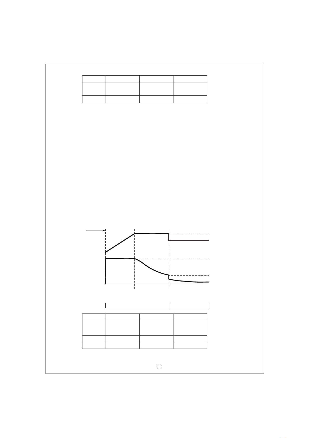
6.1 2 sta ge ch arging (f lick s wit ch to "2" sta ge)
During initial charge (stage 1), charger will provide maximum current to the battery.
The built-in fan will also turn ON. As the battery starts to get full, charging current
wi ll gra dually de crease (stage 2). When c harg ing cu rrent decr ease to less than
10% of max. LED indicator will tur n Green to sh ow a full cha rge and the c har ger
will turn OFF.
Sta rt
Charge Volt ag e
V
boo st
100%
Charge Current
Color of LED
stage 1 stage 2
Constant Cu rrent
Const ant Voltage
Orange Green
3
Bat te ry Full
10%
Page 6
State
Consta nt
Current
boo st
V
PB-600-12
PB-600-2 4 PB-600-4 8
40A 21A 10.5A
14.4V
28.8V 57.6V
Figure 6.1 2 s tag e cha rging cur ve
Expla nation fo r 2 sta ges charg ing curve
(0)In itial sta ge (b atte ry an alysis) :
Ch eck battery vol t age level t o see if i t is wit hin th e norm al ran ge, wheth e r or no t
a ba tter y is conn ected, or if th e batt e ry is al ready f ull an d further cha r ging i s not
requi red.
(1)Stage 1 ( constan t curr ent ):
A constant current is provided so the battery can be quickly charged to 2.4V per cell.
(2)Stage 2 ( constan t voltage ):
A constant voltage of 2.4 V per cel l is prov ided until the charging current n aturally
taper s down to 10% t hen s top ch arging.
6.2 3 sta ge ch arging (f lick s wit ch to "3" sta ge)
During initial charge (stage 1), charger will provide maximum current to the battery.
The built-in fan will also turn ON. As the battery starts to get full, charging current
will gradually decrease (stage 2: programmed to last no longer than 24hrs). When
charging current decrease to less than 10 % of max. LED indicator will turn Green
to show a full charge. The charger will now maintain a float charge voltage (stage 3).
Start
V
V
boost
flo at
Charge Voltage
Charge Current
Color of LED
State
Consta nt
Current
boost
V
float
V
stage 1 stage 2 stage 3
Constant Current
Constant Voltag e
Orange Green
PB-600-12
PB-600-2 4 PB-600-4 8
40A 21A 10.5A
14.4V
13.8V
28.8V
27.6V
Figur e 6.2 3 stage char ging cur ve
4
100%
10%
Battery Full
57.6V
55.2V
Page 7
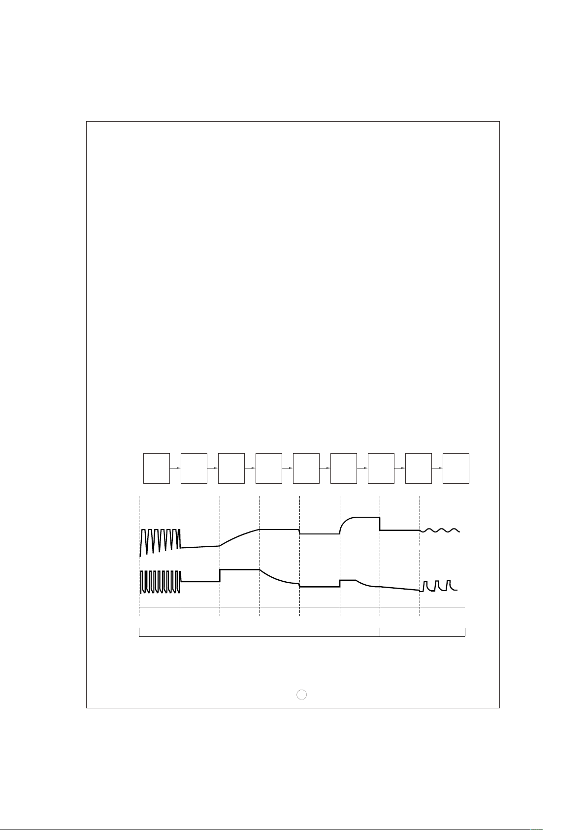
Expla nation fo r 3 sta ges charg ing curve
(0)In itial sta ge (b atte ry an alysis) :
Ch eck battery vol t age level t o see if i t is wit hin th e norm al ran ge, wheth e r or no t
a ba tter y is con nected, or i f the bat tery i s alre ady full and fu rthe r char ging i s not
requi red.
(1)Stage 1 ( constan t curr ent ):
A constant current is provided so the battery can be quickly charged to 2.4V per cell.
(2)Stage 2 ( constan t voltage ):
A constant voltage of 2.4 V per cel l is prov ided until the charging current n aturally
taper s down to 10% t hen m ove on to sta ge 3.
(3)Stage 3 ( Floa t vol tage ):
A float voltage of 2.3V per cell is provided so that the battery can maintain full charge.
*F o r a pplica t ions that u t ilize th e c harger (P B -600) to c h a rge batt e ries and s u p ply
sy ste m powe r simulta neously(e.g . UPS sy stem ), pl ease sele ct "3 st age" char ging
for the b est use of th e cha rger.
6.3 8 sta ge ch arging (f lick s wit ch to "8" sta ge)
8 stage charging provides o ptimized charge to lead acid b atter y. It also prolongs
batte ry life and incr ease s torage ca pac ity. Some o f the m ain ad van tage s are a s
below :
Advantag e of pul se stage: Use pulse curre nt to revive aged batt ery.◎
Advantag e of rec ondition sta ge: Allow fu ll charge of battery.◎
Ad v a ntage of fl o at and maint a i n stage: Afte r L E D turns gre e n , mainten a n ce ◎
charge is provided so the battery is always in a full state. User will hav e access
to a full b attery wh ene ver it is dis connect ed from the char ger.
Charg e
Voltag e
Charg e
Curre nt
Color of
LED
Start
Pul se So ft
stage 1 st ag e 2 stage 3 stage 4 stage 5 stage 6 st ag e 7 stage 8
Pulse
Charge
Start
So ft
Start
Co nst ant
Constant Constant
Current Voltage
Cu rre nt
Co nst ant
Voltag e
Ora ng e Gre en
Battery
Analysis
Ana lysis Flo at Mai ntain
Rec ond
Reconditi on
Float
Charge
Figur e 6.3 8 stage char gin g cur ve
5
Maintai n
Page 8

Expla nation fo r 8 sta ges charg ing curve
(0) Initi al stage (b attery analysis) :
Ch eck battery vol t age level t o see if i t is wit hin th e norm al ran ge, wheth e r or no t
a ba tter y is conn ected, or if th e batt e ry is al ready f ull an d further cha r ging i s not
requi red.
(1) Stage 1 ( pulse chargi ng):
Pulse cha rging is used to revive tired lead acid batter y whi ch is either impr operly
charged/discharged or allowed to self-discharge as occurs during non-use. Basically,
help to r est ore it s normal ch emi cal p rope rties.
(2) Stage 2 ( soft start):
Use l o w c h a r g e v o lt age and current to pr e p a r e t h e b a t tery to accept upcomin g
bulk charg ing, so a bet ter charg e can be appl ied.
(3) Stage 3 ( constan t cur rent):
A high constant current is provided so the battery can be qu ick ly charged t o 2.4V
per cel l.
(4) Stage 4 ( constan t vol tage ):
A constant voltage of 2.4 V per cel l is prov ided until the charging current n aturally
taper s down to a low leve l.
(5) Stage 5 ( analysi s):
Th e ch a r g e r w i l l st op charging for 2 min u t e s t o d e t e r mine battery status. I f t h e
battery vol t age is high er tha n 2.1V p er cel l, the b atte ry is de termined a s OK and
will move on to stage 6. If the battery voltage is lower than 2.1V per cell, the battery
fail in dicatio n will come ON and t he charge r will stop charging .
Stage 6 (re condition bo ost charg e):(6)
Boost voltage is provided to recondition the battery storage capacity to its original
state.
Stage 7 (fl oat charg e):(7)
A float vo lta ge of 2.3V per cell is pro vide d for e xte nded peri od of ti me(about one
day) so that t he batter y can maint ain f ull ch arge.
Stage 8 ( maintain):(8)
Ma i n t e n ance charg e i s p r o v ided to com p e n s a te for batter y s e lf -dischar g e a n d
extend battery l ife.
7.Fun ction descri ptio n
7 Inpu t voltage.1
◎Input v oltage ra nge is 90~264Vac or 127~3 70Vd c.
◎Th e provi d ed inpu t volta ge must fa ll with i n the sp e cifie d range o t herwi s e the
unit may be non-functional also the active PFC circuit may fail or get damaged.
◎Eff i c ie n cy will get lower when inp u t v o l t a g e i s a t l o w l i n e . P le ase note, load
de ratin g will be r e quire d when in p ut volt a ge is be l ow 100Va c.
6
Page 9
PF C7.2
◎Built-in active PFC circuit: PF>0.95 when input volt age is between 90~230Vac
wi th ful l loa d at the o utpu t. On th e othe r hand , if the i nput v oltage is >230V or
outpu t is no t at full loa d, the PF wil l dro p belo w 0.9 5.
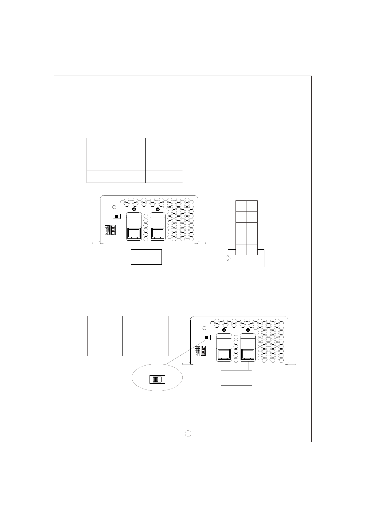
7.3 Remote contr ol
The cha rger can be t urn ed ON/OFF b y using the " remote contr ol" funct ion.
Be tween RC + (pin10)
and RC- (pin9)
SW open
SW closed
Power
Stage 8/3/2
10
+
Batt ery
Cha rge r
ON
OFF
-
1
9
SW
RY13
NC
RY15
GND
RC-
CN100
RY13
RY15
NC
RTH
RC+
2
10
7.4 2, 3, o r 8 sta ge charging mode sel ection
The charger f e a t u r e s user selec t a b l e 2 , 3 , o r 8 st age charg i n g . Th e c h a r g i n g
profi le is selected b y movi ng th e slide swi tch on the ba ck panel.
Swit ch
Slid e ri ght
Midd le
Char ging mo de
2 stag e ch arging
3 stag e ch arging
Power
Stage 8/3/2
Slid e left
8 stag e ch arging
Stage 8/3/2
10
+
-
Batt ery
7
Page 10
7.5 Rev erse pola rit y prot ect ion
With built-in battery reverse polarity detection circuit. When the battery is connected
in reverse at the output terminal of the charger, the output relay circuit will remain
open.
7.6 Fan s peed control
Wi t h built-i n f a n s peed cont r o l circuit , t he fan will au t omatic a l l y change s p e e d
depending on loa d condition.
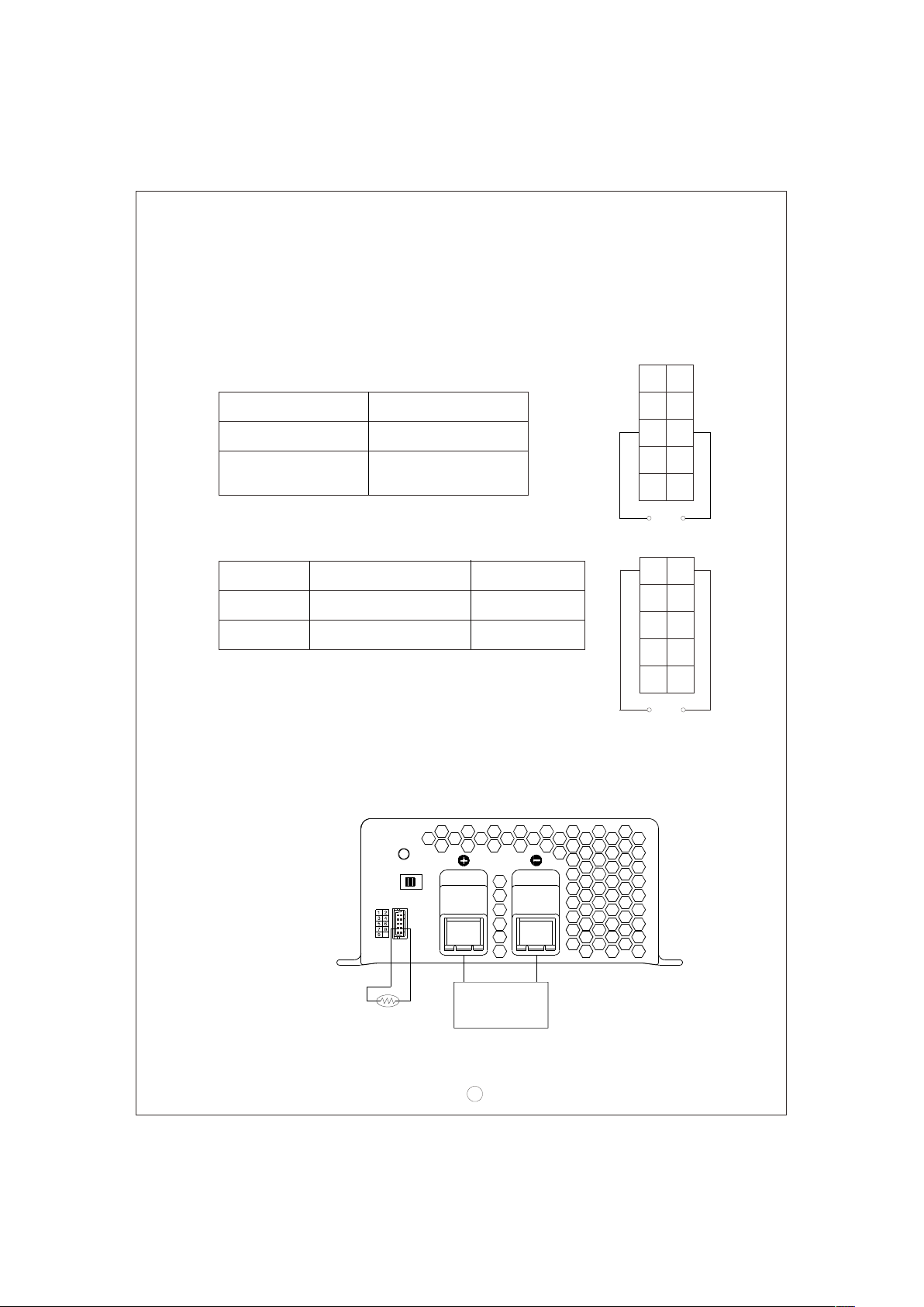
7.7 Cha rger OK rel ay (RY1 5)
Ch arg er
Work n o rma lly
Fa ilure or pr ote c ti on
fu nction ac ti v ate d
Be t wee n p in 5 a nd pin6
7.8 Out put OK relay (RY13 )
Battery
Battery full
Charging
Between pin1 and pin2
ON (short ) Gree n
OFF (open) Orange
ON ( s hort)
OF F ( ope n)
Colo r of LED
CN1 00
RY13
RY13
1
NC
NC
RY15
RY15
GND
RTH
RC-
RC+
9
1
RY13
NC
RY15
GN D
10
RY1 5
CN1 00
RY13
NC
RY15
RTH
2
2
RC -
RC +
9
10
RY1 3
9 Tempe rature co mpe nsation7.
Temperature sensor which comes with the charg er can be c onnected to th e unit
to allow temp erature co mpensation of the char ging voltage. If th e temperature
senso r is no t used , the c harger ca n sti ll wor k nor mall y.
Power
Stage 8/3/2
10
The te mp erature
sens or can ei th er
be att ac hed t o the
batt ery or placed
in its s urrou nding
envi ronme nt.
NTC
+
8
-
Battery
Page 11
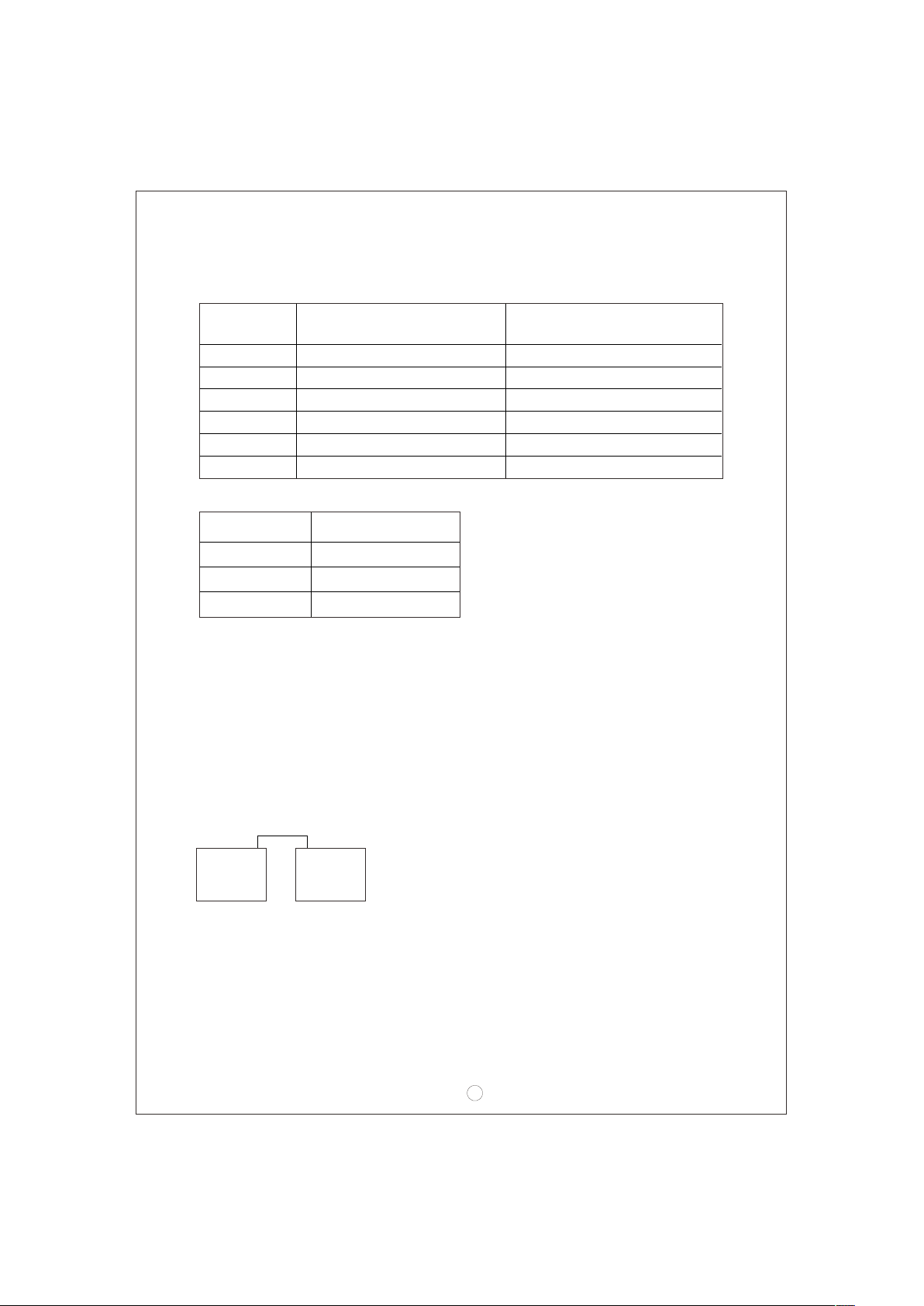
8.Wir ing for ba tter y
Se lect su itabl e wire gu age based on rat ed cha r ging cu rrent . Refe r t o the fo l lowing
table for minimum wire gauge. We highly recommend using RED wire for + connection
and BLA CK wire for -co nnec tio n:
AWG
CROSS SECTION(mm )
2
Max. Curr ent(A)
UL1015(600 V 105 )℃
14 2.1 12
12 3.3 22
10 5.3 35
7 10 46
6 16 60
4 25 80
9.Sug gested battery capaci ty
Model
Battery capacit y
PB-600-12 135-400AH
PB-600-24
PB-600-48
70-2 10AH
35-1 05AH
Note: 1.Using battery capacity larger than the suggested value will not lead to damage
of t h e b a ttery. The m a i n d r awback is it m a y t a k e longer to ful l y c h a rge the
batte ry.
2.If you're unsure about max allowable charging current of your battery, please
refer t o the b attery' s technic al spe cif ication o r consult i ts manufactu rer.
10.Se rie s and pa ral lel co nne cti on of ba tte ries
1.Bat teries in seri es
Volt a g e c a n b e d o ubled when 2 b a t t e r i e s are connec t e d i n s e r i es. However, t h e
capacity (Ah) will remain the same. For example, 2 x 12V 100Ah batteries connected
in seri es = 24V 100Ah.
++
--
Batt eryBatter y
9
Page 12
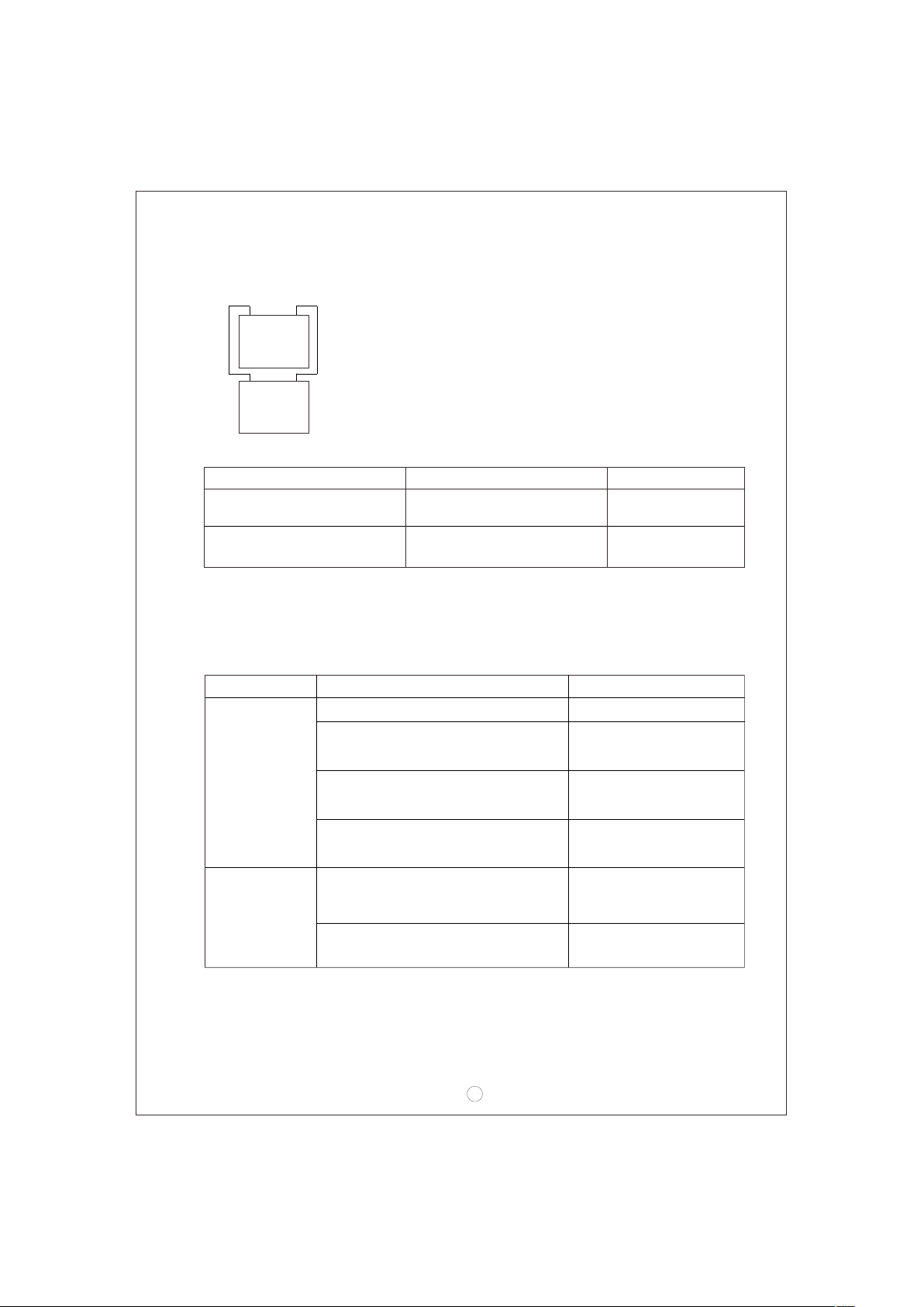
2.Bat teries in para llel
Wh e n 2 b at t er i e s ar e c onn e c t e d i n pa r a l l e l, v o l ta g e re m a i n s t h e s a m e an d t h e
capac ity (Ah) do ubles. Fo r exa mple, 2 x 12V 1 00Ah batteri es con nected in para llel
= 12V 200 Ah.
+
+
-
Batter y
-
Batter y
11.Rec ommende d wir e spec ifi cation
Inst allat ion
Desk top, counter t op, chass is
box (m ob ile )
Grou nded, fixed in place
(not m obile )
SP-2, SPE-2, SPT-2,S V,SVE,SVT
S, SE, S O, SP-3, SPT-3, ST, STO,
SJ, SJ E, SJO, SJT, SJTO
Safe ty rati ng Maxi mum len gth
10ft ( 3 meter )
Not spec ified
Note: Pleas e install i n acco rdance wi th the t able a bove. Wire gauge sho uld be n o
smaller than No. 18 AWG/3C. Socket type restricted to 15A, 125V (NEMA 5-15P)
or 15A, 250V(NEMA 6-15P) w ith powe r cor d len gth rang ing f rom 1.8 meters
to 10 met ers.
12.Fa ilure cor rec tion n ote s
Statu s
Possi ble reaso ns
Solut ion s
ON/OFF switch in the OF F positio n Switch to the ON position
Batte ry revers e pol arit y
Recon nec t usin g the
right p olarity
Unabl e to
charge
the bat tery
Batte ry with hig her v olta ge is
conne cted
Use batter y with the
corre ct voltage
Ma ke su re input so urce
is betw een 90~26 4VAC
Repla ce wi th a new
batte ry
LED ind ica tor
does no t tur n
Input AC v oltage is too lo w
Batte ry ex ceeded lifesp an or
damag ed
Green a fter a
long ch arging
perio d
Outpu t cab les are too thin
Repla ce wi th sui tab le
wire ga uge
If you ar e not a ble to clea r the failu re condition , plea se co ntact Mea n Well or
any of ou r dis trib utors for repa ir servic e.
10
Page 13

N o . 2 8 , Wu q u an 3 r d R d. , W u g u Di s t ., N e w Ta ip e i C it y 2 48 , Ta i wa n
 Loading...