

Page 1
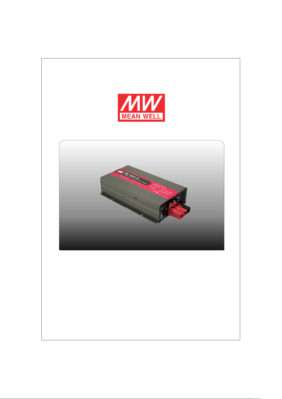
PB-1000
Instruction Manual
Page 2

PB-1000 Instruction Manual
Index
0.Product description.............. ................................................................. ..
1.Notes on operation
2.Front and back panel
3.Derating curve
3.1 Ch arging current VS tempera ture
4.Func tion description for CN100
5.LED Indication
6.Explanation of operation logic (charging stages)
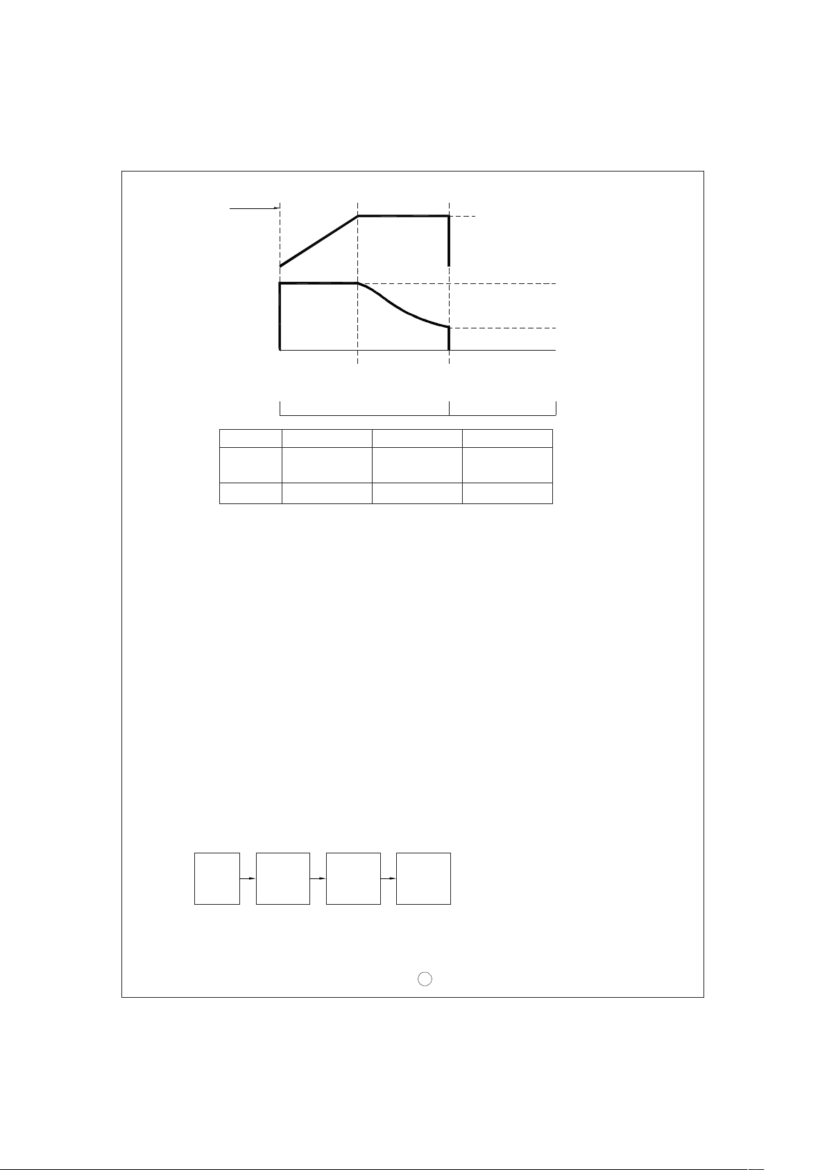
6.1 2 stage charging (flick switch to "2" sta ge)
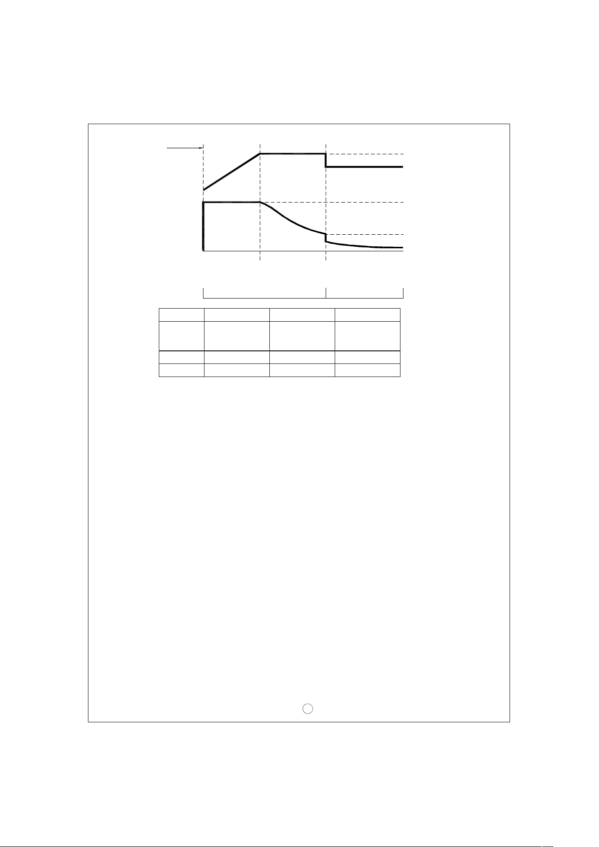
6.2 3 stage charging (flick switch to "3" stag e)
36. 8 stage charging (flick switch to "8" stage)
7.Func tion description
7.1 Input voltage
7.2 PFC
7.3 Remote control
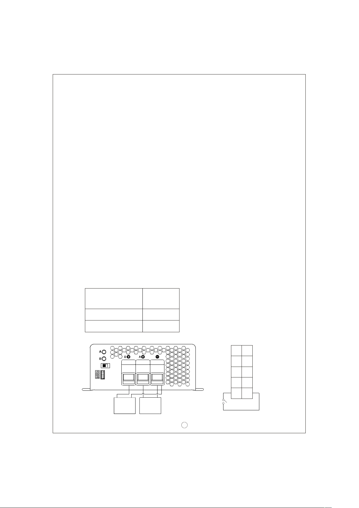
7.4 Two battery banks
7.5 2, 3, or 8 stage charging mode selection
7.6 Reverse po larity protectio n
7.7 Fan speed contr ol
7.8 Charger OK relay (RY15)
7.9 Output OK relay (RY13 & RY14)
7.1 0 Temperatu re compensation
8.Temperature compensation
9.Suggested battery capacity
10.Series and parallel connection of batteries
11.Failure correction notes
.... .......................... ....................................... ............................
....... .............................................. ............................
..................................... ....................................... ..
.................................. ......................................................
....................................... ...............
...................... .........................................
.................................. ......................................................
......................................
....................................... ..
....................................... ..
....................................... ..
..... .............................................. ............................
.... .......................... ....................................... ...............
....... .............................................. ............................
...................... ......................................................
............... ............................
...................... .........................................
... .............................................. ............................
..... .............................................. ...............
..................................................... ..
.......................................................... ..
....... .............................................. ...............
............... ......................................................
... .........................................
............................... .........................................
1
1
1
2
2
2
3
3
3
4
5
7
7
7
7
8
8
9
9
9
9
10
10
10
11
11
Aug. 2013 Version 7
Page 3
0. Produc t des cr ip ti on
PB-100 0 is MW's next generation smart charg er. It has many of the protective features
th a t consu m ers wo u ld like t o h ave in a ch a r g er i n cludi n g ba tte r y m i sco n nectio n
(wrong voltage), reve rse polarity, battery disconnection or not connecte d, and battery
fai l ure analy si s. The latest hi gh effi cien c y sw itchi ng t op olog y plus microc ontro ller
po wer m anagement ar e uti l i ze d i n its d e sig n. T hree t yp e s of charging cu rve s ar e
offered for lead a cid ba ttery cha rgin g, 2 stag es for quick c har ging , 3 st age s (qui ck +
flo a t), and 8 st ages for optimize d chargin g. C harging stage sel ection c an b e ea sily
made by th e us er thr ough th e sel ection switc h on the fr on t pa nel.
Depending on battery brand and type (lead acid, gel, lithium iron, and lithium manganese);
th e ba t tery ma y r equ ir e s pe cial chargin g curves an d adj u stm en t t o the p rotect iv e
function s which diffe rs from the standard settings. The charging curves and protective
functions can be customized by reprogramming its firmware. Basically, you can change
the voltage/current settings of each individ ual stage plus adjust or cancel the protectiv e
fun ctio ns. Plea se note, the fa ctor y chargi ng c urv e is for charging l ead-acid batt ery.
Plea se con tact MW rega rding other t ypes of batt ery c harg ing requiremen t s.
1. No tes on oper a tion :
◎Des igne d f or c ha rg in g lead acid bat te ry.
◎Mus t be installed in a dry and well ventilated area. It sho uld not be expos ed to rain
or snow.
◎Th e cab les betw e en c harg er and b at t ery s hou ld be ke pt as sh ort as po s si b l e to
prevent exces sive vol tage drop. Too much voltage drop will lead to longer charging
peri od.
◎Pl ea s e make s ur e chargi n g vol tag e and c urrent meet s battery s pe c if icatio n .
◎Refr a i n from con necting new a nd old b at t e ries in s eri e s.
◎Char g er s hould be in t he OFF m od e b efo re m a kin g bat tery connec tio n or dis con nec ti on.
◎Thre e years w ar ran t y is p rov ide d un der nor m al o per a t ing co n ditions . Fa ilur e
resulting from im pro p er o p er a tio n wi l l res u lt i n cancel l at ion of war r an t y.
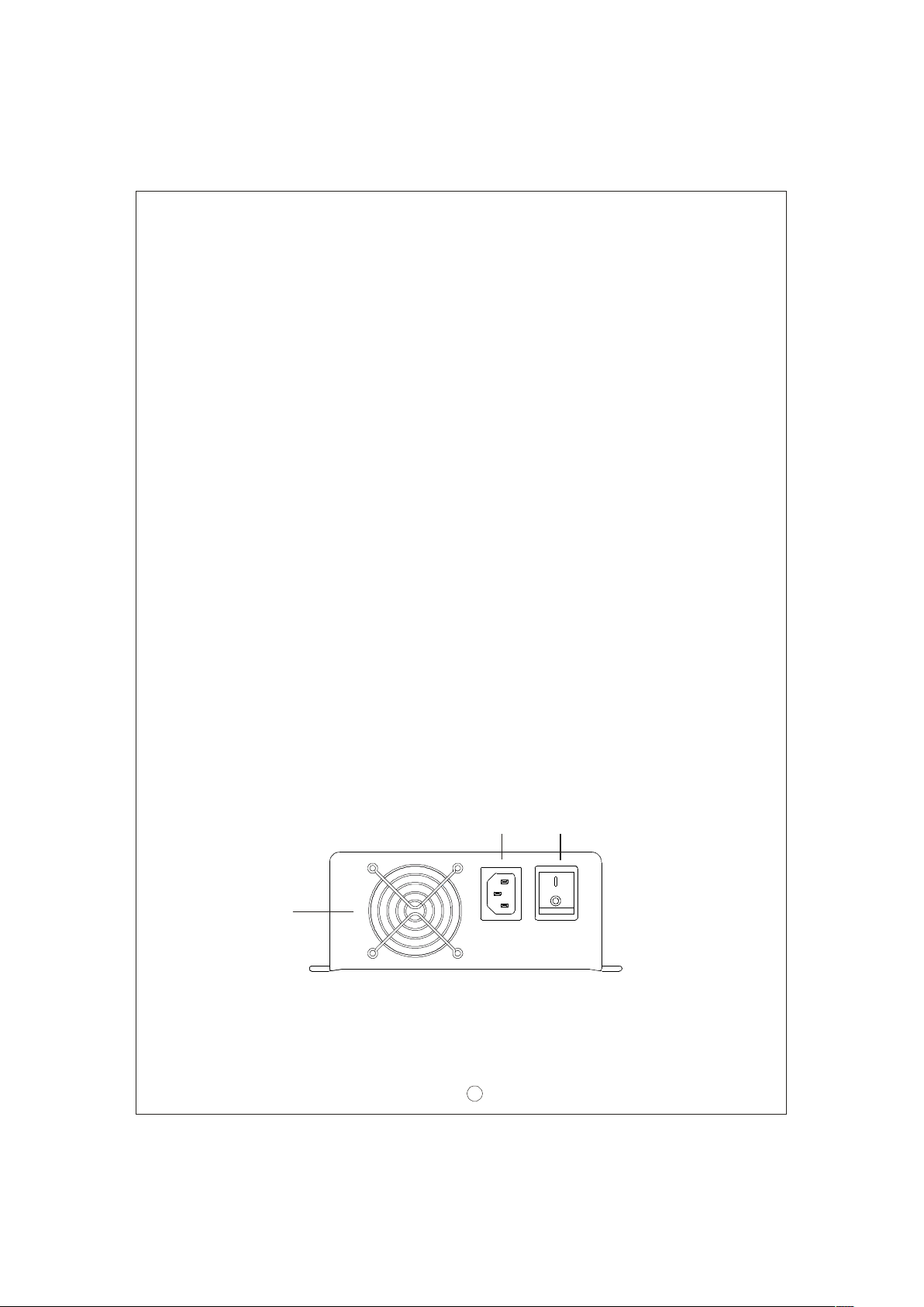
2.Front and back panel
F an
Ve ntilat ion
H ol e
AC I NLET
AC INPUT
ON/OFF SWIT CH
Figu re 2.1 Fr on t Pa ne l
1
ON
OFF
Page 4
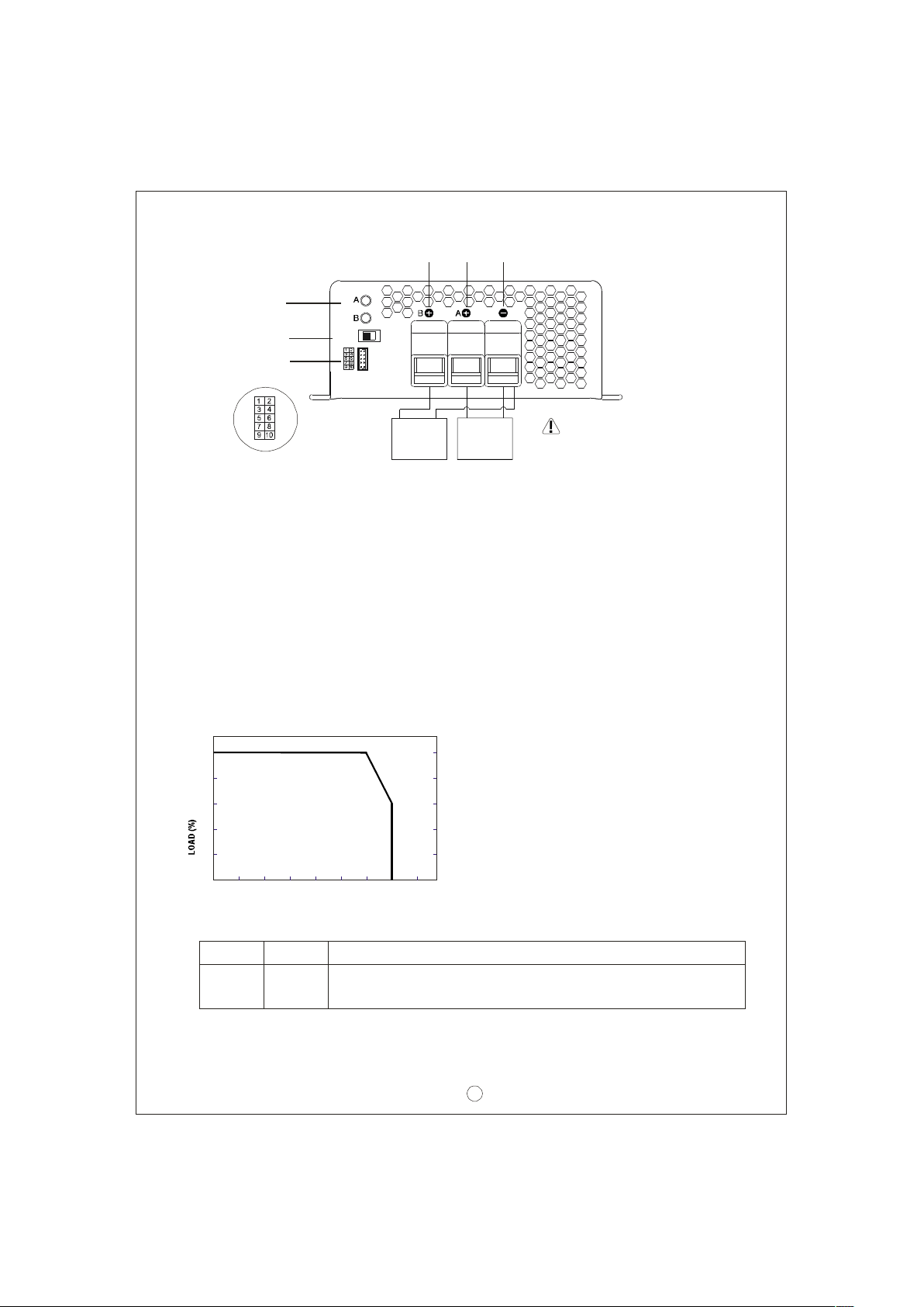
Battery B
Positive
Battery A
Positive
Common
Neg ative
LED
Indi cator
2/3/8 stage
{
Stage 8/3/2
se lectio n s w itch
Func tion
Connec t or
+
-
+
-
Battery ABattery B
WARNING :
Pl ease che ck batter y
po larity befo re
Figu re 2.2 Ba ck P anel
co nnection
Asse mb ly guide li ne s:
1. The charger should be turne d OF F pr ior to battery con nection. Sui tabl e wire gau ge
should be chos en based on ra ted charging cu rrent of the charg er unit. Double -ch eck
battery polarity before making the battery connection. Positive terminal of the charger
must be co nnect ed to + o f th e batte ry and ne gativ e te rminal to of the b attery. Also,
ma ke sure t he posi t ive and n eg ative terminal s of the ch a rger are not a cc identall y
shorted toge th er.
2. Afte r p l ugg i ng in th e AC po w er cab l e, fli ck the ON/OFF ( 0/-) s w i tch t o the ON(-)
positio n . The LED in dica to r on the switc h will ligh t up.
3. De rating c urve
3. 1 Charging c urren t VS tempe rature
100
80
60
40
20
-20 0 10 20 30 40 50 60 70
AMBIENT TEMPE RATURE ( )℃
4. Fu nction desc ription f or CN100
Pin No. Function
1,2 RY13
Descripti on
Rela y con ta ct rat ing (m ax.): 30V/1A. "Sh ort" w hen bank A is full.
"O pen" when b an k A is stil l charg in g.
(HORI ZONT AL)
2
Page 5
Pin No. Function
3,4
5,6
7,8
9,10
RY14
RY15
GND/RTH
RC-/R C+
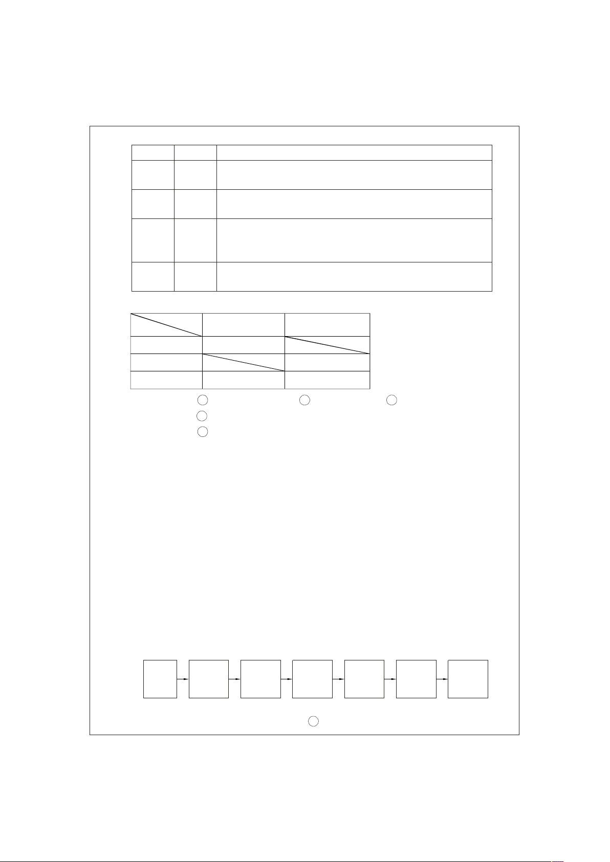
5. LE D In dication
Descripti on
Rela y con ta ct rat ing (m ax.): 30V/1A. "Sh ort" w hen bank B is f ull .
"O pen" when b an k B is sti ll cha rging .
Re lay contac t ra ting (m ax.): 30V/1A . "Short" when th e unit is working
prope rl y. "O pen" w hen th e unit has failed o r protect io n has activ ated.
Temperature sensor which comes wit h the char ger ca n be connected
to the unit to allow temperature compens ation of the charging v olt age.
If the tem peratur e s en sor is not u sed, th e charger ca n s ti ll w o rk
no rma lly.
Turn the output ON and OFF by electrical or dr y c ontac t be tween
pin10 (RC+) and pin9 (RC-). Open: start charging. Short: stop charging.
Co lor
Types of failu re:
St atu s
Re d
Orange
Green
Stea dy
Fa il
Fu ll Charging
1
Ba ttery disconnec ted
4
Incorrect batt er y vo ltage (e.g. PB-1000- 12 co nn ec te d to 24V batt ery)
5
Ac tivation of pro te ction function (e.g. OTP, OVP, and Short)
Flashing
Charging
2 3
Damaged bat te ry Rever se pola ri t y
6. Ex plan ation of ope rati on l ogic (charg in g stag es):
PB - 10 0 0 has a t ot a l of 3 ch argi ng mo des to c ho o se from, 2 stages, 3 sta g es , and
8 stages. 8 stages char ging diffe r from 2 stag es with the addition of pulse, so ft start,
analysis, re condition, fl oat, and maintain sta ges. 2 st ages pro vide sim ple an d quick
charging. 3 stages i s sim ilar to 2 s tages with the excep tion of not shutt ing OFF afte r
the battery is fully charged. L astly, 8 stages will allow charging to maximu m capacity.
User can select betwee n 2, 3 or 8 stag es d ep endin g on th eir requi rement.
6.1 2 s tage char gi ng (fl ick switch to "2" st age )
PB-1000 ha s ch annels A & B whi ch can pe rfo rm 2 stag es c hargin g indi vidua lly.
Cha nne l A wi ll be the first to commence ch arg ing. D uri ng initial charge (s tag e 1) ,
cha rger will provide max imu m cu rrent to the battery. The built-in fan will also turn
ON . As t he bat t e ry s tar t s to get f ull , cha r gi n g cu rre n t will gradu a l ly d e crease
(sta ge 2). When charging cur rent decrease to less than 10% of m ax. LED indicato r
wi l l t ur n Gr een t o s h ow a full ch a rge. Ch an n el A will tur n OF F w hil e cha r ging
com mence a t Channel B. After the battery at chan nel B is fully cha rged, PB-1000
wil l turn OF F its outp uts.
St a rt
B a nk A
C onstant
C ur rent
Ba nk A
Const a nt
Volta ge
Ba nk A
Charging
En ds
3
Ba nk B
Consta nt
Curre nt
Ba nk B
Consta nt
Volta ge
Ba nk B
Charging
En ds
Page 6
Start
Charge Voltage
V
boo st
100%
Charge Current
10%
stage 1 stage 2
Color o f LED
State
Constan t
Current
boost
V
Const ant Cur rent
PB-10 00-12
60A 34.7A 17.4A
14.4V
Constant Voltage
Battery Full
Orang e Green
PB-1000-24 PB-10 00 -48
28.8V 57.6V
Fig ure 6.1 2 stag e ch arging curve
Explanatio n f or 2 stages char g ing curve
(0)Init ial sta ge (bat te ry a na lysis):
Chec k ba ttery vo ltage le vel to see if it is within th e no rmal rang e, whether or not
a ba tt er y is conn ected, or if the batte ry is a lready full and furth er ch argi ng is not
req u ired .
(1)Stage 1 ( cons ta nt current):
A constant current is provided so the ba ttery can be quickly charged to 2.4V per cell.
(2)Stage 2 ( cons ta nt voltage) :
A co nst a nt voltag e of 2.4V per cel l is provided unt il the charging current naturally
tap ers d own to 10% then stop char gin g.
6.2 3 s tage char gi ng (fl ick switch to "3" st age )
PB-1000 can only pe rfor m 3 stag es char ging to Channel A. Du ring ini ti al charg e
(sta ge 1 ), c harger will provi de maxi m um curren t to the ba ttery. The b uilt - i n fa n
wil l also turn ON. As the batt ery star ts to g et f ull, c harg ing current will gradually
dec rea se (s tag e 2: programmed to l a st no lo nge r th a n 24hrs). W hen c ha r gin g
cur rent d ecreas e to less than 10% of max. LED in dicator will turn Green to show
a fu ll ch arg e. The cha rger will no w main ta in a float ch arge voltage (st a ge 3).
St a rt
B a nk A
C onstant
C ur rent
Ba nk A
Const a nt
Volta ge
Ban k A
Floa t
Cha rg e
4
Page 7
Start
Charge Voltage
V
boo st
V
fl oat
100%
Charge Current
10%
stage 1 stage 2 stage 3
Col or o f LED
State
Constan t
Current
boo st
V
float
V
Const ant Current
PB-10 00-12
60A 34.7A 17.4A
14.4V
13.8V
Constant Vo ltage
Battery Full
Orang e Green
PB-1000-24 PB-10 00 -48
28.8V
27.6V
57.6V
55.2V
Figure 6 .2 3 s tag e ch arging cur ve
Explanatio n f or 3 stages char g ing curve
(0)Init ial sta ge (bat te ry a na lysis):
Chec k ba ttery vo ltage le vel to see if it is within th e no rmal rang e, whether or not
a ba tt er y is conn ecte d, or if th e batter y is alre ady f ull and furth er charg i ng i s no t
req u ired .
(1)Stage 1 ( cons ta nt current):
A constant current is provided so the ba ttery can be quickly charged to 2.4V per cell.
(2)Stage 2 ( cons ta nt voltage) :
A co nst a nt voltag e of 2.4V per cel l is provided unt il the charging current naturally
tap ers d own to 10% then mo ve on to stage 3.
(3)Stage 3 ( Float vo ltag e):
A float voltage of 2.3V per cell is provided so that the battery can maintain full charge.
*For application s th at utilize the charger (PB-10 0 0) to char ge b at teries and su pply.
System power simu ltan eou sly(e .g. UPS system ), please sele ct "3 stage" cha rgin g
fo r the be st us e of t he c har g er.
6.3 8 s tage char gi ng (fl ick switch to "8" st age )
8 stage c hargi ng provide s op timized charge to lead acid batter y. It also prolongs
bat t ery li fe a nd i ncre ase storage cap acit y. Some o f th e ma in advantages are as
bel ow:
Adva ntag e of puls e st age: Use puls e cu rren t to revi ve aged batt ery.
◎
Adva ntag e of reco ndition stage : Allow f ull char g e of ba t tery.
◎
5
Page 8
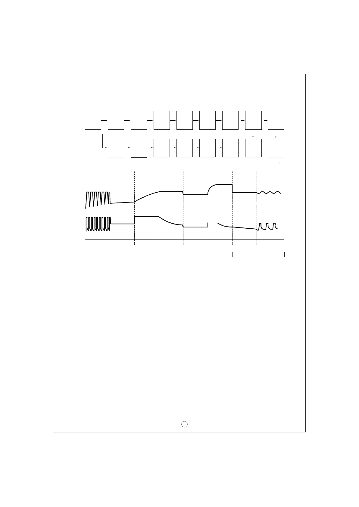
Advantag e of float an d ma i nt ain st age: Aft e r LE D t urns gr e e n, m ai n ten ance◎
charg e is p rov ided so t he battery is always in a full s tate. Use r wil l have ac cess
to a fu ll battery whene v er i t is disco nnected from the charg e r.
B ank A
R econ di ti on
B ank B
R econ di ti on
A/ B main tai n cha rge cycl e
Re cond
Bank A
Floa t
Charg e
Bank B
Floa t
Charg e
Cha rge
Volt age
Cha rge
Cur ren t
Color of
LED
Start
Ban k A
Sof t
St ar t
Ban k B
Sof t
St ar t
St ar t
stage 1 sta ge 2 sta ge 3 stag e 4 stage 5 sta ge 6 st age 7 stage 8
Bank A
Pulse
Cha rge
Bank B
Pulse
Cha rge
Pu lse Soft
Bank A
Constant
Current
Bank B
Constant
Current
Constan t
Cur ren t
Ora nge Gre en
Cons ta nt
Volt ag e
Bank A
Constant
Voltage
Bank B
Constant
Voltage
Ban k A
Analysis
Ban k B
Analysis
Ana lysis Float Mai ntain
Figure 6 .3 8 s tage c harg ing curve
Explanatio n f or 8 stages char g ing curve
(0)Initia l stage (b at tery anal ysis ):
Chec k ba ttery vo ltage le vel to see if it is within th e no rmal rang e, whether or not
a ba tt er y is conn ected, or if the batte ry is a lready full and furth er ch argi ng is not
req u ired .
(1)Sta ge 1 (pulse charg in g) :
Pul se charg ing is use d to rev ive tired le ad acid battery whic h is eith er impro perly
charged/discharg ed or allowed to self-discharge as occurs during non-use. Basically,
hel p to re stor e it s no rmal che mi c al pro pert ies.
(2)Sta ge 2 (s oft start):
Use l ow cha rge v ol t a ge and c ur r e nt to p repa re th e battery to a cce pt u pcomi n g
bul k ch argi n g, so a bett er char ge c an b e applie d.
(3)Sta ge 3 (c on stan t cu rren t):
A hi gh constant c urre nt is provided so the batt ery can be qu ickly ch arge d to 2 .4V
per cell.
(4)Sta ge 4 (c on stan t vo ltag e):
A co nst a nt voltag e of 2.4V per cel l is provided unt il the charging current naturally
tap ers d own to a low l evel.
Ban k A
Mainta in
Ban k B
Mainta in
6
Page 9
(5)Sta ge 5 (ana lysi s):
The c ha r ge r w ill stop ch a rgi n g fo r 2 m inu t es t o determ ine bat t er y s ta tu s. If th e
batt ery volt age is high er tha n 2. 1 V pe r cel l, the battery is d eter mi ned as OK and
will move on to stage 6. If the battery voltage is lower than 2.1V per cell, the battery
fail indic atio n wi ll come ON and th e ch arge r will stop charg ing .
Sta ge 6 (rec ondi tion boost char ge):(6)
Boost vo ltage is provided to re con ditio n the battery stora ge cap acity to it s original
stat e.
Sta ge 7 (f loat ch ar ge):(7)
A float vol tag e o f 2.3V per cell is prov ided for exte nded period o f time so th at the
bat t ery can main tain ful l c harg e.
Sta ge 8 (maintai n):(8)
Maintena nce ch arge is prov i d ed t o compens ate f or ba tt e r y se lf- d ischarg e an d
ext end batt ery life.
7. Fu ncti on d esc ription
7 Input v o ltage.1
◎Input volt age range is 90~2 64Vac o r 12 7~37 0V dc.
◎Th e pr ov ided input voltag e mus t fa ll wi thin the s pe cifie d ra nge othe rwise the
unit may be no n-func ti onal also the active PFC c ircuit may fa il or get d amaged.
PFC7.2
◎Built- in active PFC circuit: PF> 0.95 when input voltage is be twe en 90~ 230Vac
with f ull load at the output . On t he othe r ha nd, if the input vo ltage is >230V or
output is not a t fu ll loa d, the PF wi ll dro p be low 0.95.
7.3 Re mote contr ol
The char ge r can be t urned ON/O FF by usi ng t he " remo te con trol " f unct ion.
Betwee n RC+ (pin10)
an d RC - (pin 9)
SW o pen
SW c losed
Stage 8/3/2
+
-
Battery B
Charge r
+
Ba tte ry A
ON
OFF
-
CN1 00
RY13
RY14
RY15
RTH
RC+
2
1 0
1
9
SW
RY13
RY14
RY15
GND
RC-
7
Page 10
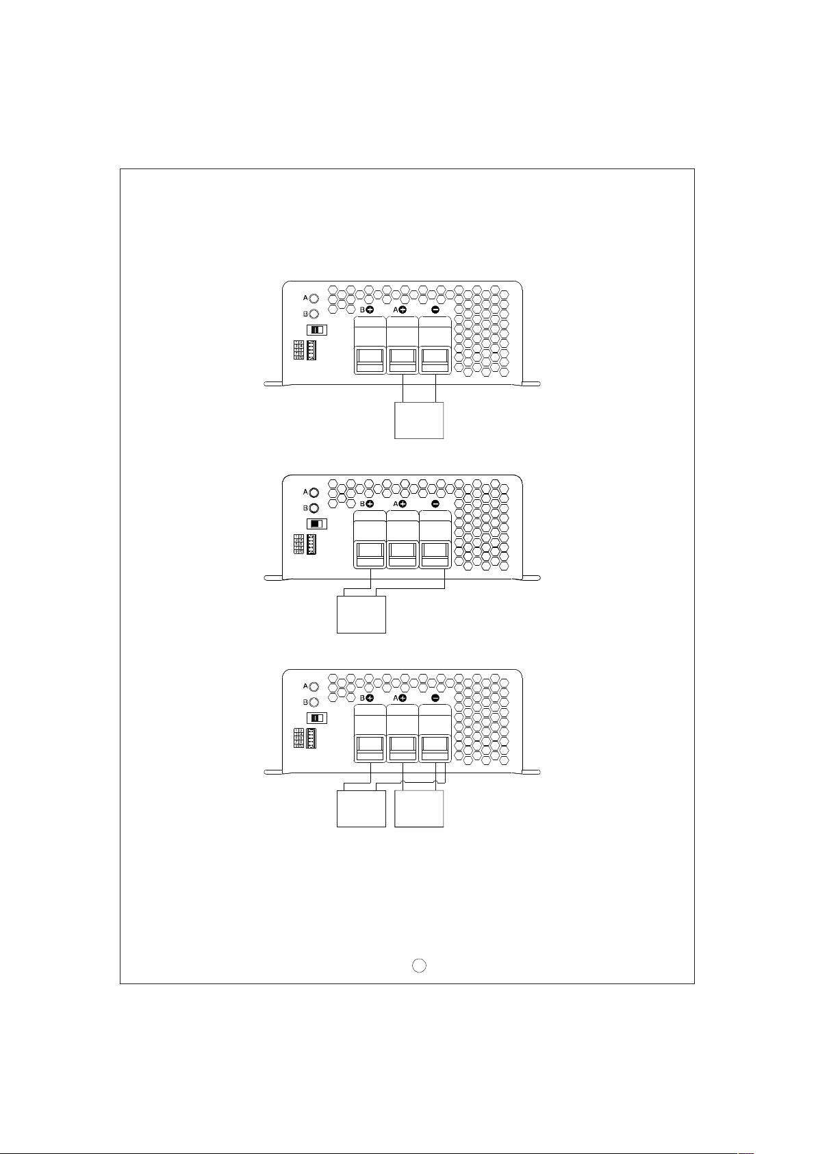
7.4 Two battery banks
The cha r ger ca n be hoo k ed up t o two ba t ter y banks (A and/or B) . Connect th e
bat tery bank (s) as below. If you are connectin g 2 batte ry banks at t he same time,
kee p in mind tha t it m us t sha re a c om mon ground .
Stage 8/3/2
+
-
Ba ttery A
Stage 8/3/2
+
-
Battery B
Stage 8/3/2
+
-
+
Battery B
-
Ba ttery A
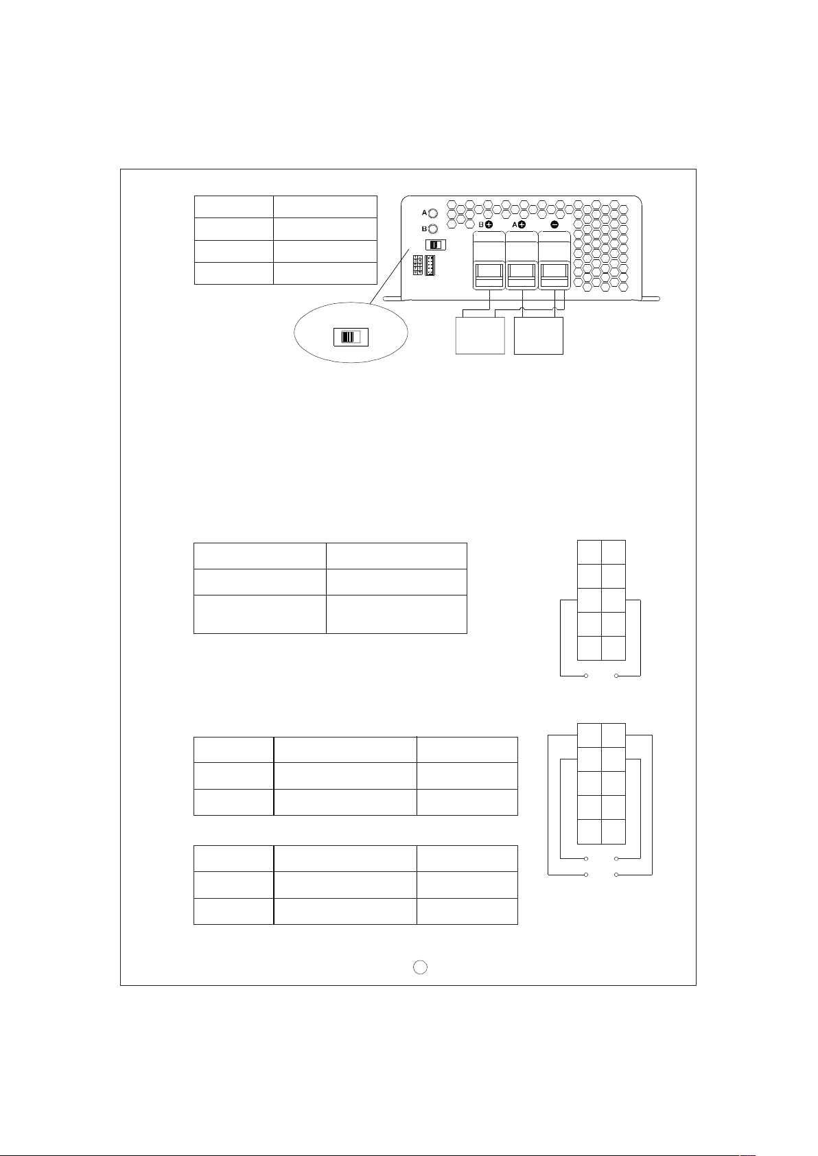
7.5 2, 3 , or 8 sta ge c ha rgin g mode sel ectio n
Th e ch arge r fe a t ures us er sel e cta b l e 2, 3, o r 8 s t ag e ch a rgi ng. T he cha r gi n g
pro f ile is sel ecte d by moving t he s lide sw itch on the ba ck p anel .
8
Page 11
Swi tch
Slide right
Middle
C harging mo d e
2 stage chargi ng
3 stage chargi ng
Stage 8/3/2
Slide lef t
8 stage chargi ng
Stage 8/3/2
+
Ba tt ery B
-
+
Ba tte ry A
-
7.6 Re vers e po larit y p rote ction
With built-in battery reverse polarity detection circuit. When the battery is connected
in rever se at the outp ut te rmi nal of the cha rge r, the out put r elay circuit will remain
ope n.
7.7 Fa n sp eed control
With bu ilt-i n fan sp eed c on t rol c ircuit , th e fan will automa tica l ly ch an g e speed
dep ending on load cond i tion .
7.8 Ch arge r OK re l ay ( RY1 5)
Ch ar ger
Wor king n or mal l y
Fa ilure or p ro tection
fu nc tion ha s ac ti vated
Be twe en pi n5 and pin 6
ON (s ho rt)
OFF ( ope n)
CN 100
1
RY13
RY13
RY14
RY14
RY15
RY15
GND
RTH
RC -
RC+
9
2
10
7.9 Ou tput OK rela y (RY13 & R Y14)
1.Ban k A OK ( RY1 3)
Bank A
Bank A full
Cha rgin g
Bet ween pin1 and pin2
O N (s hort)
OF F (o pen )
2.Ban k B O K (RY14)
Bank B
Bank B fu ll
Cha rgin g
Bet ween pin3 and pin4
O N (s hort)
OF F (o pen )
Co lo r of LED A
Gree n
Orange
Col or of L ED B
Gree n
Orange
9
RY15
CN 100
RY14
RY13
RY13
RY14
RY15
RTH
RC+
2
10
1
RY13
RY14
RY15
GND
RC-
9
Page 12
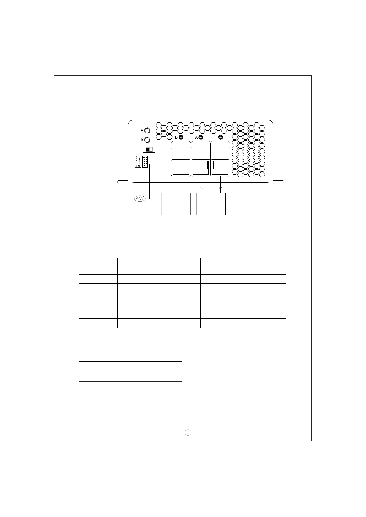
10 Te mperat ure com p en sation7.
Tempe rature se nso r which c omes wi th th e ch arg er can be con nec ted to the unit
to allow temper atu re co mpensation of the ch arging vo ltage. If the tem perature
se ns or is not used, th e ch ar ger can still work no rmally.
Stage 8/3/2
The t empera ture
senso r can either
be at tach ed to the
batte ry or placed
in it s surrou nding
env ir onment.
NTC
++
Battery ABa ttery B
--
8. Wiri ng f or b at te ry
Select suit able wire gu age based on rat ed charging curr ent. Refer to the follo wing
table for minimum wire gauge. We highly recommend using RED wire for + connection
and BLACK wire for -connection:
AWG
CROSS SECTIO N(mm )
2
Max. Current( A)
UL10 1 5(60 0V 105 )℃
14 2. 1 12
12 3. 3 22
10 5. 3 35
7 10 46
6 16 60
4 25 80
9. Su ggested ba ttery capacity
Mo de l
Battery capacity
P B-10 00- 1 2 200-600AH
P B-10 00- 2 4
P B-10 00- 4 8
120-350A H
60-175AH
Note: 1.Using battery capacity larger than the suggested value will not lead to damage
of the bat tery. Th e main drawback i s it may take lo nger t o fully ch arg e the
ba tter y.
2.If you're unsure about m ax allowable cha rging current of your battery, please
re fer to the ba tt er y' s tec hni c al s peci fication or cons u lt its man ufactu re r.
10
Page 13
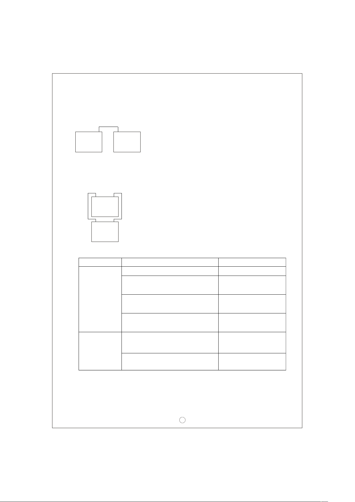
10.S erie s an d pa rallel conne ction of batteries
1. Ba tt er ies in series
Voltag e can be double d when 2 batteri es ar e c o nn e cted in s er i es. H ow eve r, th e
capacity (Ah) wi ll remain the s ame. For example, 2 x 12V 100Ah batter ies connec ted
in seri es = 24V 100 Ah.
+
Batte ry
-
+
Ba ttery
-
2. Ba tt er ies in paralle l
When 2 ba tt er ie s a r e c onn e cted in pa rall e l, volta g e r e ma i n s t h e same an d th e
capac i ty (Ah ) doub les. F or e xample , 2 x 12V 100Ah batte ries c on necte d in pa r allel
= 12V 200Ah.
+
-
Ba ttery
+
-
Ba ttery
11.Fa ilur e co rrec tion notes
Status
Poss ib le rea sons
Solu tion s
ON/O FF switch in th e OFF position Switch to the ON pos ition
Ba tter y re verse pol a rit y
Reco nn ect us ing the
right pola rit y
Unabl e to
cha rge
the batt ery
Ba tter y wi th highe r volta ge is
con nected
Use bat ter y with the
correc t vo ltage
Ma ke s ur e input sou rce
is b etween 90~264 VAC
Repl ace with a new
batter y
LED indicato r
doe s not tur n
In put AC vol tage is too low
Ba tter y ex ceeded lifespan or
dama ged
Gre e n af ter a
lon g ch argin g
per i od
Out put cables a re too thi n
Repl ace with su itable
wire gauge
If you are not abl e to clear th e fa ilure co ndition, plea se c onta ct M ea n We ll o r
any of our distrib utors fo r re p air service .
WARNING :
This is a class A prod uct. I n a dom esti c environ me nt
thi s product
ma y cause r a di o int erf e r en c e in wh i c h c a se t he u ser ma y be
req u ired to take adequate measu r es.
11
Page 14

 Loading...