

Page 1
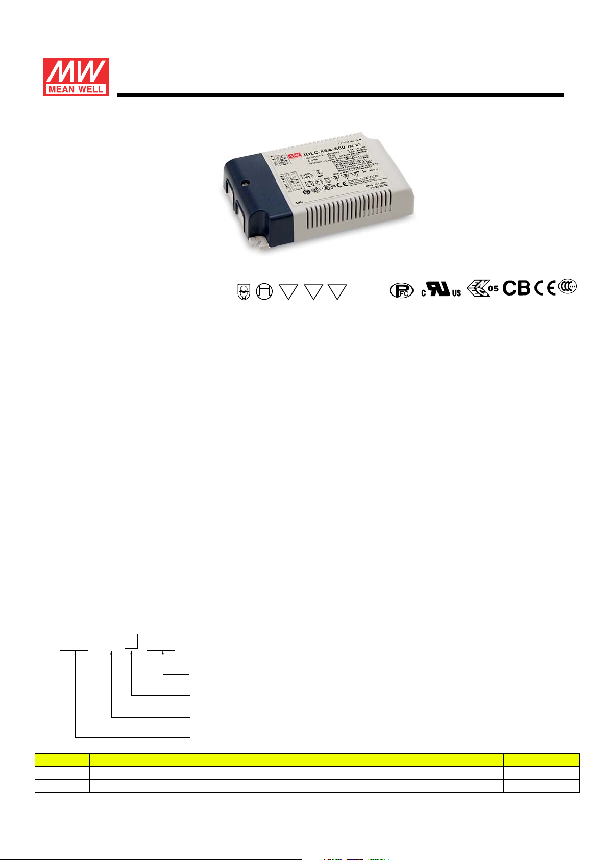
45W Constant Current Mode LED Driver
IDLC-45 series
FMM
SELV
■ Features ■ Applications
Constant Current mode output
Flicker free design
Plastic housing with class II design
LED panel lighting
LED flood lighting
Indoor LED lighting
Built-in active PFC function
No load power consumption<0.5W(Blank-Type)
Function options: 2 in 1 dimming (dim-to-off);
Auxiliary DC output
3 years warranty
■ Description
IDLC-45 series is a 45W LED AC/DC driver featuring the constant current mode output with flicker
free design.IDLC-45 operates from 90~295VAC and offers models with different rated current
ranging between 350mA and 1400mA. Thanks to the efficiency up to 86%, with the fanless design,
the entire series is able to operate for -20 ~+85 case temperature under free air convection.℃℃
IDLC-45 is equipped with various function options, such as dimming methodologies, so as to
provide the optimal design flexibility for lighting system.
■ Model Encoding
-
IDLC
Type
Blank
A
45
-
2 in 1 dimming (0~10VDC and 10V PWM)
2 in 1 dimming
A
500
Rated output current(350/500/700/1050/1400mA)
Function options
Rated wattage
Series name
Function Note
and Auxiliary DC output
In Stock
In Stock
File Name:IDLC-45-SPEC 2016-06-16
Page 2
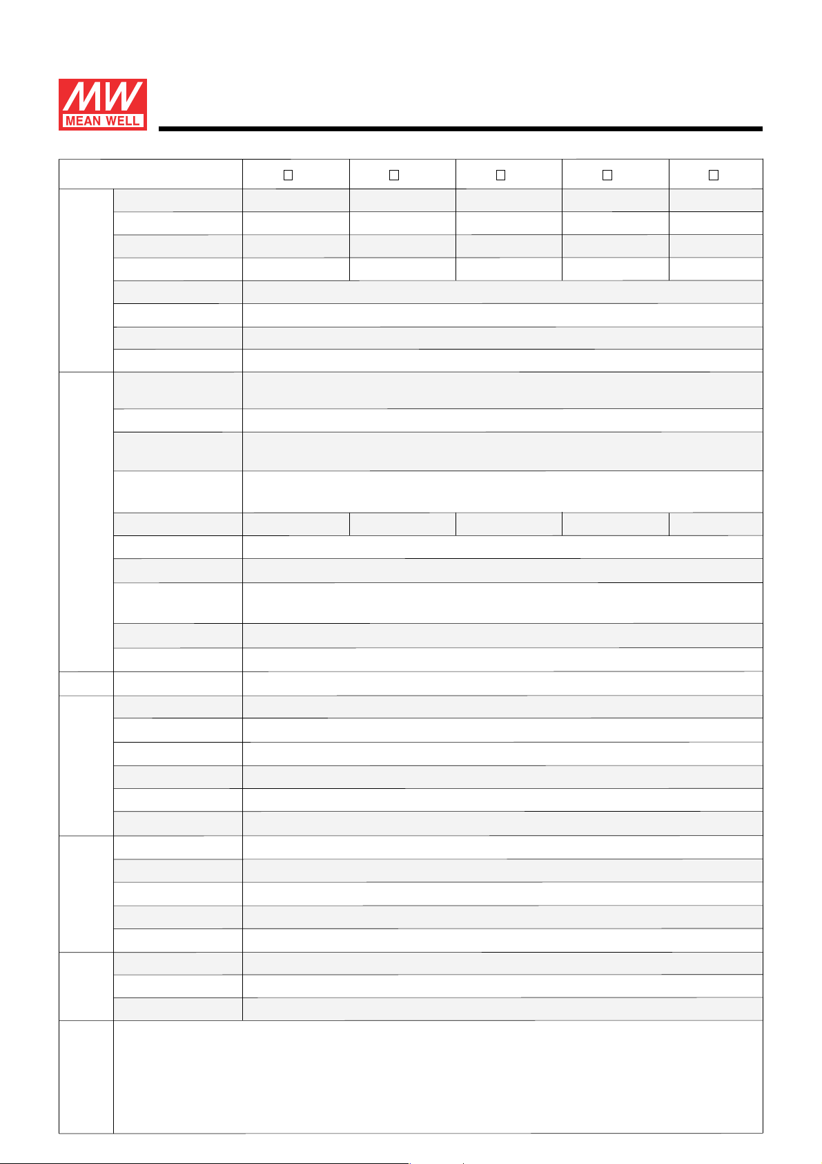
SPECIFICATION
45W Constant Current Mode LED Driver
IDLC-45 series
MODEL
OUTPUT
INPUT
RATED CURRENT
RATED POWER
CONSTANT CURRENT REGION
OPEN CIRCUIT VOLTAGE
Note.2
(max.)
CURRENT RIPPLE
CURRENT TOLERANCE
SETUP TIME
AUXILIARY DC OUTPUT
Note.4
Note.5
VO LTAGE RA NGE Note.3
FREQUENCY RANGE
POWER FACTOR
(Typ.)
TOTALHARMONIC DISTORTION
EFFICIENCY (Typ.)
AC CURRENT
INRUSH CURRENT
(Typ.)
IDLC-45 -350
350mA
33.25W
57 ~ 95V
118V
IDLC-45 -500
500mA
45W
54 ~ 90V
115V
IDLC-45 -700
700mA
44.8W
38 ~ 64V 19 ~ 32V
84V
IDLC-45 -1050
1050mA
45.15W
26 ~ 43V
63V
5% max. @rated current
±7.0%
500ms / 230VAC 1200ms/115VAC
Nominal 12V(deviation 11.4~12.6)@50mA forA-Type only
90 ~ 295VAC 127 ~ 417VDC
(Please refer to "STATIC CHARACTERISTIC" section)
47 ~ 63Hz
PF>0.95/115VAC, PF>0.92/230VAC, PF>0.9/277VAC@full load
(Please refer to "POWER FACTOR (PF) CHARACTERISTIC" section)
THD< 20%(@load 60%/115VAC,230VAC; @load 75%/277VAC)≧≧
(Please refer to “TOTAL HARMONIC DISTORTION” section)
86%
85%
85% 83%
84%
0.6A/115VAC 0.4A/230VAC 0.3A/277VAC
COLD START 30A(twidth= s measured at 50% Ipeak) at 230VAC100μ;Per NEMA 410
IDLC-45 -1400
1400mA
44.8W
50V
MAX. No. of PSUs on 16A
CIRCUIT BREAKER
LEAKAGE CURRENT
NO LOAD POWER CONSUMPTION
PROTECTION
SHORT CIRCUIT
WORKING TEMP.
MAX. CASE TEMP.
WORKING HUMIDITY
ENVIRONMENT
STORAGE TEMP., HUMIDITY
TEMP. COEFFICIENT
VIBRATION
SAFETY STANDARDS
WITHSTAND VOLTAGE
SAFETY &
EMC
ISOLATION RESISTANCE
EMC EMISSION
EMC IMMUNITY
MTBF
OTHERS
DIMENSION
PACKING
NOTE
1. All parameters NOT specially mentioned are measured at 230VAC input, rated current and 25 of ambient temperature.℃
2. Please refer to "DRIVING METHODS OF LED MODULE".
3. De rating may be needed under low input voltages. Please .- refer to STATIC CHARACTERISTIC sections for details
4. Length of set up time is measured at cold first start. Turning ON/OFF the driver may lead to increase of the set up time.
5. There is no design of short circuit protection for the Auxiliary DC output; this function can not be used when dimming input terminals(DIM+,DIM-)
6. The driver is considered as a component that will be operated in combination with final equipment. Since EMC performance will be
32 units (circuit breaker of type B) / 32 units (circuit breaker of type C) at 230VAC
<0.75mA / 277VAC
<0.5W for Blank-Type, <1.2W for A-Type
Hiccup mode, recovers automatically after fault condition is removed
Tcase=-20 ~ +85 (Please refer to “ OUTPUT LOAD vs TEMPERATURE” section)℃
Tcase=+85℃
20 ~ 90% RH non-condensing
-40 ~ +80 , 10 ~ 95% RH℃
±℃ ℃0.03%/ (0 ~ 40 )
10 ~ 500Hz, 2G 10min./1cycle, period for 60min. each along X, Y, Z axes
UL8750,CSA C22.2 NO.250.13-12;ENEC EN61347-1 & EN61347-2-13 independent, EN62384,GB19510.1,GB19510.14 approved
I/P-O/P:3.75KVAC
I/P-O/P:100M Ohms / 500VDC / 25 / 70% RH℃
Compliance to EN55015, EN61000-3-2 Class C ( ) ; EN61000-3-3,GB17743,GB17625.1@load 60%≧
Compliance to EN61000-4-2,3,4,5,6,8,11; EN61547, light industry level( )surge immunity:Line-Line:1KV
408.8Khrs min. MIL-HDBK-217F (25 )℃
120*75*25mm(L*W*H)
0.22Kg; 54pcs/ 13Kg/ 0.93CUFT
are short circuit or when it is no load or short circuit at output(Vo+,Vo-).
affected by the complete installation, the final equipment manufacturers must re-qualify EMC Directive on the complete installation again.
File Name:IDLC-45-SPEC 2016-06-16
Page 3
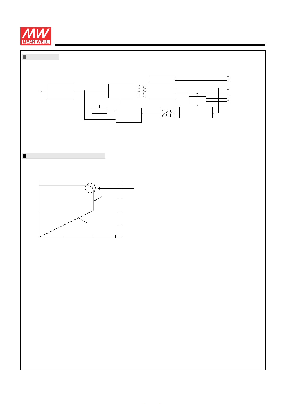
Block Diagram
45W Constant Current Mode LED Driver
IDLC-45 series
fosc : 70KH z
I/P
EMI FILTER
&
RECTIFIERS
O.L.P.
POWER
SWITCHING
PWM&PFC
CONTROL
DRIVING METHODS OF LED MODULE
※ This series works in constant current mode to directly drive the LEDs.
100
Constant
Vo(%)
60
(min.)
Current area
Hiccup
Protection
RECTIFIERS
RECTIFIERS
&
FILTER
CURRENT
LIMIT
DETECTION
CIRCUIT
AUX+(for A-Type)
AUX-(for A-Type)
Vo+
Vo-
DIM+
DIM-
In the constant current region, the highest voltage at the output of the driver
depends on the configuration of the end systems.
Should there be any compatibility issues, please contact MEAN WELL.
50
100
Io(%)
Typical output current normalized by rated current (%)
File Name:IDLC-45-SPEC 2016-06-16
Page 4
45W Constant Current Mode LED Driver
IDLC-45 series
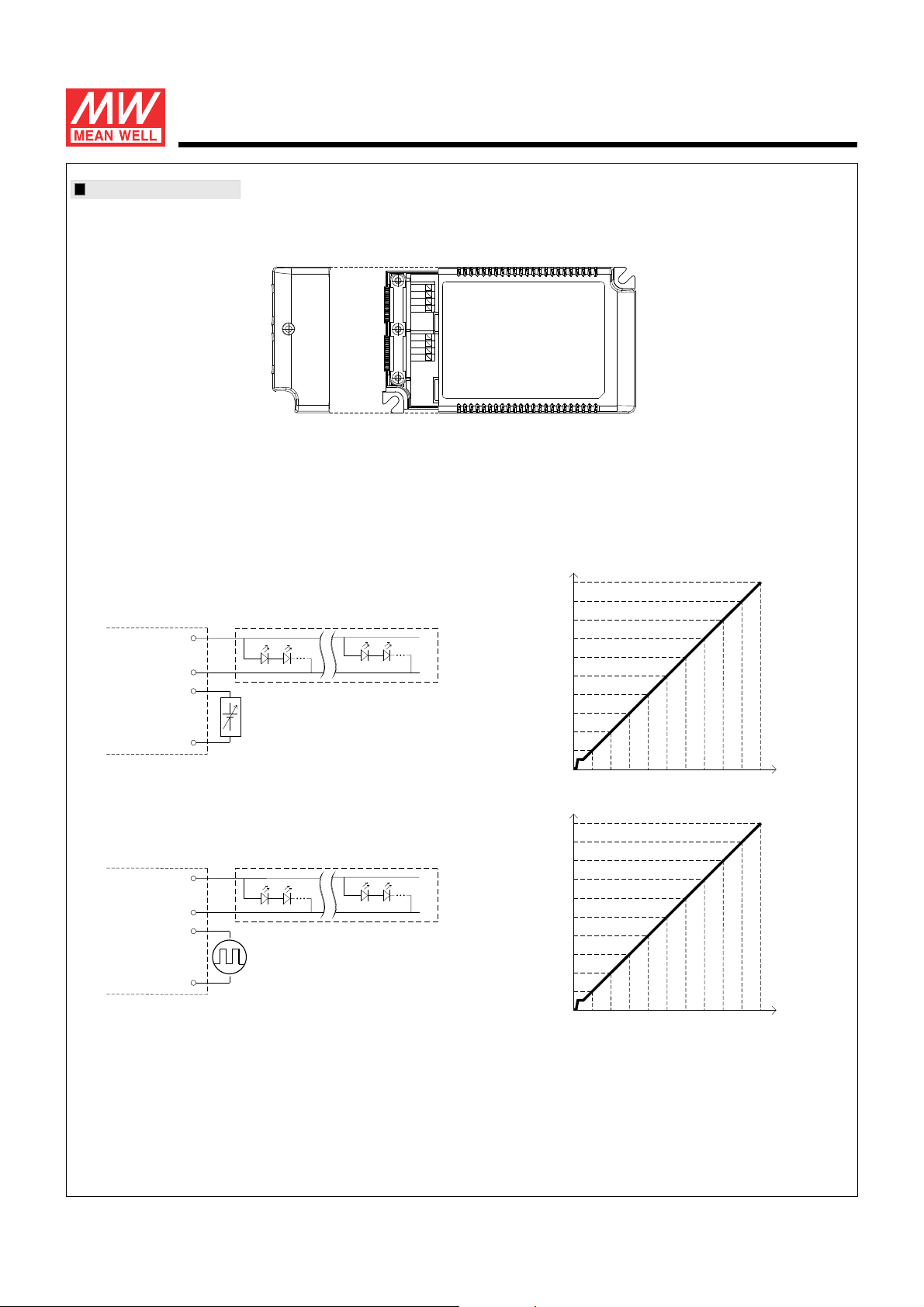
DIMMING OPERATION
※ 2 in 1 dimming function
ACL
ACL
TB1
ACN
ACN
DIM+
DIM-
TB2
Vo+
Vo-
Output constant current level can be adjusted by applying one of the two methodologies between DIM+ and DIM-:
0 ~ 10VDC, or 10V PWM signal.
Direct connecting to LEDs is suggested. It is not suitable to be used with additional drivers.
◎ Applying additive 0 ~ 10VDC
+
Vo+
-
Vo-
DIM+
DIM-
“DO NOT connect "DIM- ”to Vo-
+
Additive Voltage
-
+
-
◎ Applying additive 10V PWM signal (frequency range 300Hz ~ 3KHz):
+
Vo+
-
Vo-
DIM+
DIM-
“DO NOT connect "DIM- ”to Vo-
Additive PWM signal
+
-
100%
90%
80%
70%
60%
50%
40%
Output current (%)
30%
20%
10%
0%
0V 1V 2V 3V 4V 5V 6V 7V 8V 9V 10V
Dimming input:Additive voltage
100%
90%
80%
70%
60%
50%
40%
Output current (%)
30%
20%
10%
0%
0%
10% 20% 30% 40% 50% 60% 70% 80% 90% 100%
Duty cycle of additive 10V PWM signal dimming input
Note : 1. Min. dimming level is about 8% and the output current is not defined when 0%< out<8%.I
2. The output current could drop down to 0% when dimming input is about 0Vdc or 10V PWM signal with 0% duty cycle.
File Name:IDLC-45-SPEC 2016-06-16
Page 5
0.7
0.75
0.8
0.85
0.9
0.95
1
50% 60% 70% 80% 90% 100%
115V
230V
277V
76
78
80
82
84
86
88
90
50% 60% 70% 80% 90% 100%
277V
230V
115V
0
2
4
6
8
10
12
14
16
50% 60% 70% 80% 90% 100%
277V
230V
115V
45W Constant Current Mode LED Driver
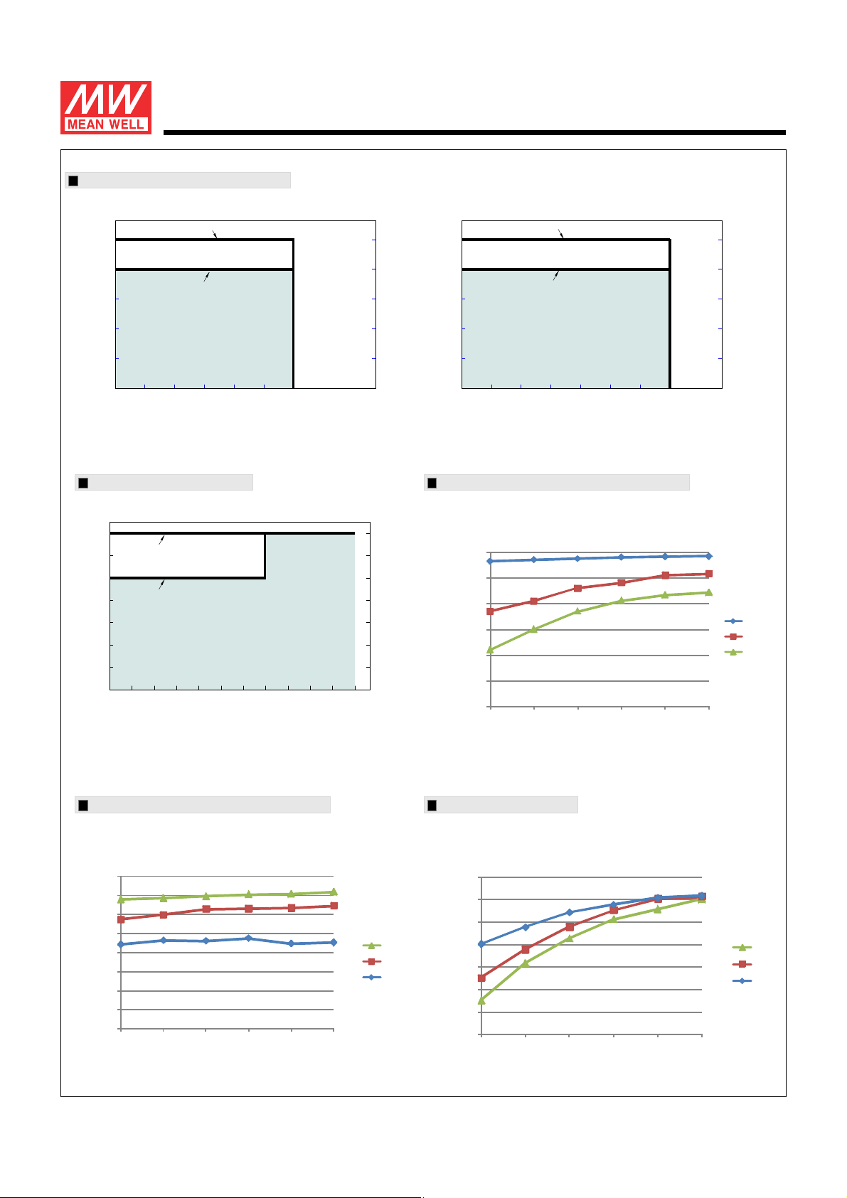
OUTPUT LOAD vs TEMPERATURE
IDLC-45 series
90~295VAC for 350mA Model,200~295VAC for others
100
80
90~200VAC for models other
60
than 350mA Model
40
LOAD (%)
20
-20 -10 0 10 20 30 40
AMBIENT TEMPERATURE,Ta ( )℃
STATIC CHARACTERISTIC
100
for 350mA Model
90
80
for others
70
60
50
LOAD (%)
40
(HORIZONTAL)
90~295VAC for 350mA Model,200~295VAC for others
100
80
90~200VAC for models other
60
than 350mA Model
40
LOAD (%)
20
-20-100 1530456085
Tcase ( )℃
POWER FACTOR (PF) CHARACTERISTIC
※ Tcase at 75℃
PF
(HORIZONTAL)
90 295
135 180
INPUT VOLTAGE (V)
※De-rating is needed under low input voltage.
TOTAL HARMONIC DISTORTION (THD)
※ 350mAModel,Tcase at 75℃
THD(%)
LOAD
200
(45W)
LOAD
EFFICIENCY vs LOAD
IDLC-45 series possess superior working efficiency that up to 86% can
be reached in field applications.
※ 350mAModel,Tcase at 75℃
EFFICIENCY(%)
LOAD
File Name:IDLC-45-SPEC 2016-06-16
Page 6
45W Constant Current Mode LED Driver
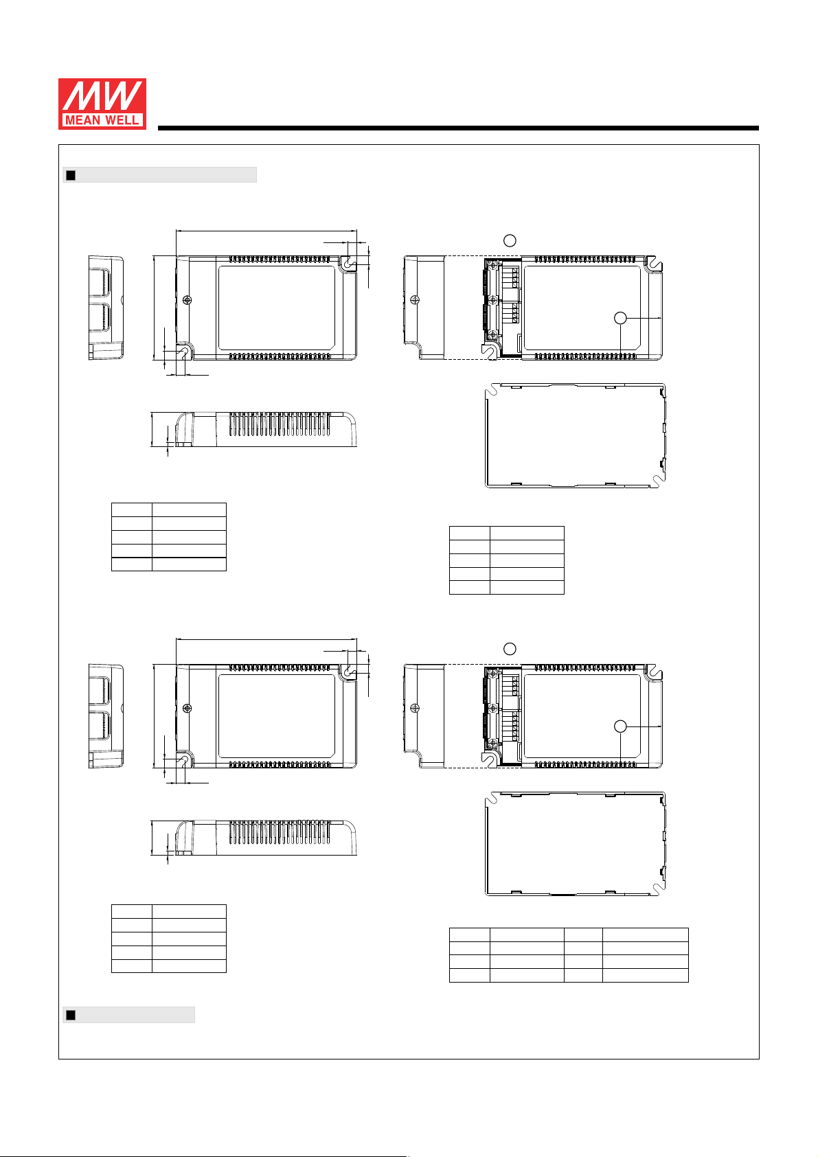
MECHANICAL SPECIFICATION
※ Blank-Type
IDLC-45 series
Case No.IDLC-45A Unit:mm
75
6.5
3
25
Terminal Pin No.Assignment(TB1)
Pin N o.
Assignment
1
2
3
4
ACL
ACL
ACN
ACN
※ A-Type
120
6.5
6.5
6.5
tc
: Max. Case Temperature
1
2
TB1
3
4
1
2
TB2
3
4
tc
30
30
Terminal Pin No.Assignment(TB2)
Pin No.
120
6.5
Assignment
1
2
3
4
DIM+
DIM-
Vo+
Vo-
tc
: Max. Case Temperature
6.5
75
6.5
6.5
3
25
Terminal Pin No.Assignment(TB1)
Pin N o.
Assignment
1
2
3
4
ACL
ACL
ACN
ACN
Installation Manual
Please refer to : http://www.meanwell.com/webnet/search/InstallationSearch.html
1
2
TB1
3
4
1
2
3
TB2
4
5
6
Terminal Pin No.Assignment(TB2)
Pin No. Pin No.
Assignment Assignment
1
2
3
DIM+ VoDIM-
Vo+
4
5
6
30
tc
30
AUX+
AUX-
File Name:IDLC-45-SPEC 2016-06-16
 Loading...