

Page 1
GC330
Instruction Manual
Page 2
GC33 0 Instruction Manual
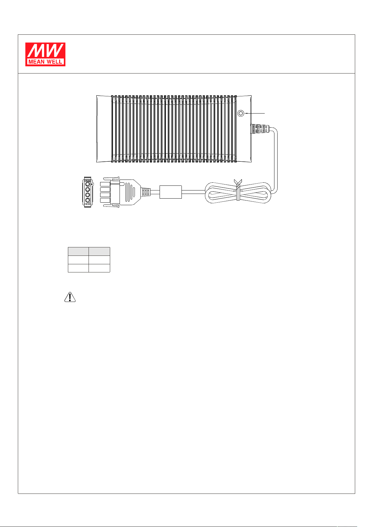
POWER LED
1
2
3
4
UL2464 16AWGx4C 1000 50mm±
Standard mal e plug( power s up ply sid e): AMP 1- 480702- 0 equivalent
PIN NO.
Femal e plu g( custome r side, n ot pr ov ide wit h the p ower su pp ly): AMP 1-48 0703-0 equival ent
Assembly Proced ure
1.Ma ke sure th e c harg er is sh ut off and c ho osin g suitable wi re s to co nnect th e ch arger an d bat te ri es based on the r ating o f c ha rg in g
current. The pol ar ity must be corre ct: charger output (+ ) sho uld be conne cted to the ( +) te rm inal of batteries an d charger ou tput (-)
shou ld be conn e cted to the ( -) te rm in al.
In no ti me s shoul d the (+) an d (- ) b e shor t t oget her or th e charger and bat teries will b e da ma ged.
2.Co nnect the AC input and che ck wh et her the op erat io n o f LE D is corr ect.
(red : cha rg in g ; gr een : battery is f ull)
Note s On Operat ion:
1.The cha rg er should be as se mbled in th e pla ce wi th go od ve ntilatio n and low m oisture.
Exposure to the r ain o r snow is st ri ctly pr ohibited.
2.Wir es co n necti n g be tw een t he charger a nd ba tterie s should be as shor t as po ss ib le s i nce t he high vo lt ag e dro p on th e wire s will
in cr ea se the t im e r equi red to f ul ly char ge the b atteries.
3.Ma ke sure th e c harg in g volta ge an d c har ging current ar e sui table for the batte ri es yo u a re us ing.
4.If th e batt e ri es n eed to conn ec t in s eries for c ha rging , old ba tteries are not sugges ted t o be use d w ith ne w ones or th e lifetime of
batter ie s may re duce because of th e unb alan ce charging vo ltage di stribu ti on on ne w a nd o l d batteries.
5.Plea se t u rn off the c ha rg er before conn ecting or di sconnect ing the w ir es .
6.The cha rg er ha s a 2- year wo rldwide warr anty, h owev er, damages from mi su sin g the charge r wi ll no t be inclu ded in t he coverage of
wa rr anty.
OUTPUT
1,2
3,4
+V
-V
WARNING :
:
Please make sure the polarity of the battery is connected correctly!
1
Page 3
Statu s Under Gen er al Op eration:
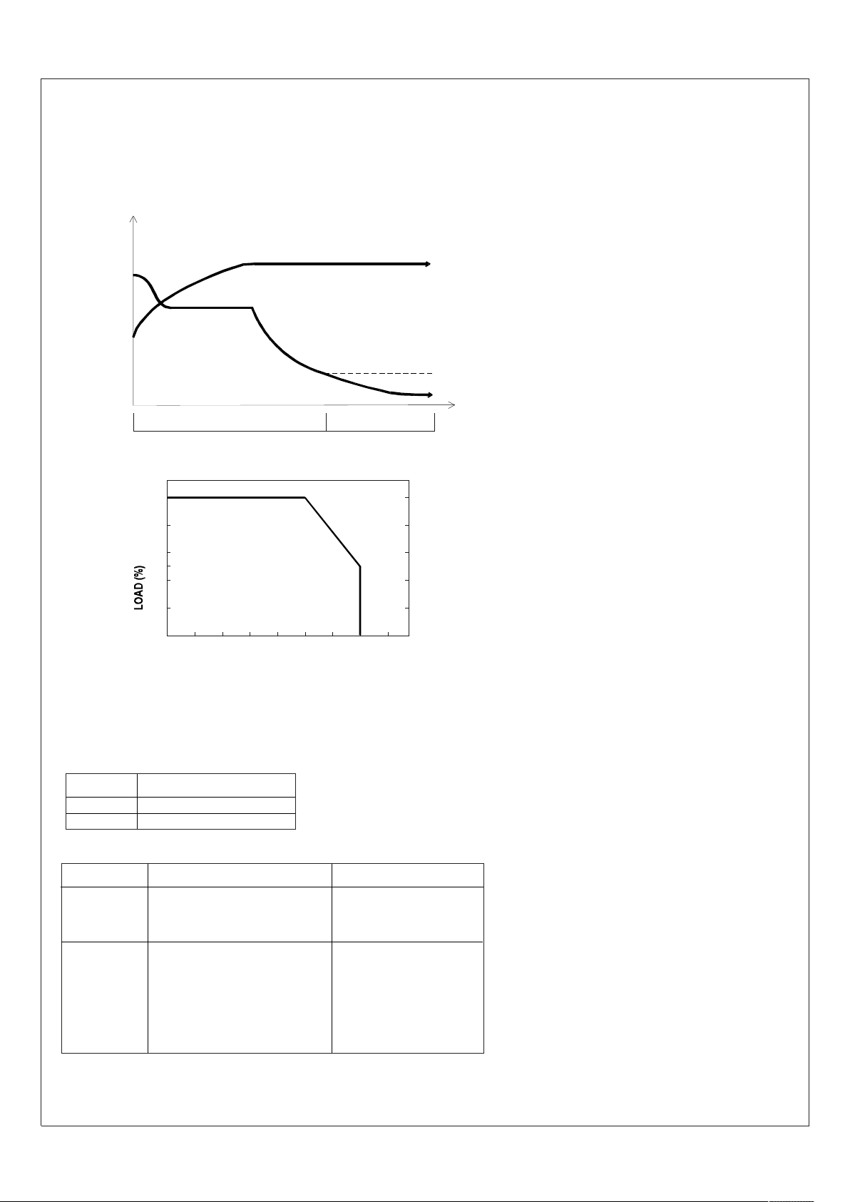
At t he begi n ning s tage of oper atio n, the cha rger provides the l arge st cu rr ent with 40.8Vdc of outp ut voltag e (for 36V b atteries) to
charg e ba tt er ie s. The LED indi cator w ill lig ht en in red. After a period of tim e (pro bably a co up le of ho urs, based on t he ca pacity of
batte rie s), the chargi ng curr en t w ill d ec re ase gra dual ly. After reachi ng of i ts maximum v alue, t he ch arge r w il l go into
0.3A 0.1A±
"float ing-ch ar ge" s tage. The L ED ind i cator will tur n to green. The r elat ions hip bet we en char g ing current a nd chargi ng volt age f or each
opera t ion s tage ar e sho wn in t he cur ves be low :
(V,I)
Sta ge 1
Con st ant Curren t Are a
Sta ge 2
Const ant Voltage Area
V
Fast Chargin g
0.3A 0. 1A±
Colo r of LE D
Fl oat C harg ing
Red Gre en
I
TIM E
Ch argi n g Curr ent And Ambient Temp e rat ure
100
80
60
50
40
20
0-3 0 2010 30 40
6050 7 0
(HOR IZONTAL)
EXTERNAL CASE TEMP ERATURE ( )℃
Su gges ted Battery Capac ity:
1.I t will n ot hav e any problem if t he capacity of batteri es large r tha n the suggested v alue. It j us t takes mo re time t o ma ke the batteries
fully c harge d!
2. If you h ave a ny que s tion about t he suitabl e c h arging cur r en t for the batter ie s , plea se refer to the tec h nical d at a pr ovid ed b y th e
batte ry ma nufactu re rs o r c ons ult the ven do r of th e ba tter ie s.
Mod e l
Sug geste d Batt e ry capa city
GC33 0A 36 20 -65Ah
GC33 0A 48 20 -65Ah
Notes On Failu re Elimination
St at us
No ou tp u t
vo ltage
Possible Re as ons
Wrong po larity o f the b attery
conn ect ion
Wa ys to El iminate
Repair requi red. Pl ea se
send it back to u s or any
of our distribu tors
Ca n't achie ve
the FLOAT
(green ligh t)
stage aft er
Repla c e the bat teriesBa tt eries are a ging or brok e n
lo ng pe riod
of ch ar gi ng
op erat io n
If yo u still cannot elim inate the failure s itu ation, please consult
MEAN WELL or any o f our distributors
2
Page 4

IMPO RTANT SAF ETY INS TR UC TI ONS - SAVE THESE IN ST RU CT IONS
DANGER
1.Thi s ma nu al co nt ains importa nt sa fety an d o pe rati ng inst ru ctions f or ba tter y c ha rger Mode ls GC2 20A12 ,G C2 20A2 4 a nd GC220A48.
2. - Mode ls
SAVE TH ES E IN S TRUC TI ON S Th is ma nual contain s impo rtant s af ety a nd op erat in g Instr uctions for battery ch ar ge r
GC 330A 36 and G C3 30A4 8.
3.Before us in g batte ry char ge r, r ea d all instruct io ns an d cauti onary marking s on batter y char ge r, batte ry, an d pro duct usin g batte ry.
4.CAUTIO N
series, for Mode l G C3 30 A36; char ge only four, 12V L ead-Acid type rech argeab le ba tter ie s, whic h w er e c on ne cted in seri e s, f or
Mo de l GC3 30A48.
5.Power Su pply Cord:
Power Su pply Co rd - C ord Type SJ T or SVT, ra ted m in imum 10 5 , N o. 18AWG/ 3C,pro vi de d with a mold ed -o n, grounding t ype
atta ch me nt pl ug wi th a 1 5A, 125V( NEMA 5-15p ) conf ig urati on and a mol ded-on conn ec tor w hich mates w ith th e appl ianc e inl et,
mini mu m 1.8 m and m aximum 3 m in lengt h.
6.
The equip ment wa s i nves ti gate d u nder 20 ampe res b ra nc h c ir cuit in acco rdan ce wi th the Nati onal Electric al Code, ANSI/N FPA 70, t o
redu ce th e r is k of fire, connec t only a circ uit provi ded with 20 ampere s m axim um branch over cu rr ent p ro tect io n.
- TO REDUCE TH E R IS K OF FIRE OR ELECT RIC SHOC K.
CAR EFUL LY FOLLOW THESE INSTR UCTIO NS.
-
To red uce risk of in ju ry, cha rge on ly one, 12 V L ead-Ac id ty pe rechar gea b le ba tter ies , whic h were connected in
℃
3
 Loading...