

Page 1

Instruction Manual
Model 20BO
B" Schmidt -Cassegrain
Model 2120
10" Schmid~ -- Cassegrain
Page 2

CONTENTS
Introduction 5
The Basic Model 2080 Telescope: Standard Equipment 5
The Basic Model 2120 Telescope: Standard Equipment 6
Setting Up the Model 2080 6
Assembly and Set-up of the Model 2120 8
Telescope Op~ration: Your First Observations 10
Focusing 12
Magnifications 12
Viewfinder: Model 2080 15
Viewfinder: Model 2120 16
Field Tripod 17
Equatorial Wedge 20
Mounting the Telescope onto the Wedge 23
Celestial Coordinates 24
Lining Up with the Celestial Pole 25
Precise Polar Alignment . 28
Polar Alignment at Low Latitudes 30
Electric Motor Drive 30
Setting Circles _ 31
Observing with the Telescope 32
Optional Accessories and Systems
Eyepieces (l~flO.D.) 34
Eyepieces (2" O.D.) 34
Barlow Lenses 34
2" Diagonal Mirror 35
Thread-in Color Filters 35
Series -6 Color Filters 37
Erecting Prism 39
8 x 50mm Right-Angle Viewfinder for Model~ 2080 39
Nebular Filters 39
Solar Filters 40
Wide-Field Adapter System (WFAS) 41
Dew Shield 41
Accessory Shelf 42
Altazimuth Adapter 42
Photographic Accessories
T-Adapter 44
Tele-Extender 47
Guided Astrophotography 48
Piggyback Camera Bracket 49
Off-Axis Guider 50
Telecompressor- 51
Tube Balance Weight System 52
Cleaning the Optics 52
Alignment (Collimation) of the Optical System 54
Dewing of the Correcting Plate 56
Adjusting the Right-Ascension Lock 57
Adjusting the Declination Lock 57
A Note on the "Flashlight" Test 58
Factory Servicing and Repairs 58
Basic Specifications: Model 2080 58
Basic Specifications: Model 2120 60
Optical Reference Information 61
Page 3
NOTE
Instructions for the use of the following optional
accessories and systems are not included in this
manual, but are shipped with the respective items:
Table Tripod for Model 2080
Model 46 VariGuide Dual-Axis Drive Corrector
Models 2047, 2048 4" Schmidt-Cassegrain Photo-Guide
Telescopes
Models 2066, 2068 4" f/2.64 Schmidt Cameras
Models 41 and 43 R.A. Drive Correctors
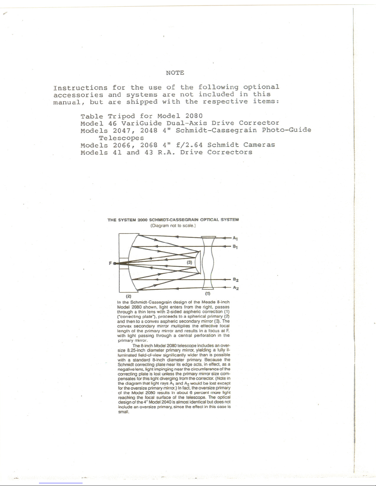
THE SYSTEM 2000 SCHMIm:cASSEGAAlN OPTICAL SYSTEM
(Diagram not to scale.)
F
(2)
In the Schmidt-Cassegrain design of the Meade &-inch
Model 2080 shown. tight enters from the right. passes
through a thin lens with 2-stded aspheric correction (1)
rcorrecting plate1. proceeds to a spherical primary (2)
and then to a convex aspheric secondary mirror (3). The
convex secondary mirror multiplies the effective focal
length of the primary mirror and results in a focus at F.
with light passing through a central perforation in the
primary mirror.
The 8-inch Mode12080 telescope includes an over-
size 8.25-inch diameter primary mirror. yielding a fulty it.
luminated fieId-of-view significantly wider than is possible
with a standard 8-inch diameter primary. Because the
Schmidt correcting plate near its edge acts. in effect. as a
negative lens. ighI impinging near the circurnferenceof the
correcting plate is lost unless the primary mirror size c0m-
pensates for this light diverging from the corrector. (Note in
the diagram lhallight rays A1and A2would be lost except
for the oversize primary mirror.) In fact. the oversize primary
of the Model 2080 results in about 6 percent more &ght
reaching the focal surface of the telescope. The optical
design of the 4. Model 2040 is almost identical but does not
include an oversize primary. since the effect in this case is
small.
Page 4

-5-
MEADE MODELS 2080 and 2120
8" and 10" SCHMIDT-CASSEGRAIN TELESCOPES
PRECAUTIONARY WARNING! Be .sure to read this manual, or at
minimum the introductory assembly and operational proced-
ures contained herein (pages 5 to 15) before attempting to
use your Model 2080 or 2120.
INTRODUCTION
The Meade Model 2080 8" Schmidt-Cassegrain Telescope and
Model 2120 10" Schmidt-Cassegrain Telescope are.instruments
of advanced mirror-lens design for astronomical and terres-
trial applications. Optically and mechanically, the Models
2080 and 2120 are perhaps the most sophisticated and precisely-
manufactured telescopes ever made available to the serious
amateur. The Mode.ls 2080 and 2120 enable the visual astronomer
to reach out for detailed observations of the Solar System
(the planets: Jupiter, Saturn, Mars) and beyond to distant
nebulae, star clusters, galaxies. The astrophotographer will
find a virtually limitless range of possibilities since, with
the precision Meade worm-gear motor .drive system, long ex-
posure guided photography becomes not a distant goal, but
an achievable reality. The capabilities of the instrument
are essentially ~imited not by the telescope, but by the
acquired skills of the observer and photographer. Do take
the time to read this manual thoroughly, so that you will
be fully acquainted with the many important features of the
telescope, as well as with the auxiliary equipment arid
accessories.available for advanced applications.
The Models 2080 and 2120 are, with the exceptions of a few
assembly operations and features, almost identical operational-
ly. Most stapdard ~nd optional accessories are interchange-
able between the two telescopes. As such, the instructions
in this manual generally apply to both telesco~es; when ex-
ceptions to this rule occur, they are clearly pointed out in
the following.
THE BASIC MODEL 2080 TELESCOPE:
STANDARD EQUIPMENT
The Meade Model 2080 Telescope is packed in a urethane-foam-
lined carrying case.. If the telescope was shipped to you,
this carrying case was in turn placed in a thick-wall corru-
gated carton, lined on all 6 sides with styrofoam sheets.
(NOTE: We recommend that you keep all packing materials
for either the Model 2080 or Model 2120; if it is ever
;..:,-~.
Page 5
-6-
necessary for you to return your telescope to the Meade
factory for servicing, these materials will help to assure
that no shipping dam~ge will occur.)
Packed in the carrying case are the complete basic Model
20aO, consisting of the a" Schmidt-Cassegrain optical
tube assembly and fork mount. Accessories included as
standard equipment are normally also packed within the
carrying case.
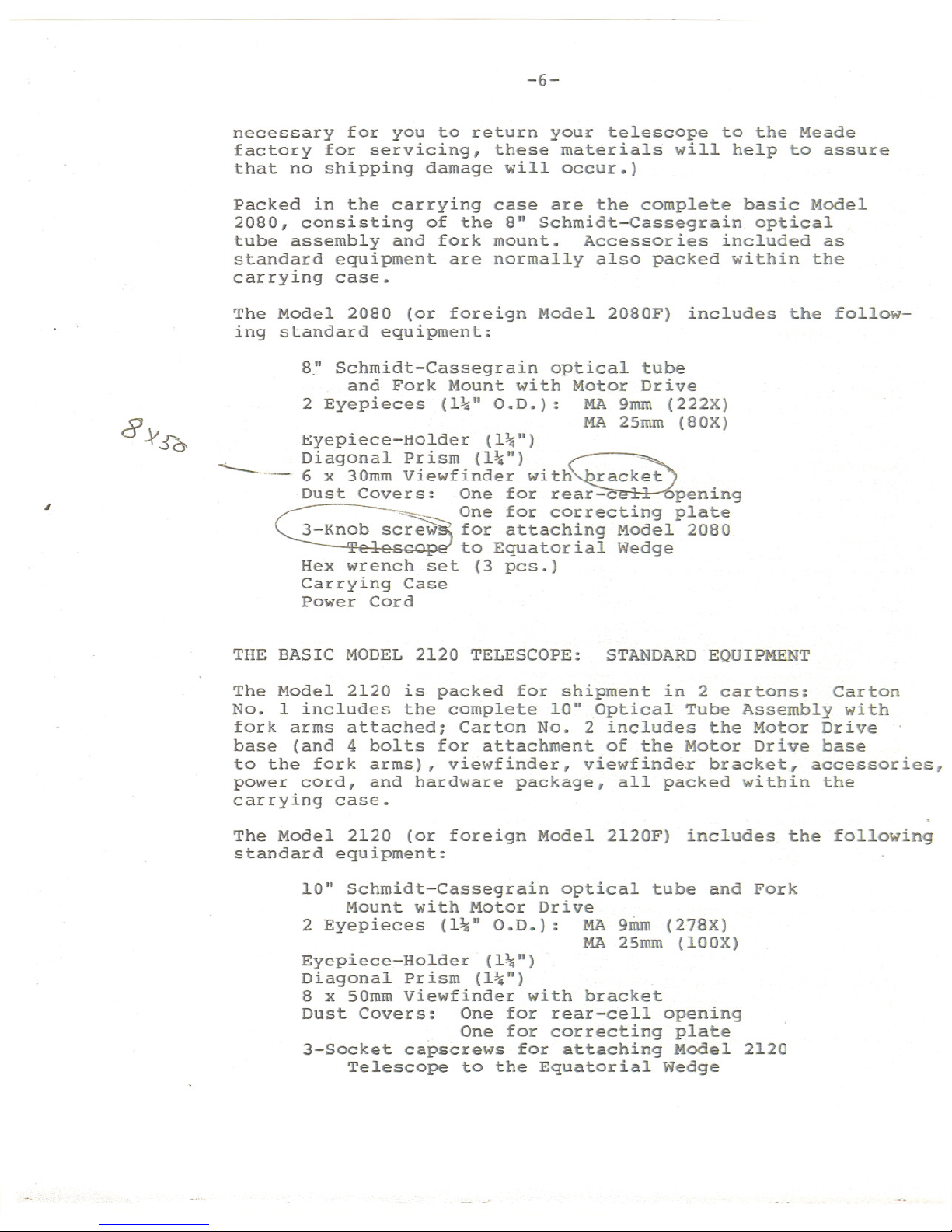
The Model 20aO (or foreign Model 20aOF) includes the follow-
ing standard equipment:
a."Schmidt-Cassegrain optical tube
and Fork Mount with Motor Drive
2 Eyepieces (l~" O.D.): MA 9mm (222X)
MA 25mm (aOX)
Eyepiece-Holder (l~'.)
. Diagonal Prism (1\,") ~ ~
6 x 30mm viewfinder witti rac~~t .
.Dust Covers: One for rear-c~ pen1ng
~ ~ One for correcting plate
3-Knob sc~ for attach~ng Model 2080
T to Equator1alWedge
Hex wrench set (3 pes.)
Carrying Case
Power Cord
THE BASIC MODEL 2120 TELESCOPE: STANDARD EQUIPMENT
The Model 2120 is packed for shipment in 2 cartons: Carton
No. 1 includes the complete 10'. Optical Tube Assembly with
fork arms attached; Carton No. 2 includes the Motor Drive
base (and 4 bolts for attachment of the Motor Drive base
to the fork arms), viewfinder, viewfindex bracket, accessories,
power cord, and hardware package, all packed within the
carrying case.
The Model 2120 (or foreign Model 2l20F) includes the following
standard equipment:
10" Schmidt-Cassegrain optical tube and Fork
Mount with Motor Drive
2 Eyepieces (l~" O.D.): MA 9mrn (27aX)
MA 2Smm (lOOX)
Eyepiece-Holder (l~n)
Diagonal pr ism (l~'.)
a x 50mm viewfinder with bracket
Dust Covers: One for rear-cell opening
One for correcting plate
3-Socket capscrews for attaching Model 2120
Telescope to the Equatorial Wedge
Page 6

-7-
Fig. 1: Meade Models 2080 and 2120. (1) Viewfinder;
(2) Declination Lock; (3) Declination Setting Circle;
(4) Declination Slow-Motion Control; (5) R.A. Lock;
(6) R.A. Slow-Motion Control; (7) Eyepiece-Holder;
(8) Diagonal Prism; (9) Eyepiece; (10) Focus Knob;
(II) Drive Base; (12) R.A. Setting Circle.
Page 7

-8-
Hex wrench set (5 pes.)
Carrying -C~se
Power Cord
- -
- .
Note to For.eignUsers:'S" and 10" Schmidt-Cassegrain...models
supplied to countries' ou'tside-thet,J.S.A.;: -are
identical in
all respects.to the telescopes offered domestically,-except
that the powe.rcord and-the'electrica1'connector (located
in the base 'ofthe.telescope fork mount) are different. The
power cord'plugs directly into th~ base of the .telescope
. (see "The Motor Drive"), but you -'may-have to s1ipply your own
adapter in order-.-to 'plug into your loca.l. electric~l outlet.
In this case be sure that the adapter is of a "3-prong" type
so that the .telescope is'proper ly .grounded'a-t. all times
during operation. .-
SETTING UP THE-MODEL 2080
The basic-Model 2080. telescope is shipped as a completely
assembled ins.trument
~ -For safety in shipment the 6 x 30mm
Viewfinder is_ packed separately. (See "The Viewfinder,."
below.) After removing the telescope from j,ts shipping
carton and carrying case, famili~rize yourself with the
various control~,and accessories; see Fig. .1.
The eyepiece-holder threads directly onto the rear-cell
thread of the Models 20S0 and 2120. The diagonal prism slides
into the eyepiece-holder and in turn accepts either of the
supplied l~" O.D. eyepieces. For astronomica-l observations
the diagonal prism generally provides a more comfortable
right-angle viewing position. Alternately, an' eyepiece may
be inserted directly into the Eyepiece-Holder for straight-
through observations.- Note in this case, however, that
the image will app~a'r inverted and reversed left-for-right.
with the Diagonal Prism, telescopic images appear correctly
oriented up-and-down, but still reversed left-for-right. For
terrestrial applications,: where a,fullycorrected image
orientation is desired,'-both up-and-down and left-for-right,
the optional =1924 Erecting Prism :(l~"O.D.) should be ordered
separately._ (See the Meade General' Catalog for
details.)
Eyepieces and the Diagonal Prism are held in their respec-
tive places on- the telescope by a.moderate tightening of the
thumb-screws on the Diagonal Prism and Eyepiece-Holder.
ASSEMBLY AND SET-UP OF THE MODEL 2120
The basic Model 2120 telescope is shipped with the optical
tube assembly (with fork ar~s attached) in one carton,
and with the motor drive base in a separate carton. The
only assembly operations required are the following:
Page 8

-9-
1. Attaching the fork arms to the motor drive base.
2. Attaching the viewfinder and viewfinder bracket
to the optical tube.
'. :
To -remove-the optical tube-from the shipping carton, (1) lift
off the lid of the carton; (2) place the carton on end with
the eyepiece-end- at the bottom; (3) remove packing material
from the top of the carton; (4) pull the tube assembly
toward you and out-of the carton.
To attach the fork arms'to the motor drive base: (1) Place
the optical tube flat on a carpeted- floor. (2) Remove
the threaded metal rod that has been used to tie the fork
arms-together for safety in shipment (this rod may be set
as.idefor re-use;
-in case of future commercial shipment).
:(3) Remove the, 4 bolts (2 on. each side) from ~he flat
sides of the motor d~ive base (these bolts will be used to
attach"the fork arms to the drive base). . (4) Note that the
flat surfaces at the bottoms of the fork arms are numbered;
these~numbers will aid you in joining the correct.fork arm
to the -correct side of the drive base. Thus, join the No. 1
fork_'arm to.the No. I-side of the drive base, and the No.2
'fOrk arm to the No.2-side of the drive base. (5) Thr~ad
-in:,by hand the 4 attachingbolts (2 througheach fork arm)
through'the fork arms and into the drive base, to get the
bolts,well started. Then use the long-arm of the hex wrench
,pr.ovided,to screw in the bolts the rest of the way. For
final tightening use the short arm of the hex wrench. These
bolts should be tightened to a good firm tightness. Once
attached, the fork arms may be left permanently attached to
the drive base and the complete optical tube/fork mount/drive
base system may be stored as an assembled unit in the carry-
ing case. '(The only exception to this statement is in"ship-
ment of the telescope by commercial freight carrier, in
which case the drive base should be removed, and the telescope
shipped exactly in the'manner in which you received it.)
To store.your telescope in its carrying case you may find the
following procedure most convenient:
1. Stand the case on end with the lid open.
2. Place -the telescope inside the case wi:ththe
flat side of the drive base at bottom.
3. If the 8 x 50 viewfinder (see liTheViewfin~er:
Model 2120", below.) is mounted on the tele-
s90pe you will note that it will prohibit your
closing the lid of the case. Therefore,
'4. Push the fork arm on the side of the viewfinder
towards the back (or bottom) of the case. You
will note that the viewfinder is now far enough
back so that the-lid, when closed, will not touch
the viewfinder.
Page 9

- ----
-- --
-10-
5. Tuck in the 2 pieces gf blue foam (provided with
shipment) along .the base of each fork arm so that
the instrument will not move inside the case. You
can now store the instrument or place it in your
car for transport to an observing site.
CAUTION
DO'NOT ATTEMPT TO TURN THE FOCUSER KNOB OF THE OPTICAL TUBE
UNTIL YOU HAVE READ THIS NOTICE!
Next to the base of the focuse~ knob you will see a red-
colored slotted bolt head. This bolt is used only for safety
in shipment. Remove this bolt before attempting to turn the
focuser knob. In-its place insert the rubber plug provided
as a dust protector (this rubber plug is included with your
hardware package).
Your.focuser is now operational.
WARNING! The Mode~ 2120 should never be commercially shipped
without this red~colored-head bolt secured in place. .This is
essential during commercial transport where rough handling
may occur. For your:personal transport and storage you will
never need to use this bolt again.
TO COMMERCIALLY RE-SHIP THE MODEL 2120 BE SURE TO FOLLOW
THIS PROCEDURE:
1. Turn the focuser knob clockwise continuously
until.it stops. This will bring the primary
mirror all.the way back in the tube.
2. Remove the rubber plug and insert the red-headed
bolt. Thread it in to a firm snug feel.~ Do not
over-tighten. (If you have misplaced the 'red-
head bolt you may use any other bolt that is
~-20xl" long).
Please note that commercial shipment of the Model 2120 tele-
scope without this safety bolt in place is done at owner IS
risk and your freight insurance may be voided if shipping
damage results.
TELESCOPE OPERATION:
MODEL 2080 OR 2120
!
YOUR FIRST OBSERVATIONS THROUGH THE
with the telescope standing upright on its motor drive
base, as shown in -Fig. 1, and with the Diagonal Prism/and
MA 25mm eyepiece in place, you are ready to make observations
through the telescope. (Because the viewfinder has not yet
been attached to the telescope, be sure to use the MA 25mm
eyepiece, which yields 80 power on the Model 2080 (IOOX on
the Model 2120), and not the higher power MA 9mm eyepiece.
Page 10

-11-
Even without the-viewfinder, terrestrial objects will be
fairly easy to locate and center in the telescope's field
of view with the lower-power eyepiece, simply by "gun-
sighting" along the side of the main telescope tube.)
IMPORTANT NOTE: NEVER POINT THE TELESCOPE DIRECTLY AT THE
SUN, OR ATTEMPT TO OBSERVE.THE SUN, EITHER THROUGH THE
MAIN TELESCOPE.OR THE VIEWFINDER, WITHOUT PROPER PROFESSION-
AL EQUIPMENT. INSTANT AND IRREVERSIBLEDAMAGE TO YOUR EYE
MAY OTHERWISE RESULT! (SEE "SOLAR FILTERS" IN THIS MANUAL.)
By unlocking the.R.A. lock (5), Fig. 1, the te"lescope
may
be turned rapidly through wide angles in Right Ascension
(R.A.). (The reason for the terminology."Right Ascension"
and its complementary term "Declination" will be made clear
further on in this manual. For now, "Right Ascension" I
simply means "h.orizontal" and "Declination" means "vertical.")
Fine-adjustmen.ts inR.A-. are made by turning the R.A. control
knob (6), Fig. 1, while the R.A. lock is in the "unlocked"
position.
DO NOT ATTEMPT TO MOVE THE TELESCOPE MANUALLY IN A HORIZONTAL
DIRECTION WHEN THE R.A. LOCK IS IN THE "LOCKED" POSITI'ON.
The R.A. control knob may be turned, if desired, with the
R.A. IO.ckin a "partially locked" position. In this way a
comfortable "drag" in R.A. is created. But do not attempt
to operate the R.A. control knob with the telescope fully
locked in R.A., as such operation may result in damage to
the internal gear system.
- Releasing the Declination lock (2), Fig. 1, permits sweep-
ingthe telescope rapidly through wide angles in Declination.
DO NOT ATTEMPT TO MOVE THE TELESCOPE.MANUALLY IN A VERTICAL
-DIRECTIONWHENTHE DECLINATION LOCK IS IN THE "LOCKED"
POSITION.
To use the Declination fine-adjust, or slow-motion, control,
lock the telescope in Declination using the Declination lock
(2), Fig. 1, and turn the Declination slow-motion knob (4).
NOTE THAT THIS DECLINATION SLOW-MOTION CONTROL HAS A F.IXED
TRAVEL LENGTH, LIMITED BY THE MOTION OF A TANGENT ARM
(LOCATED INSIDE THE FORK TINE). DO NOT FORCE THE DECLINATION
SLOW-MOTION KNOB
WHEN THE TANGENT ARM HAS REACHED THE END
OF ITS T.RAVEL. IN THIS CASE TURN THE DEC. KNOB TO RETURN THE
.TANGENT ARM TO THE MID-POINT IN ITS TRAVEL RANGE, UNLOCK
THE DECLINATION LOCK, AND RE-CENTER THE TELESCOPE TUBE MANUALLY.
With above mechanical .operations in mind, select an easy-to-
find terrestrial object as your first telescope subject--for
example, 'a house or building perhaps one-half mile distant.
Page 11

-12-
Unlock the Dec. lock (2), Fig. 1, and R.A. lock (5),
center the ~bject in the telescopic field of view, and then
re-lock the Dec. and R.A~ locks. Precise image centering is
accomplished by using the Dec. and R.A. slow motion controls,
(4 ) and ( 6) .
FOCUSING
The focusing knob (10), Fig. 1, is located at the "4 o'clock"
position as you face the rear cell of the telescope. Focus-
ing is accomplished internally by a precise motion of the
telescope primary mirror, so that, as you turn the focus knob
there are no externally moving parts.
Focusing the telescope from its nearest possible focus point
(on an object about 25 ft. away with the Model 2080, or
about SO ft. with the Model 2120) to an object at infinity
requires a fairly large number of rotations of the focus knob.
The focuser is designed to provide an extremely sensitive
means of bringing an object into precise, sharp focus. After
a specific object has been brought into focus, closer ob-
jects require turning the focus knob clockwise; more distant
objects require turning the focus knob counterclockwise.
It is possible that you may notice a slight shifting of
the image as you focus, particularly at high powers. This
image shift is caused by very small lateral motions of the
primary mirror as it moves toward or away from the secondary
mirror during the focusing procedure.
MAGNIFICATIONS
The magnification, or power, of the telescope depends on
two optical characteristics: the focal length of the main
telescope and the focal length of the eyepiece used during
a particular observation. The focal length of the main Model
2080 telescope is fixed at 2000mmi the focal length of the
main Model 2120 telescope is fixed at 2500mm. To calculate
the power in use with a particular eyepiece, divide the .
focal length of the eyepiece into the focal length of the
main telescope. For example, using the MA 25mm eyepiece
supplied with the Model 2080, the power is calculated as
follows:
Power = 2000mm = 80X
25mm
Similarly, with the MA 9mm eyepiece, a magnifying pow~r
of 2000mm/9mm, or 222X, results. The ~ of eyepiece
(whether "MA" Modified Achromatic, "OR" Orthoscopic, "ER"
Erfle, etc.) has no bearing on magnifying power, but does
Page 12

-13-
affect such optical characteristics as field of view,
flatness of field, and color correction.
The table below lists the operating powers of ~he Models
2080 and.2120 telescopes, when the in,strumentis used with
eyepieces of varying focal lengths.
Eyepiece
Focal .Length
40mm
32mm
28mm
25mm
20mm
l8mrn
l6.8mm
lS.5mrn
12.4mm
10.5riun
9rnm
7mrn
6rnm
4rnrn
Magnifying Power
When Used with Model 2080
Magnifying Power
When Used with Model 2120
sox
63X
7lX
80X
lOOX
lllX
ll9X
129X
l61X
190X
222X
286X
333X
SOOX
63X
78X
89X
lOOX
12SX
l39X
149X
161X
202X
238X
27'8X
357X
4l7X
625X
Because of certain characteristics of the human eye (in
particular, eye pupil diameter) and because of optical
considerations inherent in the design of a telescope, there
exist minimum practical power levels also~ Generally
Page 13

-14-
Fiq. 2A: 6 x 30mm Viewfinder
for Model 2080. (1) Mounting
Screw; (2) Objective Lens Cell;
(3) Knurled Collar; (4) Colli-
mation Screw; (5) Eyepiece.
Fiq. 3: Field Tripod. (1) Head;
(2) Threaded Rod; (3) Tension
Knob; (4) Spreader Bar; (5) Lock
Knobs; (6) Extension Strut;
(7) Hub.
Fiq. 2B: 8 x 50mm View-
finder for Model 2120.
(1) Mounting Screw; (2)
Objective Lens Cell: (3)
Collimation Screws:
(4) Focuser; (5) Eyepiece.
Fiq. 4: Field Tripod
(collapsed)
Page 14

-15-
speaking, the lowest usable power is approximately 4X per
inch of telescope aperture, or about 32X in the case of the
8" aperture Model 2080, about 40X in the case of the 10"
Model 2120.' During the daytime, when human eye pupil diameter
is reduced, the minimum practical power with the Model 2080
is increased .to about 60X, or to about 75X with the Model
2120; .powerslower than this level should be avoided during
daytime observations. A reasonable.magnification range for
daytime terrestrial observations through the Model 2080 is
from about SOX to 190Xi through the Model 2120, from about
100X to 200X.
Accessories are available both to increase and decrease the
operating eyepiece power of the telescope. See the sections
of this manual on "The Barlow Lens" and "Wide Field Adapter
S.ys tem. "
THE VIEWFINDER: MODEL 2080
The standard 6 x 30mm Viewfinder is shipped in its mounting
bracket with each Model 2080 telescope. Mounting screws for
-theviewfinder bracket have been threaded into the top of
the main telescope's rear cell, at the hole-positions where
the viewfinder bracket will be seated. S~e Fig. 2A.
{
I
\
!
!
.
j
To attach the viewfinder, remove the 2 viewfinder mounting
screws from the rear-cell, using one of the he~ wrenches
provided with the telescope; place the viewfinder-with-
bracket over these mounting holes, and then replace the 2
mounting sc.rewsto securely attach the viewfinder bracket
to the rear-cell. Tightening these mounting screws to a
"firm feel" is sufficient; avoid over-tightening, which
might cause the rear-cell threads to strip.
WARNING: Never use set 'screws on any part of the optical
tube assembly, except those factory-supplied set screws
included with the basic telescope or with optional acces-
sories.. Longer, ~on-standard set screws may protrude too
far into the optical tube and cause serious damage to the
primary mirror.
The 6 x 30mm Viewfinder has been factory pre-focused at
infinity. Should this focusing need adjustment for your
eyes, loosen the knurled collar at the objective lens-end
of the viewfinder (see (3), Fig. 2A), enabling rotation
of the objective lens cell, forward or backward, for precise
focusing. Then tighten down the knurled collar against the
objective lens cell, to lock the focus in place. Note that
no focusing is possible, or necessary, at the eyepiece-end
of the viewfinder.
Page 15

-16-
The optional 6 x 30mm Right-Ang~e Viewfinder fits into the
same mounting bracket as the standard 6 x 30mm Viewfinder.
To insert the"6 x 30mm Right-Angle finder into the bracket,
first unthread the objective lens cell and knurled ring from
the finder, insert the finder tube into the bracket, and re-
attach the knurled ring and objective -lenscell. Focusing
may be fixed following the same procedure outlined in the
preceding paragraph.
The viewfinder will require alignment, or collimation, tp
the main telescope. using the 25mm eyepiece, point the main
telescope at some easy-to-find land object (e.g., the top of
a telephone pole or corner of a building) at least 200 yards
distant. Center a well-defined object in the main telescope.
Then, using one of the hex wrenches provided, tighten or
loosen, as appropriate, the viewfinder's 3 collimation
screws (see (4), Fig. 2A) until the crosshairs of the view-
finder are precisely centered on the object already centered
in the main telescope. With this collimation accomplished,
objects located first in the wide-field viewfinder will then
be centered in the main telescope's field of view.
Once attached, the viewfinder may be le"ftpermanently mounted
onto the telescope's- rear-cell~ The viewfinder need not be
removed when storing the telescope in its carrying case.
THE VIEWFINDER: MODEL 2120
Each Model 2120 is supplied as standard equipment with an
8.x SOmrnstraight-through viewfinder. The bracket for this
viewfinder is packed separately from the finder itself, and
6 nylon thumbscrews for collimation are pre-threaded into
the viewfinder bracket. Mounting screws for attachment of
the finder bracket to the main telescope have been threaded
into the top of the main telescope's rear cell, at the hole
positions where the viewfinder bracket will be seated. See
Fig. 2B.
To attach the viewfinder, remove the 2 viewfinder mounting
screws from the rear-cell, using one of the hex wrenches
provided with the telescope; place the viewfinder-with-
bracket over these mounting holes, and then rep1ace the 2
mounting screws to securely attach the viewfinder bracket
to the rear-cell. Tightening these mounting screws to a
"firm feel" is sufficient; avoid over--tightening, which might
cause the rear-cell threads to strip.
WARNING: Never -use set screws on any part of the optical
tube assembly, except those factory-supplied set screws
included with the basic telescope or with optional accessories.
Longer, non-standard set screws may protrude too far into
the optical tube and cause serious damage to the primary
mirror.
Focusing the finder is accomplished with the helicoid mech-
anism located near the finder's eyepiece. Note: if the
Page 16

-17-
eyepiece is ever removed from the finder, be careful not
to touch in any way the crosshairs of the eyepiece, which
are exposed at the barrel-end of the eyepiece!
Collimation, or alignment, of the Model 2120's viewfinder
is accomplished in the same way as described above for the
Model 2080, except.that no ..hexwrench is required: simply
turn the 6 nylon thumbscrews to achi~ve correct alignment.
Once attached, the viewfinder may be left permanently mount-
ed onto the telescope's rear-cell: the viewfinder need not
be removed when storing the telescope in its carrying case,
if the procedure described above (see "Assembly and Set-up.
of the Model 2l20~')1s employed.
THE FIELD TRIPOD
.\.
The.Field Tr'ipods for the Meade Models 2080 and 2120 tele-
scopes are supplied as completely assembled units, except for
6 lock-knobs (2 knobs for each of the 3 tripod legs) used to
adjust the h~igbt'of the tripod. These knobs are packed
separately'forsa:fetyin shipment. .
Note that, except for ,6 additional threaded holes located
on the top surface of the Model 2120's Field Tripod, the
Field Tripods for Models 2080 and 2120 are identical. These
threaded holes serve as additional mounting points when the
Equatorial Wedge of the Model 2120 is attached to the Field
Tripod. This function will be made clear below.
For terrestrial observations the base of the Model 2080's
fork mount may be attached to the Field Tripod, using the
optional Altazimuth Adapter. (Because of the additional
weight of the Model 2120, we do not normally recommend use
of the Model 2120 with the Altazimuth Adapter.) The Model
2080 telescope in .this way is mounted in an "altazimuth"
("a1titude-azimuth,"or "vertical-horizontal") format, ideal
for non-astronomical applications. The tele.scope in this
set-up moves along.vertical and horizontal axes, correspond-
ing respectively to the Declination and Right Ascension axes
in.an astronomical observing mode. _~he telescope may of
course be used for.'as.tronomicalobservations when set-up in
the altazimuth mode, but.the electric motor drive will in
this case be non-functional from a practical point of view.
Alternately, the Field Tripod of the Model 2080 or 2120 is
normally used in conjunction with the appropriate Equatorial
Wedge (see next. .section) .for serious astronomical applica-
tions. The:"Equatorial Wedge permits alignment of the tele-
scope's Polar Axis with -th~Celestial Pole, so that the
electric motor. drive becomes operational.
Page 17

-18-
Fiq. 5: The Model 2080 Mounted on Equatorial
Wedge and Field Tripod.
Fig. 6: Field Tripod Head. (1) Threaded
Holes (Model 2120 Tripods only); (2) Threaded
Rod.
Page 18

-19-
After removing the Field Tripod from its shipping carton,
stand the tripod vertically, with the tripod feet down,
and ~ith the tripod still fully cOllapsed. Grasp two of
the tripod legs 'and, with the full weight of the-tripod
on the third leg, gently pull the legs apart to a fully
open position.
Thread in the'6 lock-knobs (2 on each tripod leg) near the
foot of each tripod leg. Refer to Fig. 3. These lock-
knobs are ,used to fix the height of the inner, extendable
tripod leg 'sections. ~: "Firm feel" tightening is
sufficient; over-tightening may result in stripping of the,
knob threads,_
Unthr.ead the Tension 'Knob ,(see (3), Fig. 3) sufficiently
,to allow the 'Spre~der-Bar (4) to rotate. The Spreader Bar
should be rota.ted 'about 600 from its shipping position
unti~>~he 3 -atms of the Spreader Bar are lined up with the
3 tripod legs. Then, turn the Threaded Rod (2) so that
.,..' .-abou't.l~" of its length protrudes up through the Head (1)
'of the Field Tripod.
Underneath the Head (1) of the Field Tripod is a hex lock-
nut, which should be.tightened to fix the position of the
Threaded Rod.
Re-tighten the Tension. Knob (3). Firm tightening of the
Tension Knob is sufficient to result in rigid positioning
'of the .tripod legs. It is not necessary to'use extreme force
~n t~ghtening t,his,knob.
The Field Tripod is.now ready to accept the Equatorial-Wedge.
To vary the ,tripod height, loosen the 6 lock-knobs and
'slide the 3 inner tripod leg sections out to the desired
height.
To collapse the tripod for storage, follow these steps:
(1) Loosen the Tension Knob (see (3), Fig. 3)
sufficiently to,allow the Spreader Bar (4) to
rotate 600 from its assembled position, so
that one Spreader Bar arm is located between
€ach adjacent pair of tripod,legs.
(2) Leave'the Tension Knob near the bottom end of
the Threaded Rod (2), with the Spreader Bar
resting on the Tension Knob.
(3) At the base -of the tripod is a 3-vane extension
strut system, with a circular hub at its center.
To collapse the tripod, grasp the tripod head
(1) with one hand, and, with the other hand,
Page 19

-20-
pull directly "up" on the central hub of the
extension strut system. This operation will
cause the tripod legs to move inward to a
coll'apsed posi tion-. .
PRECAUTIONARY NOTES
(1) If the tripod does not seem to extend or col-
lapse easi.ly,do not force the tripod legs in
or out. By following the instructions above
the tripod will function properly, but if you
are unclear on the proper procedure, forcing
the tripod into an incorrect position may damage
the extension strut system.
(2) Do not overtighten the 6 lock-knobs used to fix
the inner tripod leg sections at various heights.
"Firm feel" tightening is sufficient.
THE EQUATORIAL WEDGE
The Equatorial Wedge permits use of the Model 2080 or 2120
telescope in an astronomical or "equatorial" mode. The
wedge fits onto the Field Tripod, described above, and
accepts the base of the Model 2080 or 2120 fork mount. See
Fig. 5.
NOTE: The Meade Equatorial Wedge is designed solely for
use in"conjunction with the Meade Field Tripod. The wedge
should never be used without the Field Tripod, e.g. by
placing the wedge alone on a table top, and then mounting
the telescope on the wedge. The Model 2080 or 2120 tele-
scope, placed onto the Equatorial Wedge alone, without the
Field Tripod attached to the wedge, may become' seriously
imbalanced, to the point where the telescope may actually
tip over.
Except for the tilt plate (Fig. 8) appropriate to each
model, the Equatorial Wedges for the Models 2080 and 2120-
are otherwise identical.
The Equatorial Wedges appropriate to either the Model 2080
or 2120 are of modern d~sign, with several important features
incorporated to simplify and facilitate telescope operation.
After using the wedge for your telescope, you'will find that
the functional design features included are of very signifi-
cant value in routine telescope operations. Some of these
features include:
1. Attachment of the wedge to the field tripod by
means of only one manual knob. (For photographic
applications with the Model 2120 where extreme
steadiness is required, 3 additional hex-head
screws are provided.)
Page 20

-21-
Fig. 7A: Equatorial Wedge for 2080.
(I) Tilt-Plate; (2) Attachment Knob;
(3) Latitude Scale; (4) Wedge Body;
(5) Tilt Angle Adjustment Knob;
(6) Fine Latitude Adjustment Mech-
anism; (7) Bubble Lev~l.
Fiq. 7B: Equatorial Wedge for 2120.
(1) Tilt-Plate; (2) Attachment Screw;
(3")Latitude Scale; (4) Wedge Body;
(5) Tilt Angle Adjustment Screw;
(6) Fine Latitude Adjustment Mech-
anism; (7) Bubble Level.
Fig. 8: Placing the Telescope
on the Wedge.
(1) Tilt-Plate.
(2) Apertu~e for Power Cord.
(3) Wedge Body-to-Tilt Plate
Attachment Knob.
(4) Tilt Angle Adjustment Knob..
(5) Knob for attaching Telescope
to Tilt-Plate.
(6) Drive Base.
.
(7) Slot for Knob (5).
(8) Holes for additional a~tach-
ment knobs.
(9) Bubble Level.
(10) Manual Knob for attaching
Wedge to Field Tripod.
Page 21

-22-
2. Quick azimuth adjustment-by loosening the manual
knob described above.
3. Bubble level for rapid tripod/wedge leveling.
4. Etched latitude scale for fast adjustment of the
latitude angle.
To assemble the Equatorial Wedge follow this procedure (note
that all required wedge hardware and manual knob are shipped
within the wedge carton):
1. The wedge .consists of two basic parts, the wedge
body and the tilt-plate, as shown in Figs. 7A and
7B. Attach the tilt-plate to the wedge body by means
of the hex-screws (Model 2120) or knobs (Model 2080)
provided. Two screws (or knobs), with washers,
should be used on each side of the wedge body,
so that a total of 4 screws (or knobs) attach the
tilt plate to the wedge body.
2. Place the wedge onto the field tripod, with the
central threaded rod of the tripod fitting through
the center hole in the floor of the wedge. Thread
the 2~"-diameter manual knob onto the threaded rod
of the tripod, and firmly tighten the manual knob.
3. Model 2120 owners: When engaging in long-exposure
astrophotography with your telescope, it is ad-
visable to thread-in the 3 additional socket
screws through the wedge floor and into the top
of the field tripod. These screws fit through the
oval-shaped slots in the wedge floor; the wedge
must first be turned horizontally on the field
tripod, so that the oval slots lie over any 3 of
the 6 threaded holes on the top surface of.the
tripod head. Tighten the 3 socket screws with the
hex wrench provided. Note, however, that for
normal visual observations through the Model 2120,
use .of these socket screws is .not required: the
manual knob (Step (2) above) is generally sufficient
for rigid attachment of the wedge to the tripod.
The 3 additional socket screws are not provided with the
Model 2080, nor does the Model 2080's wedge have provision
for the attachment of these screws, since firm tightening
of the manual knob is more than sufficient, even in the most
demanding applications.
A fine latitude adjustment mechanism (necessary only £or
precision astrophotographic polar alignment) is included in-
one slot on the side of the wedge for th~ Model 2080; two of
these mechanisms (one at each side of the wedge) are provid-
ed with the wedge for the Model 2120. Loosen the hex-screw
at the side of the wedge, and slide each mechanism so that
the I-inch long screw (located just inside the vertical wedge
wall) presses up against the bottom surface of the tilt-plate.
Page 22

-23-
To make fin~ latitude adjustments, follow this procedure:
(1) Loosen slightly the screws or knobs (5) on each side
of .the wedge, as shown in Fig. 7; (2) turn the screw press-
ing against the bottom of the tilt-plate, so that the tilt-
plate moves in latitude angle; (3) re-tighten the screws or
knobs ( 5) .
Use of the fine latitude mechanisms on the wedge for the
Model 2120 requires that both mechanisms be adjusted as
just described.
MOUNTING THE TELESCOPE ONTO THE WEDGE
with the Model 2080 three knobs are supplied with the tele-
scope for mounting the telescope's drive base to the tilt-
plate of the wedge. (With the Model 2120 three socket screws
are provided for this purpose.) Thread one of these knobs
(or screws, as appropriate) partially into the hole on the
underside of the drive base, located at the curved-end of the
drive base. See Fig. 8. This knob or screw should be thread-
ed in about 3 full turns, not fully threaded into the hole.
Check that the knobs or screws (5.) at the side of the wedge,
Fig. 7, are firmly tightened, before placing the telescope
onto the wedge.
Grasping the 2 fork arms of the telescope firmly, place the
telescope onto the tilt-plate of the wedge by sliding the
knob (Model 2080) or screw (Model 2120) into the slot at the
top of the curved-end of the wedge tilt-plate.
Insert the 2 remaining knobs for Model 2080, or socket screws
for Model 2120, through the underside of the tilt plate and
into the underside of the drive base. Tighten down all 3
knobs or screws to. a firm feel. Extreme force is not necessary
in this regard.
The telescope is now fully mounted onto the wedge and field
tripod. Adjustments in wedge latitude angle and/or azimuth
orientation may be made with the telescope in place. Fur-
ther details on telescope polar alignment are given below,
under "Lining Up with the Celestial Pole." .- .
CAUTION: When changing the latitude angle of the wedge/
telescope system, be sure to grasp the telescope firmly
before loosening the knobs or screws (5), Fig. 7. When
these knobs or screws are loosened, the telescope and fork
mount will fall rapidly if not held by hand.
Page 23

1;;\
-24-
CELESTIAL COORDINATES: DECLINATION AND RIGHT ASCENSION
.Analogous to the Earth-based coordinate system of latitude
and longitude, celestial objects are mapped according
to a coordinate system on the "celestial sphere," the
imaginary sphere on which all stars appear to be placed.
The Poles of the celestial coordinate system are defined
as those 2 points where the Earth's rotational axis, if
extended to infinity, North and South, intersect the
celestial sphere. Thus, the North Celestial Pole is that
point in the sky where an extension of the Earth's axis
through the North Pole intersects the celestial sphere.
In fact this point in the sky is located near the North
Star, or Polaris.
On the surface of the Earth, "lines of longitude" are
drawn be~ween the North and South Poles. Similarly,
"lines of latitude" are drawn in an East-West direction,
parallel to the Earth's equator. The celestial equator
is simply a projection of the Earth's equator onto the
celestial sphere. Just as on the surface.of the Earth,
imaginary lines have been drawn on the celestial sphere
to form a coordinate grid. Celestia~ object positions
are mapped on this grid, in the same manner as positions
on the Earth's surface are specified by their latitude
and longitude.
The celestial equivalent to Earthly latitude is called
"Decl~nation," or simply "Dee," and is measured in de-
grees, minutes, and seconds north ("+") or south (ft_") of
the celestial equator. Thus any point on the celestial
equator (which passes, for example, through the constella-
tions Orion, Virgo, and AquariHs) is specified as having
0°0'0" Declination. The Declination of the star Polaris,
located very near the North Celestial Pole, is +89.20.
The celestial equivalent to Earthly longitude is called
"Right Ascension," or "R.A." and is measured in hours,
minutes, and seconds from an arbitrarily defined "zeroft
line of R.A. passing through the constellati9n Pegasus.
Right Ascension coordinate9 range from ohrom1nosec up to
(but not including) 24hrom1nOsec. Thus there are 24
primary lines of R.A., located at 150 intervals along the
celestial equator. gbjects located further and further
east of the prime (0 OmOs) Right Ascension grid line
carry increasing R.A. coordinates.
with all celestial objects therefore capable of being
specified in position by their celestial coordinates of
Right Ascension and Declination, the task of finding ob-
jects (in particular, faint objects) in the telescope is
vastly simplified. The setting circles of the Models 2080
and 2120 may be dialed, in effect, to read the object-
Page 24

-25-
coordinates, and the object found without resorting to visual
location techniques. However, these setting circles may
be used to advantage only if the telescope is first proper-
ly'aligned with the North Celestial Pole.
LINING UP WITH THE CELESTIAL POLE
Objects in the sky appear to revolve around the celestial
pole. (Actually, celestial objects are essentially "fixed,"
and their apparent motion is -caused by the Earth's axial
rotation.) During any 24 hour period, stars make one com-
plete revolution about the pole, describing concentric
circles with the pole at the center. By lining up the
telescope's polar axis with the North Celestial Pole (or
for observers located in Earth's Southern Hemisphere, with
the South Celestial Pole), astronomical objects may be
followed, or tracked, simply by moving the -telescope about
one axis, the polar axis. In the case of the Meade Models
2080 and 2120, this tracking may be accomplished au~omatical-
ly with the electric motor drive.
If the telescope is reasonably well aligned with the pole,
therefore, very little use of the telescope's Declination
slow motion control is necessary: virtually all of the
required telescope tracking will be in Right Ascension.
(If the telesco~e were perfectly aligned with the pole,
no Declination tracking of.stellar objects would be re-
quired.) For the purposes of casual visual telescopic
observations, lining up the telescope's polar axis to within
a degree or two of the pole is more than sufficient: with
this level of pointing accuracy, the telescope's motQr drive
will track accurately and keep objects in the telescopic
field of view for perhaps 20 to 30 minutes.
To line up the Model 2080 or 2120 with the Pole, follow this
.procedure:
Model 2080: (1) Using the bubble level loca~ed on the floor
of the wedge, adjust the tripod legs so
that the telescope/wedge/tripod system
reads "level."
(2) After grasping the telescope firmly;
loosen the tilt plate knobs (5), Fig. 7A,
so that the telescope may be moved in
latitude angle. Set the tilt-plate angle
so that the latitude scale (3), correctly
reads your latitude. Firmly re-tighten
the knobs (5). (The £ine latitude ad-
justment (6) may be moved along the wedge
slot and out of the way for now.)
Page 25

-26-"
Fiy. 9: Lining Up With thece estial Pole.
Fiq. 11: Underside of the Drive
Base. (1), (2), and (3) Wedge
Attachment Holes; (4) ~-20 Photo-
Tripod Attachment Hole; (5")Power
Cord Socket.
Fiq. 10: Rear View of the Complete
Telescope/Wedge/Field Tripod.
(1) Ttlt-Plate Attachment Knobs;
(2) Telescope-to-Tilt Plate Attach-
ment Knobs; (3) Power Cord Connec-
tor Plug; (4) Latitude Fine-Adjust-
ment Mechanism; (5) ~-20 Photo-
Tripod Attachment Hole.
Page 26

-27-
(3) Loosen the Dec. lock (2), Fig. 1, and ro-
tate the telescope tube in Declination so
that the telescope's optical axis is
lined up with its polar axis; i.e. paral-
lel to the fork arms. See Fig. 9. Care-
ful eye-alignment of these 2 axes is
sufficient. Tighten the Dec. lock.
(4) Loosen the manual knob(10), Fig. 8 haIf-
a-turn, and rotate the telescope/wedge
combination horizontally until the tele-
scope itself, oriented as in Step (3)~
is pointing due North. Gun-sighting along-
the telescope tube on Polaris, the North
Star, will be helpful in this regard. Then
re-tiahten the manual knob (10). The tele-
scope-is now approximately aligned with
the Pole, and for casual observations
this alignment procedure is adequate.
(5) For more precise polar alignment during
extended use of the telescope at one observ-
ing session, now insert the 25mm eyepiece
into the telescope, and keep the optical
tube oriented as shown in Fig. 9. By a
combination of the 2 ~edge motions describ-
ed above (Step (2), latitude angle and
Step (4) azimuth, or horizontal, motion),
center Polaris in the field of the tele-
scope. Use of the latitude ~ine adjust-
ment (see liThe Equatorial Wedge," above)
may be helpful in this operation. Be
sure to re-tighten the knobs (5), Fig. 7A,
and the manual knob (10), Fig. 8, upon
conclusion of the alignment.
Model 2120: The polar alignment procedure for the Model 2120
is identical to that of the Model 2080. If the 3 socket
screws are used to provide extra rigidity in attaching the
wedge to the tripod (see liTheEquatorial Wedge"), it will
be necessary to loosen these screws, as well as the manual
knob (10), Fig. 8, to rotate the telescope/wedge combination
horizontally, i.e..in azimuth. With these socket screws
and the manual knob slightly loosened, azimuth adjustment
plus-or-minus about 50 is possible. Therefore, the North-
pointing procedure (Step (4) above) must first be roughly
accomplished by turning the entire telescope/wedge/tripod
combination. The final North-pointing operation may then
be performed by"rotating the telescope/wedge combination,
only, on the tripod.
As an aside procedure, during your first use of the tele-
scope, you should check the calibration of the Declination
setting circles (See (3), Fig..1), located at the top of each
Page 27

-28-
fork arm. After performing the polar alignment procedure,
center the star Polaris in the telescope field. Loosen
slightly the knurled central hub of each Declination setting
circle. Now turn each circle until it reads 89.2°, the Decli-
nation of Polaris, and then tighten down the knurled knobs,
avoiding any motion of the circles.
Once the latitude angle of the wedge has been fixed and
locked-in, according to the above procedure, it is not
necessary to repeat this operation each time the telescope
is used, unless you move a considerable distance North or
South from your original observing position. (Approximately
70 miles movement in North-South observing position is
equivalent to 10 in latitude ch~nge.) The wedge may be
detached from the field tripod and, so long as the latitude
angle setting is not altered, it will retain the correct
latitude setting when replaced on the tripod.
It should be emphasized that precise alignment of the
telescope's polar axis to the celestial pole for casual
visual observations is not necessary. Don't allow a time-
consuming-effort at lining up with the pole to interfere
with your basic enjoyment of the telescope. For long-
exposure photography, however, the ground rules are quite
different, and precise polar alignment is not only advis-
able, but almost essential.
PRECISE POLAR ALIGNMENT
Unless you intend to engage in long-exposure astrophotog-
raphy, it is not necessary to follow the precise polar
alignment procedure described in this section.
Notwithstanding the precision and sophistication of the
drive system supplied with the Meade Models 2080 a!ld2120,
the fewer tracking corrections required during the course of
a long-exposure photograph, the better. (For our purposes,
"long-exposure" means any photograph of about 10 minutes'
duration or longer.) In particular, the number of Declina-
tion corrections required is a direct function of the pre-
cision"of polar alignment.
The procedure described here should be implemented only
after the alignment procedures of the preceding section
have first been carried out.
Precise polar alignment requires the use of a crosshair
eyepiece. The Meade MA l2mm Illuminated Reticle Eyepiece
is well~suited in this application, but you will want to
increase the effective magnification through the use of
Page 28

-29-
a 2X or 3X Barlow lens. Then follow this procedure:
1. Place the Illuminated Reticle Eyepiece (or
Eyepiece/Barlow combination) into the eyepiece-
holder of the telescope.
2. point the telescope with the motor drive running,
at a moderately bright star near where the merid-
ian (the North-South line passing through your
local zenith) and the celestial equator inter-
sect. For best results the star should be lo-
cated within! 30 minutes in R.A. of the meridian
and within! 50 of the celestial equator.
3. Note the extent of the star's drift in Declina-
tion (disregard drift in Right Ascension):
a) If the star drifts South, the telescope's
polar axis is pointing too far East.
b) If the star drifts North, the telescope's
polar axis is pointing too far
~.
4. Move the wedge in azimuth (horizontal) to effect
the appropriate change in polar alignment. Re-
position the telescope's East-West polar axis
orientation until there is no further North-
South drift by the star. Track the star for
a period of time to be certain that its Decli-
nation drift has ceased.
5.
Next, point the telescope at
bright star near the Eastern
near the celestial equator.
the star should be about 20°
Eastern horizon and within
~
equator.
another moderately
horizon, but still
For best results
to 300 above the
50 of the -celestial
. .
6. Again note the extent of the star's drift in
Declination:
a) If the star drifts South, the telescope's
polar axis is pointing too low. .
b) If the star drifts North, the telescope~s
polar axis is pointing too high.
7. Use the latitude angle fine-adjust control on the
wedge to effect the appropriate change in latitude
angle, based on your observations above. Again
track the star for a period of time to be certain
that Declination drift has ceased.
Page 29

--
. .-- . .p'
-30-
The above procedure results in very accurate polar align-
ment, and minimizes the need for tracking corrections
during astrophotography.
POLAR ALIGNMENT AT LOW LATITUDES
The Meade equatorial wedge germits polar alignment in a
latitude range of 110 to 64. However, the wedge and field
tripod may still be employed at latitudes within! 100 of the
Earth's ~quator. In this latitude range the latitude fine-
adjust mechanism(s) of the wedge should be removed. By so
doing, latitude angle settings to 00 may be achieved.
ELECTRIC MOTOR DRIVE
Supplied as standard equipment with the Models 2080 and 2120
is an extremely accurate worm gear drive system, operating
from a 115 volt/60Hz synchronous electric motor. (Foreign
models may include a 220v-240v/50Hz motor; drives for Southern
Hemisphere operation are reversed in direction from their
Northern Hemisphere counterparts.) The power cord for the
Models 2080 and 2120 plugs into the bottom of the telescope's
drive base, through apertures in the wedge mounting plate (or
the table tripod for the Model 2080). See Figs. 10 and 11.
CAUTION: If an extension cord is required for your opera-
tion of the telescope, be sure that it is of the 3-prong
type. Do not defeat the safety purpose of the supplied
3-prong ~ord by using a 2-prong extension cord or 2-prong
adapter plug.
with the telescope set up in the equatorial mode (accomplish-
ed with the wedge/field tripod combination), plug the powe~
cord into a power outlet. Immediately, if you put-your ear
to the drive base of the telescope, you will be able to hear
the low-level noise created by the running motor. The drive
system turns the fork mount of the telescope through one
complete revolution every 24 hours, and results in the stars
"standing still" as you view them through the telescope eye-
piece. The motor drive also drives the R.A. setting circle,
as described in the next section.
The motion of the telescope caused by the drive system is
not obvious if you look at the telescope (in fact, it is not
even perceptible), but while observing through the telescope,
it is a very significant motion indeed. To check this point,
with a star centered in the telescope field and the electric
motor drive running, unplug the power cord: the star will
immediately begin to drift out of the field of view; at high-
er powers the effect is even more pronounced.
Page 30

-31-
To actuate operation of the electric motor drive, the
R.A. lock (see (5), Fig. l)must be in the "locked" posi-
tion. As you move from object to object, unlocking and
re-locking the R.A. lock each time, the motor drive auto-
matically re-actuates each time the R.A. lock is locked.
NOTE: DO NOT ATTEMPT TO TURN THE R.A. SLOW-MOTION CONTROL
KNOB WHEN THE R.A. LOCK IS IN THE "LOCKED" POSITION. SUCH
AN OPERATION WILL CAUSE INTERNAL DAMAGE TO THE GEARS OF THE
R.A. SLOW-MOTION CONTROL. IN ADDITION, DO NOT ATTEMPT TO
TURN THE TELESCOPE MANUALLY ON ITS FORK MOUNT IN R.A. WHEN
THE R.A. LOCK IS "LOCKED," AS SUCH OPERATION WILL CAUSE
RAPID WEAR OF THE INTERNAL CLUTCH SYSTEM.
SETTING CIRCLES
Setting circles included with the Models 2080 and 2120 per-
mit the location of faint celestial objects not easily
found by direct visual observation. Located on the "top
surface of the telescope's drive base-,the R.A. circle (12)r
Fig. 1,. is 8" in diameter. Identical Declination circ~es
(3), Fig. 1, are located at the top of each fork tine.
with the telescope pointed at the North Celestial POle,
the Dec. -circle should read 900 (understood to mean +900).
Objects located .below the 0-0 line of the Dec. circle
carry minus Declination coordinates. Each division of
the Dec. represents a 10 incrementfi The R.A. circle runs
from Ohr to. (but not including) 24 r, and reads in incre-
ments of Sm1n.
i
)
.f
if
fA
:{
,-.
.
i
Note that the R.A. circle is double-indexed; i.e. there are
2 series of numbers running in opposite directions around
the circumference of the R.A. circle. The outer series of
numbers (increasing counterclockwise) applies to observers
located in the Earth's Northern Hemisphere; the inner series
of numbers (increasing clockwise) applies to observers
located in the Earth' s So_utl1~_~_nHemisphere.
with the telescope aligned to the pole, center an object
of known
R.A. in the telescopic field. Then turn the R.A.
circle, which can be rotated manually, until the R.A.
-
coordinate of the object is correctly indicated by the
R.A. pointer. As long as the telescope's motor drive
remains "ON," the R.A. pointer will then correctly indicate
the R.A. of any object at which the telescope is pointed
throughout the duration of the observing session.
To use the circles to locate a particular object first
look up the celestial coordinates (R.A. and Dec.) of the
object in a star atlas. Then loosen the R.A. lock and
turn the telescope to read the correct R.A. of the desired
Page 31

-32-
object; lock the R.A. lock onto -the object. Next, turn
the telescope in Declination to read the correct Declina-
tion of the object. If the procedure has been followed
carefully, and if the telescope was well-aligned with the
pole, the desired object should now be in the telescopic
field of a low-power eyepiece.
If you do not immediately see the object you are seeking,
try searching the adjacent sky area, using the R.A. and
Dec. slow-motion controls to scan the surrounding regio~.
Keep in mind that, with the 25mm eyepiece, -the field of
view of the Model 2080 is about ~o and the field of the
Model 2120 about 0.40. Because of its much wider field,
the viewfinder may be of significant assistance in locating
and centering objects, after the setting circles have been
used to locate the approximate position of the object.
Pinpoint application of the setting circles requires that
the telescope be precisely aligned with the pole. Refer
to the preceding section on "Precise Polar Alignment" for
further details.
The setting circles may also be utilized in the absence
of a power source for the motor drive. In this case, however,
it is necessary to manually reset to the R.A. of the object
you are observing just before going to to the next object.
OBSERVING WITH THE TELESCOPE
The Meade Models 2080 and 2120 Schmidt-Cassegrain Telescopes
permit an extremely wide array of serious observational oppor-
tunities. ~ven in normal city conditions, with all of the
related air and light pollution, there are a good many
interesting celestial objects to observe. But to be sure
there is no substitute for the clear, steady, dar~ skies
generally found only away from urban environments, or on
mountaintops: objects previously viewed only in the city
take on -added detail or are seen in wider extension, or
even become visible at all for the first time.
The amateur astronome.r is faced typically with two broadly
defined problems when vie~ing astronomical objects through
the Earth's atmosphere: first is the clarity, or trans~arency,
of the air, and secondly the steadiness of the air. Th1S
latter characteristic is often referred to as the quality
of "seeing." Amateur astronomers talk almost constantly
about the "seeing conditions," since, perhaps ironically,
even the clearest, darkest skies may be almost worthless
for serious observations if the air is not steady. This
steadiness of the atmosphere is most readily gauged by
observing the "twinkling" of the stars: rapid twinkling
Page 32

-33-
implies air motion in the Earth's atmosphere, and under
these conditions resolution of fine detail (on the surface
of Jupiter, for instance) will generally be limited. When
the air is steady, stars appear to the naked eye as un-
twinkling points of unchanging brightness, and it is in
such a situation that the full potential of the telescope
may be realized: higher powers may be used to advantage,
closer double stars resolved as distinct points, and fine
detail observed on the Moon and planets.
Several basic guidelines should be followed for best results
in using your telescope:
1. .Try not to touch the eyepiece while observing. Any
vibrations resulting from such contact will immediate-
ly cause the image t9 move.
2.
_ Allow your eyes to become "dark-adapted" prior to making
serious observations. Night adaptation generally re-
quires about 10 to 15 minutes for most people.
3. Let the telescope "cool down" to the outside environ-
mental temperature before making observations. Temper-
ature differentials between a warm house and cold out-
side air require about 30 minutes for the telescope's
optics to regain their true and correct figures.
During this period the telescope will not perform well.
A good idea is to take the telescope outside 30 minutes
before you want to start observing.
j
I
~ t
j I
4. If you wear glasses and do not suffer from astigmatism,
take your glasses off when observing through the tele-
scope. You can re-focus.the image to suit your bwn
eyes. Observers with astigmatism, however; should
keep their glasses on, since the telescope cannot
correct for this eye defect.
5. Avoid setting up the telescope inside a room and ob-
serving through an open window (or, worse yet, through
a closed window!). The air currents caused by inside/
outside temperature differences will make quality
optical performance impossible.
6. Perhaps most importantly of all, avoid "overpowering"
your telescope. The maximum usable magnification at
any given time is governed by the seeing conditions.
If the telescopic image starts to become fuzzy as you
increase in power, drop down to a reduced magnifica-
tion. A smaller, but brighter and sharper, image is
far pr~ferable to a larger, but fuzzy and indistinct,
one.
Page 33

-34-
7. As you use your telescopemore and more, you will find
that you are seeing finer detail: observing through
a large-aperture telescope is an acquired skill.
Celestial observing will become increasingly rewarding
as your eye becomes better trained to the detection
of subtle nuances of resolution.
OPTIONAL ACCESSORIES AND SYSTEMS
The .Meade Models 2080 and 2120,as parts of a wide-ranging
telescope system, permit the addition ,of more than two dozen
auxiliary accessories, for use of the basic telescopes in
many varying observational and photographic situations.
EYEPIECES (l~" O.D.)
The standard Models 2080 and 2120 include two multi-coated
eyepieces of Modified Achromatic, 3-element, design: 25mm
(80X on the 2080; lOOX on the 2120) and 9mm (222X on the
2080; 278X on the 2120). Higher power (shorter focal length)
and lower power (longer focal length) eyepieces are available
to suit individual requirements. For example the MA 40mm
eyepiece yields a low (SOX on the 2080; 63X on the 2120)
power and wide field of view, ideal for the observation of
faint extended objects such as diffuse nebulae and spiral
galaxies. The Meade Research Grade Erfle 20mm is also ex-
cellent in this latter application and provides an extremely
wide-angle field at lOOX'on the 2080, l25X on the 2120.
Advanced observers will quickly become "spoiled" with the
use of the Research Grade Erfles, since their wide-angle
fields p~rmit comfortable "eye-relief," even at higher
powers, during long observing sessions. Under favorable
atmospheric conditions, higher eyepiece powers allow the
observation of finer lunar and planetary detail; i~ these
cases Orthoscopic eyepeices in the 4mm to 7mm focal length
range are probably the most advantageous. .
EYEPIECES (2" O.D.)
Used in conjunction with the 2" Diagonal Mirror (see below)
eyepieces of the oversize 2" O.D. barrel provide breath-
taking wide-field views of deep space objects such as
nebulae, galaxies, and 'star clusters. The Meade Research
Grade Erfle 32mm (2" O.D.) eyepiece yields a magnification
of 63X on the Model 2080 (78X on the Model 2120) with an
actual field of about 1°, or about 2 Moon-diameters.
BARLOW LENSES
The widely-used Meade Telenegative Amplifiers are custom-
Page 34

-35-
designed lenses of the Barlow type that inc~ease effective
eyepiece power. The Model 122 2X Telenegative Amplifier
(l~" O.D.) slides directly into the telescope eyepiece
holder, followed by the diagonal prism and eyepiece. A
particular advantage of Barlow lenses is that the eye
relief of longer focal length eyepieces is maintained while,
in conjunction with the Barlow, higher powers are utilized.
Meade Telenegative Amplifiers are also available in 3X
and in variable 2X-3X formats.
II
L..
2" DIAGONAL MIRROR
The 2" Diagonal threads directly onto the rear-cell thread
of the Model 2080 or 2120. With this accessory, eyepieces
of the oversize 2" O.D. barrel may be employed for spectacular
wide-field views of the heavens. Included with the 2"
Diagonal is an adapter bushing for l~" O.D. eyepieces so
that the 2" Diagonal need not be removed each time l~"
O.D. eyepieces are employed.
Note: The 2" Diagonal includes a front-surface-aluminized
precision flat mirror, not a prism. Avoid rubbing or wip-
ing this mirror, or scratches will almost certainly result.
If a light layer of dust collects on the mirror surface,
use an ear syringe (available at local pharmacies) to blow
off the dust.
THREAD-IN COLOR FILTERS
During observations of the Moon and planets Meade ph~to-
visual thread-in color filters enhance the level of visible
detail, increase image contrast, and reduce irradiation in
the observer's eye. The l~" filters thread into the "barrels
of all Meade l~" O.D. eyepieces, and into most other eye-
piece brands as well. The filters may be piggybacked to
yield many subtle color differences useful in planetary
observations~
NOTE: THESE THREAD-IN COLOR FILTERS SHOULD NOT BE USED
IN OBSERVING THE SUN! INSTANT AND IRREVERSIBLE EYE DAMAGE
MAY OTHERWISE RESULT. FOR SOLAR OBSERVATIONS USE ONLY.
THE SPECIAL SUN FILTERS DESCRIBED ELSEWHERE IN THIS MANUAL.
(SEE "SOLAR FILTERS.") .
Hints for v~sual filter observations on the planets and
Moon:
The Moon: Use a polarizer filter to reduce undesirable
glare~ when the Moon is full or near-full, 2 polarizers
piggybacked provide a variable-density polarizing system:
 Loading...