

Page 1
Marchand Electronics Inc.
PO Box 18099, Rochester NY 14618
Tel:(585) 423 0462 Fax:(585) 423 9375
info@marchandelec.com www.marchandelec.com
(c)1997....2005 Marchand Electronics Inc.
WM8 Installation Instructions
CONTENTS
Specifications
Introduction
Installation
Separate Components
Biamping
Operation
Setting Qs
Setting Fs
Setting BOOST
Setting Qb
Vented Speakers
Final Adjustments
Technical Description
Circuit
Options
Assembly (kit version)
General Wiring Practice
PC Board Assembly
Chassis Wiring
Appendix A - Schematic Diagram
Appendix B - PC Board Layout
Appendix C - Chassis Layout
Appendix D - PC Board Parts List
Appendix E - Overall Parts List
Appendix F - Troubleshooting
SPECIFICATIONS*
Frequency Response
(Boost=0, Qs=Qb) 2 Hz-100kHz
Harmonic Distortion <.01% (1 kHz)
Signal/Noise Ratio >110 dB (Ref. 10 V)
Input Impedance 80 kΩ
Output Impedance 10 Ω
Maximum Output Voltage 25 V (P-P)
Output Load Capability 100 Ω (min.)
Bass Boost Range 0-24 dB
Net Q Range .25 - 1.0
Dimensions 17"W x 8.5"D x 3.5"H
*Specifications subject to change without notice.
INTRODUCTION
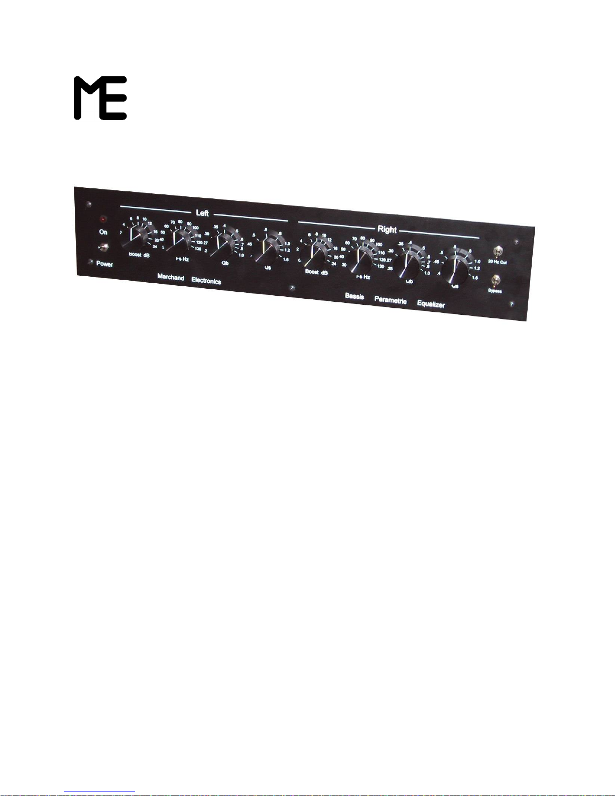
The BASSIS is a specialized electronic
equalizer which enables acoustic-suspension
(closed-box) loudspeakers to take on a wide
range of alternative bass responses improving
some vented (bass-reflex) designs.
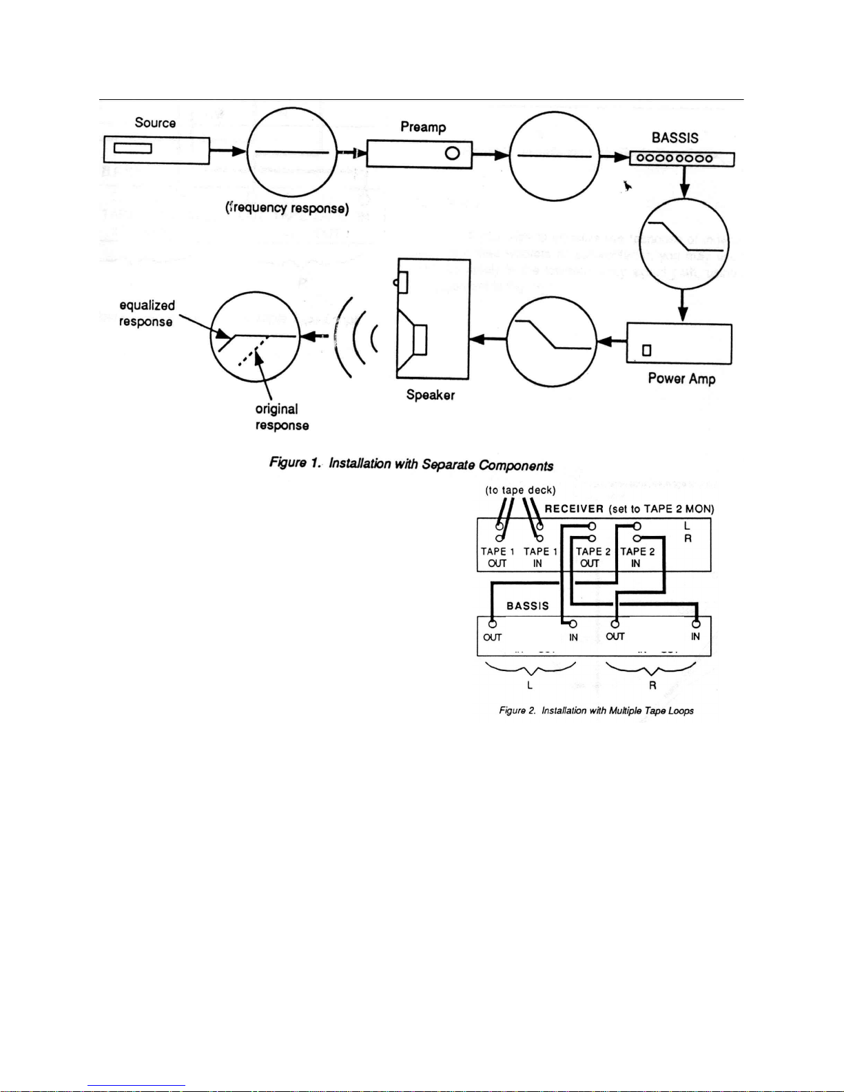
By adjusting the front panel controls, the linelevel audio signal is equalized as the exact
inverse of a given loudspeaker's bass response,
and the new bass cutoff frequency and damping
are defined. The filtered signal is then passed to
the power amp and on to the speakers, where the
existing bass response is cancelled and replaced
by the desired bass response. Figure 1 illustrates
the frequency response at various points in the
signal path.
Marchand Electronics Inc www.marchandelec.com
1
Page 2
INSTALLATION
There are several ways of connecting the
BASSIS to you system, depending upon your
present setup. In any case, make sure all
components are turned off while making
connections, and read the rear panel labelling
carefully. Do not apply power to the unit when
installation is complete. You must make the
adjustments described in "Operation" first.
SEPARATE COMPONENTS
If you own a separate preamp/power amp
combination, you can use the arrangement shown
in Figure 1, where the OUTPUT from the preamp
is connected to the BASSIS' INPUT jacks, and
the BASSIS' OUTPUT jacks are connected to
your power amp's INPUTs. The BYPASS switch
removes the BASSIS circuitry from the signal path
by connecting the INPUT directly to the OUTPUT.
This allows easy evaluation of the equalizer's
effectiveness.
If you own an integrated amplifier or receiver
with PREAMP OUT and POWER AMP IN jacks,
the same connection as for separates can be
used.
MULTIPLE TAPE LOOPS
If your integrated amp or receiver has an
unused tape loop (or a dedicated signalprocessing loop), you may connect the BASSIS
as shown in Figure 2, below.
Be sure to press the TAPE 2 MON button on your
receiver. You can remove the BASSIS from the
signal path in two ways now: (1) turn off the
TAPE 2 MON button on your receiver, or (2) use
the BYPASS switch on the BASSIS.
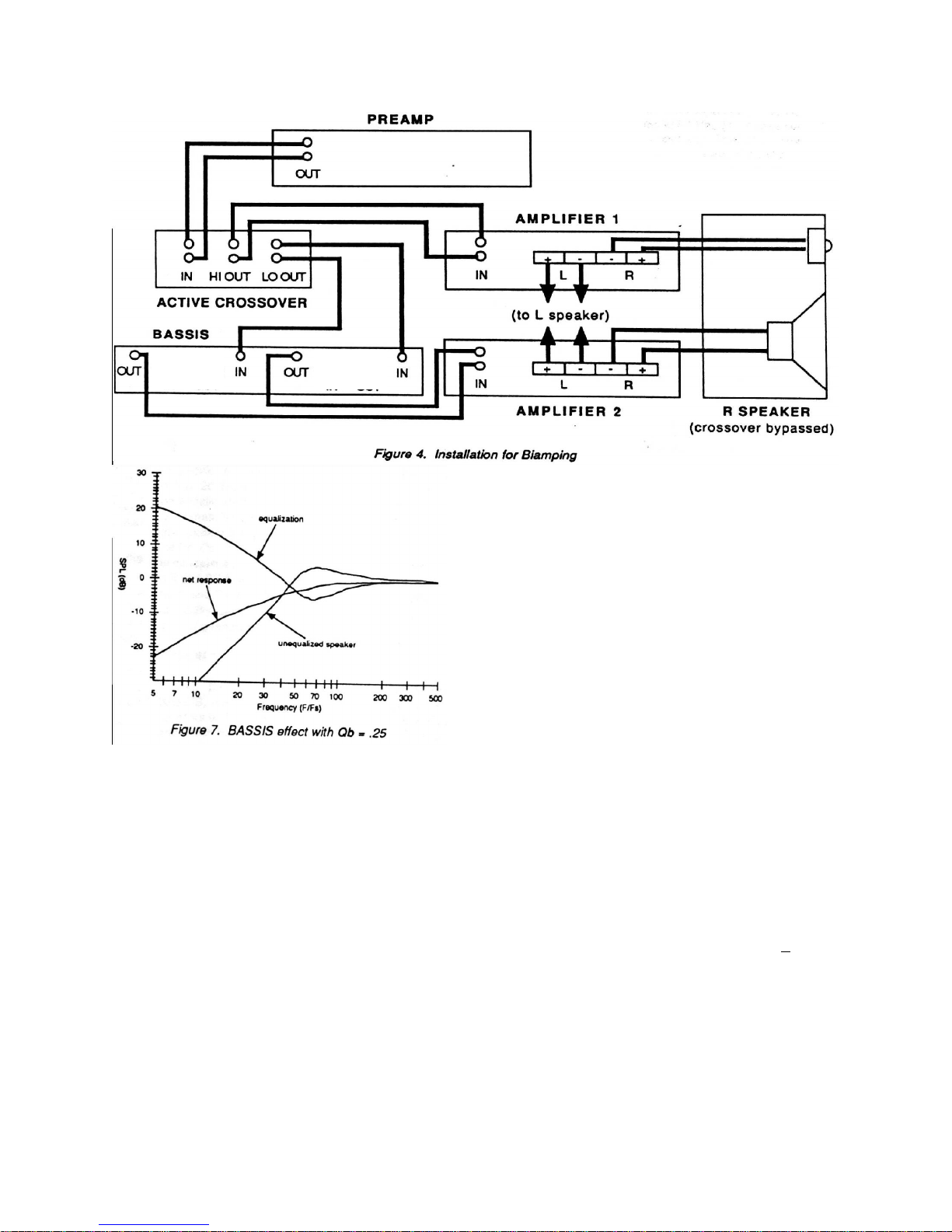
BIAMPING
If you wish to equalize the response of
independently amplified woofers or subwoofer(s),
you may use the BASSIS solely in the lowfrequency signal path, using the arrangement in
Figure 4.
Marchand Electronics Inc www.marchandelec.com
2
Page 3
OPERATION
The various controls on the BASSIS must be
adjusted to match your system's requirements
before power is applied to the unit. If the 24 dB
(factor of 16) maximum BOOST setting is applied
incorrectly, damage to your speakers and/or
amplifier may result.
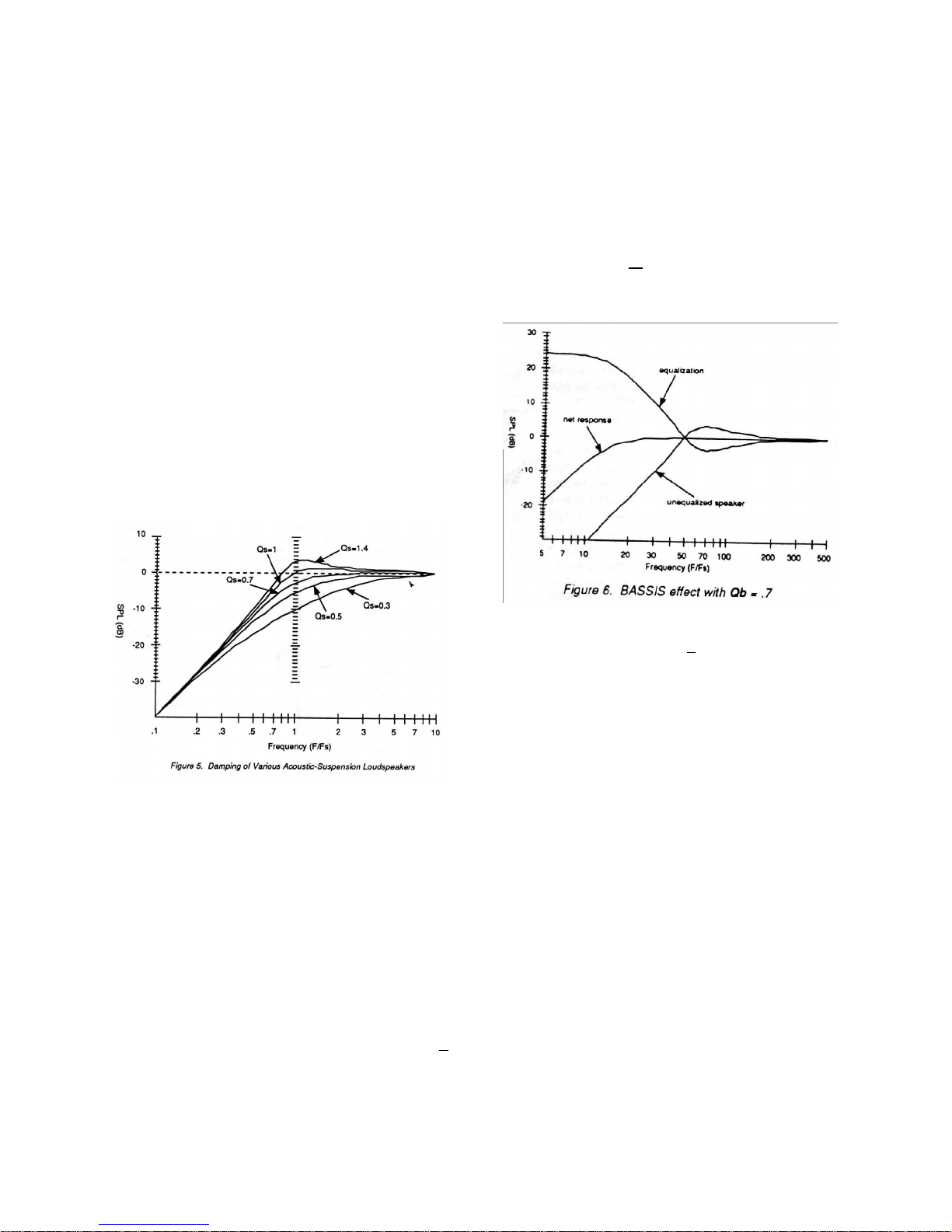
SETTING Qs
Figure 5 shows the bass response of various
acoustic-suspension loudspeakers. If the
speaker's Q is greater than 0.7, the response may
reach a peak at the "resonant frequency", then fall
off at a rate of 12 dB/octave at lower frequencies.
If your speaker has a "boomy" or "heavy" sound,
then it is likely that it Q is in the "underdamped"
range from 1.0 to 1.6. On the other hand,
speakers whose Q is .5 or .6 will be "welldamped", with a "tight" or even "lightweight"
sound (due to the prematurely-falling bass
response).
speaker's value for Qs is .5, then Figure 5 shows
that its -3 dB point is near 1.6 x Fs. Thus, if your
specs indicate a -3dB poi9nt of 75 Hz, then a
setting of Fs = 75/1.6=45Hz should be used. On
the other hand if your speaker has Qs= 1.4
(boomy-sounding), then Figure 5 indicates its -3
dB point is near .65 x Fs. Hence if its
specifications indicate a frequency response like:
"52 Hz to 22 kHz + 3dB", then you should use a
setting of Fs + 52/.65 = 80Hz. Finally, if you
assume Qs = .7 for your speakers, then Fs
equals the specified -3 dB point.
You must adjust the Left and Right channel
controls labelled Qs (Speaker Q) according to
your own speakers' characteristics. (You will
ordinarily use the same settings for Left and Right
channels.) Choose a value which approximates
the damping for your speakers, as suggested
above. If in doubt, use a setting around .7,
corresponding to the value most speaker
designers aim for. You can later fine-tune the
setting if necessary.
Setting Fs
You must now set the Left and Right channel
Fs (Speaker Corner Frequency or -- less
accurately -- Resonant Frequency) controls. If
you have frequency response specifications for
your loudspeakers of the form:"55 Hz to 18 kHz +
3dB" or ".3 dB point at 75 Hz", you can
approximate Fs by making use of Figure 5 and
your estimate for Qs. For example, if your
If you have no frequency response specs for
your loudspeakers, or if the specs are of the form
"50 Hz to 20 kHz" (without + x dB limits) then you
will have to estimate Fs. Most medium-size
"bookshelf" speakers have Fs around 65 Hz;
compact speakers (enclosure less than 14" high)
may have Fs closer to 80 Hz; large speakers
(greater than 30" high) may have Fs around 4050 Hz. For those tiny die-cast speakers like
Radio Shack's Minimus 7, try a value of 100 Hz or
higher for Fs, with Qs around .8 or .9.
While these settings are not too critical, it is
important to get in the ballpark of the correct
setting before using the BASSIS. The settings
may be fine-tuned later if necessary. As an
example of the effect of a severe mismatch,
suppose your speaker has Fs = 50 Hz, and Qs =
1, and suppose that you incorrectly set the
BASSIS according to Fs =100 Hz, Qs = .5. If you
make the remaining adjustments (Boost and Qb,
as described below) to try to extend the bass
response, the BASSIS will give a 6 dB boost
Marchand Electronics Inc www.marchandelec.com
3
Page 4
In the net response at 100 Hz and more than 12
dB too much bass at 50 Hz. (This speaker would
be nearly flat to 50 Hz. without equalization.) The
unnecessary bass boost will give a very "heavy"
sound to most recordings, and may damage the
speakers or cause distortion when listening at
high levels.
SETTING BOOST
Once the correct settings of Fs and Qs have
been made to match your loudspeakers, you may
never need to readjust these controls. However,
the remaining controls -- BOOST and Qb -- may
be adjusted to give the best results with your
choice of listening levels and source material.
BOOST indicates the amount by which low
frequency signals are amplified. If the Fs and Qs
setting are correct, only those frequencies where
your speaker is deficient will be amplified, so that
the effect is to extend bass response. (In
contrast, the BASS control on your receiver or
preamp indiscriminately boosts the entire lowfrequency portion on the signal, often leading to a
"boomy" or "heavy" quality.) A setting of BOOST
= 0 dB will not extend the bass, but will allow you
to effectively adjust your woofer's damping by
changing Qb as described below. A setting of
BOOST = 12 dB will extend bass response one
octave lower, and a setting of BOOST = 24 dB
will extend bass by two octaves.
SETTING Qb
The best setting for Qb is largely dependent
upon your taste and on the listening-room
acoustics. This control adjusts the Q (see Figure
5) of the new bass response dictated by the
BASSIS. If you want a very "tight" sound, choose
a Qb = .5 or smaller. If you want a "looser", more
"full" bass, use Qb = 1. Qb = .7 gives the
"maximally-flat" response. Figures 6 and 7 show
the results when the BASSIS is used to correct a
somewhat boomy-sounding speaker whose
response drops below 60 Hz (Qs = 1.4, Fs = 60).
In both cases BOOST = 24 dB is used, but in
Figure 6 a setting of Qb = .7 is used, while in
Figure 7 Qb = .25 is used.
It is interesting to note that settings of Qb< .5 give
a transient response with absolutely no "ringing",
so that the BASSIS allows you to achieve a "nonresonant" bass response without need for a
refridgerator-sized "transmission-line"
loudspeaker enclosure.
Marchand Electronics Inc www.marchandelec.com
4
Page 5

VENTED SPEAKERS
The BASSIS can be used to reduce the
boominess of poorly tuned vented ("ported",
"bass-reflex", or "passive radiator") speakers. In
this case, use a setting of BOOST = 0 dB (never
boost the bass below the resonant frequency of a
vented speaker!), Qs = 1.4, and adjust Qb to your
taste. Or, you can plug the vent and forego the
efficiency advantage of the vented design,
allowing you to use the entire range of
equalization options as you would for an acousticsuspension loudspeaker.
extend smoothly into the lower bass, particularly
when using high-quality source material.
On the other hand, extending the bass
response will make your system more sensitive to
"standing waves" in the listening room. You may
have to experiment with new locations for your
loudspeakers or listening seat to obtain the
smoothese overall bass response.
TECHNICAL DESCRIPTION
The equalization offered by the BASSIS can be
described in terms of the biquadratic transfer
function:
FINAL ADJUSTMENTS
You are now ready to apply power to your
system including the BASSIS. Advance your
VOLUME control slowly to make sure the unit is
working properly. If you have difficulties, see the
"Troubleshooting" section of this manual
(Appendix F). There are a few additional points to
keep in mind to obtain optimum performance.
If your source materialis LP records, you should
test your system's sensitivity to record warps.
Remove the grilles from your speakers. With the
VOLUME control set low and the BASSIS set with
BOOST = 24 dB, play the silent lead-in observing
your woofer cones. If a significant "pumping"
motion is visible at your normal VOLUME setting,
engage the 20 HZ CUT filter on the BASSIS.
Even when properly adjusted, the bass
extension offered by the BASSIS must be used
with discretion. While the BASSIS can give a 61/2" woofer the same bass response as that of a
12" woofer, it cannot increase the power handling
of small speakers. Do not engage your preamp
or receiver's LOUDNESS button or make
excellive use of the BASS tone control while
using the BASSIS. When listening at high
VOLUME levels to material with significant lowbass content, it is wise to reduce the BOOST
setting, reduce Qb, or BYPASS the unit entirely.
Fortunately, the low-bass content of most
recordings is much smaller than the content of
the remaining frequency range. In these cases
the low-frequecy boost applied by the BASSIS will
not impair the speaker or amplifier power
capabilities.
When using the BASSIS, don't expect to hear
the sort of elevated bass produced by turning up
your preamp or receiver's BASS tone control or
pressing the LOUDNESS button. Instead, the
mid-bass will be reproduced with impoved
neutrality and "openness", and the response will
2
w
+ 2 dswss + s
s
2
G(s)= --------------------------------------
2
w
+ 2 dbwbs + s
b
where ws and ds are the corner frequency
and damping ratio of the woofer and wb and d
are the new corner frequency and damping ration
chosen by the user (w =2piF and d =0.5/Q). The
numerator cancels the 2nd-order high-pass effect
of the acoustic-suspension woofer and the
denominator defines the new 2nd-order cutoff.
CIRCUIT
The circuitry for each channel of the BASSIS is
contained on an individual printed circuit board
(PC board), using high-speed op-amps and closetolerance passive components. A power supply is
contained on a third board. The schematic
diagram of a single channel is shown in Appendix
A.
The heart of the circuit is a 4-amplifier
biquadratic filter, supplemented with additional opamps to allow the independent adjustment of the
damping and cutoff frequency pararmeters. Opamps IC1, IC2 and IC3 provide the equalization,
while IIC4A is part of the 20 Hz CUT filer. Opamp IC4B provide low output impedance and high
current capability, to allow long cable runs with
minimal loading effects.
Dual potentiometer VR3 adjusts the frequency
matching the speaker's corner frequency over the
range: Fs = 30 Hz to 130 Hz. Potentioometer
VR2 adjusts the damping which exactly cancels
the speaker's response, for speakers with Qs
from .4 to 1.6. Potentiometers VR1 and VR4 set
the corner frequency and damping of the new
bass response over the range: Fb = Fs to Fs/4
and Qb = .25 to 1. Since each octave of bass
extension requires 12 dB of amplification at low
2
b
Marchand Electronics Inc www.marchandelec.com
5
Page 6

frequencies, pot VR1 is actually labelled BOOST,
with a range of 0 to 24 dB.
Switch S1 activates the 20 HZ CUT (high-pass,
infrasonic, or "subsonic") filter with an 18
dB/octave slope below 20 Hz, to avoid the
amplification of inaudible but potentially
destructive low-frequency signals. Switch S2
combines the Left and Right channels at
frequencies below the speaker's original corner
frequency (provided the settings for Fs, Qs,
BOOST, and Qb are identical for both channels)
to cancel out-of-phase RUMBLE signals. Switch
S4 provides a BYPASS function to eliminate the
equalizer from the signal pather, and Swith S3
allows the user to regain tape monitoring
capability, in the event that the BASSIS is used in
the sole tape loop of a receiver or preamp.
operation. Simply follow the steps in the
"Assembly" section of this manual, but wire the
inputs of a second + 15 V power supply to the
power cord as well, and power the Right-channel
PC board from this power supply.
OPTION 3
On the other hand, if the BASSIS is to be
used with a single-channel, independentlyamplified subwoofer, then only a single PC board
need be assembled, and a smaller enclosure may
be employed. Assembly is the same as
described in this manual, except that the switches
may be SPDT rather than DPDT.
ASSEMBLY (KIT VERSION)
OPTION 1
If you are constructing your own enclosure for
the BASSIS, you may choose to calculate the
values of fixed resistors which reflect your
particular speaker's Fs and Qs, and which provide
a fixed amount of boost. This allows you to
eliminate all but a
Single potentiometer -- which controls the
damping (Qb). Since the setting of the Qb control
influences the level of bass about the new corner
frequency (compare Figures 6 and 7), you retain
control of the net bass extension. To implement
this option, follow the assembly procedure
detailed in the next section of this manual, except:
(a) leave out the Molex connectors which attach
the BOOST and Fs pots to the PC board; (b) wire
only that part of Molex connector P2 which
attaches the Qb pot to the PC board; (c)
recalculate the values of resistors R7, R8, R16,
R4, and R26 according to your speakers'
characteristics and the desired amount of boost:
R7 = R8 = 1/(6.28 x Fs x C1)
R
R4 = R26 = R28 x 10
= R19 x Q
16
s
boost/40
.
Where BOOST is given in dB. Now you can use
a dual 10k linear pot to adjust the damping (Qb)
of the Left and Right channels simultaneously.
Or, if you want to eliminate the remaining control
as well, remove VR4 and recalculate R11 for the
desired (fixed) value of Qb:
R11 = R2 x Qb.
OPTION 2
There is space in the standard BASSIS
enclosure for an additional power supply for
constructors interested in true dual-mono
The parts for a stereo implementation include:
two BASSIS printed circuit boards and
components, one + 15 V power supply assembly
(such as Marchand Electronics' Model PS10), and
one enclosure with hardware. The Appendices of
this manual contain a detailed Overall Parts List
as well as a PC Board Parts List. You will first
assemble the circuit boards, then mount them in
the enclosure and attach the front panel controls.
GENERAL WIRING PRACTICE
The tools necessary to assemble the BASSIS
include: a 15 - 30W soldering pencil, rosin-core
solder, wire cutters, and a Phillips-head
screwdriver. Other useful tools are: a
desoldering tool or solder wick (to remove excess
solder), a project holder, long-nose pliers, and a
wire stripper. A clean, well-lit working area will
minimize frustrations.
When soldering a component to the circuit
board, first mount the component so that it fits
snugly against the silkscreened side of the board.
Next, heat the component lead and the circuit
board trace (on the foil side) simultaneously with
the soldering pencil and apply solder until it melts
and flows around the component lead. With
practice the entire process should take only 5
seconds or so. Remove the pencil and allow the
connection to cool for a few seconds before
moving. Cut off the excess lead close to the
solder joint. If a solder bridge was inadvertently
made to another trace, remove the solder
carefully with a desoldering bulb or braid. Keep
the tip of the soldering pencil clean by wiping on a
damp sponge every few minutes.
Components can be identified as follows.
Resistors use the 4-band color code in the chart
shown below. The fifth band is always brown,
indicating 1% tolerance. For example, a resistor
Marchand Electronics Inc www.marchandelec.com
6
Page 7

marked Brown-Black-Black-Gold-Brown is a 10
Ω resistor with 1% tolerance.
1st, 2nd, & 3rd Bands 4th Band
Black 0 Black x 1
Brown 1 Brown x 10
Red 2 Red x 100
Orange 3 Orange x 1000
Yellow 4 Yellow x 10,000
Green 5 Green x 100,100
Blue 6 Blue x 1,000,000
Violet 7 Silver / 100
Gray 8 Gold / 10
White 9
Figure 8. Resistor Color Code
Capacitors and diodes are individually
marked, though somewhat cryptically. C1 and C4
may be labelled "393", while C5, C7, and C15 are
marked "104K".
Before beginning assembly, it is suggested
that you compare the components to the Parts
List and sort them accordingly. (Look inside the
heat-shrink tubing if anything is missing!)
PC BOARD ASSEMBLY
Assembly of the BASSIS is simplified by a
guide which has been silkscreened on to the
printed circuit boards. Appendix B repeats this
layout diagram. To mount components onto the
boards, observe the placement shown on the
layout diagram and on the silkscreen pattern, and
match with the values shown on the PC Board
Parts List in Appendix D. The following checklist
should be completed, for both the Left and Right
channels.
[ ] [ ] 1. Bend the leads of resistors R1-R35
and solder them in place as shown on the layout
diagram. Cut off the excess leads as you go.
[ ] [ ] 2. Deleted.
[ ] [ ] 3. Mount diodes D1-D4 and solder them
in place. Be sure to observe the correct polarity
by positioning the side with the band as shown in
the diagram.
[ ] [ ] 4. Mount and solder the four (4) IC
sockets in place on the circuit board. Be sure the
side with the notch is oriented as shown. Do not
insert the op-amps into these sockets yet.
[ ] [ ] 5. Install the aluminum electrolytic
capacitors C8 and C14, being careful to orient the
+ and - leads as shown. Install the nonpolar
electrolytic capacitor C9 with either orientation.
[ ] [ ] 6. Install the remaining polypropylene,
polyester and ceramic capacitors C1-C7, C10-C13, and C15-C16. (These can be oriented either
way.)
[ ] [ ] 7. Install Q1, 2N5087.
[ ] [ ] 8. Install Q2, 2N2222.
[ ] [ ] 9. Mount the 3-pin male Molex connector
and the five (5) 5-pin male Molex connectors
according to the diagram. The edge with the
plastic protrusion corresponds to the band on the
layout diagram.
[ ] [ ] 10. Press op-amps 1C1-1C4 into the four
IC sockets, being sure to orient them so that the
notch matches the notch on the sockets, as
shown on the diagram. You may need to (gently)
bend the leads inward slightly to match the holes
in the sockets. If you resolder any of the socket
leads later, remove the corresponding op-amp
first to protect it from excessive heating.
Now inspect the foil side of the board for solder
splashes or bridges and remove them with the
desoldering tool. Check for any empty holes,
possibly indicating a missing component. (Some
unused holes may remain, to allow substitution of
capacitors with differing physical dimensions.)
Double-check the orientation of the aluminum
electrolytic capacitors, diodes, transistors,
connectors, and ICs.
L R
Marchand Electronics Inc www.marchandelec.com
CHASSIS WIRING
At this point you should have assembled the
Left and Right channel PC boards, and a + 15 V
power supply. The Overall Parts List in Appendix
E details the parts needed for assembling the
BASSIS chassis. Appendix C sketches the
interior of the unit after completion of a single
channel.
Do not apply power to the unit until all the
assembly is complete and you've read the
"Operation" section of this manual.
7
Page 8

[ ] 11. Mount the BASSIS PC boards and power
Front Panel
DPST rocker switch
Rear Panel
Fuse Holder
Rear Panel
Power entry
Rear Panel
Voltage selector
GREEN/
YELLOW
N
L
PS10 transformer
terminal block
WHITE
BLACK
WHITE
BLACK
BLACK
BLACK
BROWN
RED
RED
Wire to
case
WHITE
Sold er l ug
Re sistor
Wire to PS1 0 outp u t
gr ound
supply inside your enclosure with standoffs and
#6 screws. The PS 10-power supply should be
oriented with the transformer closer to the rear
panel.
[ ] 12. Mount potentiometers VR1-VR4 for each
channel (total of eight (8) pots on the inside of the
front panel. The dual pots (VR1 and VR3)
correspond to the BOOST and Fs labels on the
front panel. The pots should have their solder
lugs facing up.
[ ] 13. Mount the fuseholder on the rear panel but
do not insert the fuse yet.
[ ] 14. Mount the power entry connector onto the
rear panel.
[ ] 15. Mount the DPDT voltage selector switch
on the rear panel.
[ ] 16. Mount the RCA bukhead connectors on
the rear panel. Two have black insulators and
two have red insulators. Mount the red
connectors in the right channel and the black
ones in the left channel.
Power entry with voltage selector switch on rear
panel and rocker switch on front panel.
Power entry with voltage selector switch.
The PS10 power supply of the crossover should
be grounded to the cabinet through a power
resistor.
Solder one lead of the 2400 Ohm power resistor
to the solder lug.
Solder a 3” length of wire to the other end of the
power resistor.
Install the shrink tubing over the resistor and part
of the solder lug.
Attach the solder lug to the cabinet using one of
the 6-32 screws on the front panel.
Insert the free end of the wire in the center
terminal of the three position terminal block of the
PS10 output. This is the neutral DC output.
Marchand Electronics Inc www.marchandelec.com
Now the AC power wiring will be hooked up to
the power supply.
8
Page 9

Use high voltage (thick insulation) #22 hookup
teflon shoulder washer
RCA connector
teflon flat washer
gold plated solder lug
gold plated nut
rear panel
RCA connector mounting cross section
wire to make the connections between the power
entry connector, the power switch on the front
panel and the power selector switch on the rear
panel and the fuse holder. Install heat shrink
tubing over all junctions. Use wire colors as
shown.
Make sure to securely install the grounding wire
between the ground terminal on the power entry
connector and the chassis. Solder a 3” piece of
green/yellow hookup wire to one of the solder lugs
provided. Solder the free end of the wire to the
ground terminal and secure the solder lug to the
chassis with one of the 6/32 screws holding the
rear panel.
Set the voltage selector switch to the proper
voltage before proceeding.
Install a 1A fuse in the fuse holder.
We will now test the power supply. Plug the
cord in and turn on the power switch. The two
LED indicators on the power supply and the front
panel LED indicator should light up.
UNPLUG the power cord before proceeding.
[ ] 17. Cut a 4" piece of brown wire and 4" of red
wire, strip 1/4" from each end, and attach a spade
lug to one end of each wire. Slide a 1-1/2" piece
of heat-shrink tubing onto the other end of each
wire. Solder the brown wire to the cathode lead of
the front panel LED (the cathode is the lead closer
to the flattened edge of the LED). Solder the red
wire to a 10k resistor. Solder the other end of this
resistor to the remaining LED lead. Slide the
heat-shrink over the exposed leads and heat with
a match. Mount the LED in the appropriate
socket on the front panel. Leave the other ends
of these wires loose for now.
For the remaining steps, the codes shown in
Figure 9 will be used to refer to the lugs on the
potentiometers, switches and Molex connectors.
[ ] [ ] 18. For the Left and Right channel
circuit boards, cut pieces of red, brown, and
orange wire long enough to reach from male
Molex connector P4 on the circuit board to the
output terminals on the power supply (with a few
inches to spare). Strip 1/4" from each end.
Attach spade lugs to one end of each of the three
wires and twist the wires together for neatness (-unless you're color-blind, in which case you
should attach the wires one at a time to keep
track!). Attach Molex terminal pins to the other
end of each wire. Using the coding in Figure 9,
press the pin attached to the brown wire into jack
A in a 30pin female Molex connector, and press
the pins on the red and orange wires into jacks B
and C, respectively. Snap the female connector
onto P4.
[ ] [ ] 19. Screw the spade lugs attached to the
brown wires for each channel to the -15 V
terminal of the power supply, along with the spade
lug attached to the cathode of the front panel
LED. Screw the spade lugs attached to the red
wires to the Ground terminal on the power supply.
Screw the spade lugs attached to the orange
wires to the + 15 V terminal of the power supply,
along with the spade lug attached to the anode of
the front panel LED. These connections are
critical. Double check that you've linked jack A of
Marchand Electronics Inc www.marchandelec.com
9
Page 10

the Molex connector to the - 15 V terminal, jack B
to Ground, and jack C to + 15 V.
[ ] [ ] 20. Using a short piece of bared wire link
lugs C and F together on the BOOST pots, and
link lugs A and D together on the Fs pots.
[ ] [ ] 21. Cut 5 wires of different colors, long
enough to reach from male Molex connector P1
on the circuit board to the corresponding BOOST
pot. Strip 1/4" from each end and twist the wires
together for neatness. Attach Molex terminal pins
to one end of each wire, and slide a 3/4" piece of
heat-shrink tubing onto the other end. Press the
terminal pins into a 5-pin female Molex connector
as shown in Figure 9. Solder the other end of
each wire to the lugs of the BOOST pot,
observing the colors so that (see Figure 9): jack
A on the Molex connector connects to solder lug
D on the pot, jack B connects to lug E, jack C
connects to lug F, jack D connects to lug B, and
jack E connects to lug A. Slide the heat-shrink
over the solder joint and heat with a match. Snap
the female Molex connector onto male connector
P1.
[ ] [ ] 22. Using the same procedure as in Step
21 (don't forget the heatshrink tubing), connect
jack A of the female Molex connector you will use
with P3, to lug F on the Fs pot. Connect jack B to
lug E, jack C to lug D, jack D to lug B and jack E
to lug C. Snap the Molex connector onto P3 on
the circuit board.
[ ] [ ] 23. Using the same procedure as in Step
21, connect jack A of the female Molex connector
corresponding with P2, to lug A on the Qb pot.
Connect jack B to lug B on the same pot.
Connect jack C to lug C on the same pot, and use
a short piece of wire to attach lug C of the Qb pot
to lug C of the Qs pot. Now connect jack D to lug
B of the Qs pot and jack E to lug A of the Qs pot.
Snap the Molex connector onto P2 on the circuit
board.
[ ] [ ] 24. Using the same procedure, connect
jack A of the female Molex connector
corresponding to P5, to lug D (Left channel) or lug
A (Right channel) of a DPDT switch (see Figure
9). Be sure you are holding the switch so that the
keyhole tab is on the underside of the shaft.
Connect jack B to lug E (Left channel) or lug B
(Right channel). Connect jack C to lug F (Left
channel) or lug C (Right channel) of the same
switch. Skip jack D on the Molex connector. Snap
the Molex connector onto P5 on the circuit board.
When both channels are completed, mount the
DPDT switch in the 20 HZ CUT hole.
[ ] [ ] 25. Connect jack A of the Molex
connector P6 to lug F (Left channel) or lug C
(Right channel) of the remaining DPDT switch.
Connect jack D of the Molex connector to lug E (L
channel) or lug B (R channel) of the switch.
Connect jack E to lug D (L channel) or lug A (R
channel) of the switch. Mount this switch in the
BYPASS hole on the front panel.
[ ] [ ] 26. Install a jumper wire between jack B
of connector P6 and jack C of same. Snap the
Molex connector onto P6 on the circuit board.
[ ] [ ] 27. Install a jumper wire between the
tape-in and tape-out terminals of the 8-position
blue terminal block on the WM8 circuit boards.
[ ] [ ] 28. Mount all the knobs onto the pots,
and insert the fuse into the fuseholder.
Note that the knobs are mounted so that they will
turn the same angle fully clockwise as fully
counterclockwise.
You have now completed the assembly of your
BASSIS. Double check that you've completed all
the steps. At this point you may plug the unit into
a wall outlet and turn on the POWER switch to
observe whether the power light comes on.
However, do NOT attach it to your system until
you've made the adjustments discussed in
"Operation".
Marchand Electronics Inc www.marchandelec.com
10
Page 11

APPENDIX A Schematic Diagram
WM8 BASSIS
(c) 2001 Marchand Electronics Inc.
C4
IC2B
gnd
Tape In
R2
R1
R5
R9
R35
R8
R21
VR3A
FS
C1
IC1B
R6R7VR3B
IC3A
R10
R11R3R4
R27
R26
R25
C7
C15
R18
C5
C16
R24
R34
Tape Out
Input
R29
R28
GND
IC3B
R12
R13
R19
IC4B
R15
R16
VR2
Qs
R32
R17
R14
R22
Out
C3C2C1
C8
+15Volt
-15Volt
R22*
R23
R30
C10
D2*D2D1
S3
Tape
Mon
VR1A
BOOST
VR1B
VR4
Qb
C9C6 IC4A
IC1A
IC2A
S4 Bypass
S1 20Hz cut
C13
D3
Q1
Q2
RLY1
Muting
S2 Rumble
C2P65
3
211P6432
P5P55
Off-board connection
Marchand Electronics Inc www.marchandelec.com
11
Page 12

APPENDIX B PC board Layout
Marchand Electronics Inc www.marchandelec.com
12
Page 13

Marchand Electronics Inc www.marchandelec.com
13
Page 14

Marchand Electronics Inc www.marchandelec.com
Typical cabinet front panel layout
14
Page 15

Parts list for WM8-K board
----------------------------------------------------------------------- Bag #1
-----------------------------------------------------------------------R32 1 10.0 Ohm 1% Metal Film
R23, R30 2 24.9K 1% Metal Film
R10 1 33.2K 1% Metal Film
R25 1 40.2K 1% Metal Film
R14, R17 ,R6, R9 4 49.9K 1% Metal Film
R15 1 52.3K 1% Metal Film
R1,2,5,11,12,13,19,22,28,29,35 11 100 K 1% Metal Film
R3, R27 2 133 K 1% Metal Film
R7, R8, R16 , R21 4 162 K 1% Metal Film
R4, R18, R26 3 402 K 1% Metal Film
R24, R34 2 1.00M 1% Metal Film
R22* 1 10M 5% Carbon Film
C1, C4 2 0.033uF, 2% Polypropylene
C2, C3, C11, C13 4 0.1 uF, Ceramic Axial
C10 1 0.22 uF, Stacked Film
C5, C7, C15 3 0.1 uF, Polypropylene
C8, C14 2 330 uF, 25V Aluminum
C9 1 10 uF, 25V Aluminum, Non-Polar
C6, C16 2 1.0 uF, Stacked Film
D1, D2 2 1N4937 1A fast
D2* 1 1N4148 small signal
D3 1 1N5232B (5.6V zener diode)
Q1 1 2N5087
Q2 1 2N2222
IC1, IC2, IC3, IC4 4 OPA2134PA
4 IC socket, 8pin
1 Molex connector, 3pin, male
5 Molex connector, 5pin, male
1 Molex connector, 3pin, female + pins
5 Molex connector, 5pin, female + pins
1 DPDT relay, 24V coil
1 8 pos terminal block
1 Circuit board WM8, 3.2" * 4.15"
NOTE: D2* and R22* are marked D2 and R22.
D2* and R22* are are located near diode D3.
----------------------------------------------------------------------- Bag #2
----------------------------------------------------------------------- For dual single
VR1, VR3 4 2 10 K Dual Pot., Linear
VR2, VR4 4 2 10 K Pot., Linear
1 1 DPDT rocker switch
2’ 1’ 1/8" shrink tubing
6’ 3’ Hookup wire, stranded, 22AWG, Brown
6’ 3’ Hookup wire, stranded, 22AWG, Red
6’ 3’ Hookup wire, stranded, 22AWG, Orange
6’ 3’ Hookup wire, stranded, 22AWG, Yellow
6’ 3’ Hookup wire, stranded, 22AWG, Green
Marchand Electronics Inc www.marchandelec.com
15
Page 16

Parts list for WM8- KK, full kit
------------------------------------------------------------------------
Bag #3
------------------------------------------------------------------------
2 Bag-1, WM8-KK board kit
1 Bag-2, Dual model
1 PS10-K Power supply kit
1 Fuseholder, D type
1 Fuse, 1A
1 DPST Rocker Power switch
1 Voltage Selector Switch
1 Power Entry Connector
2 #6 solder lug
1 2.4K, 1W resistor
2 Gold plated RCA jacks, red
2 Gold plated RCA jacks, black
1 Line cord, 3-wire IEC
8 Knob
4 4/40 x 3/8" philips head machine screw
4 4/40 locknut
12 Standoff, 1/2", #6
12 6-32 x 1/4" philips head machine screw
16 6-32 x 1/4" philips head machine screw,black
5 6-32 x 1/2" philips head machine screw
5 6-32 x 5/8" button head cap screw
2' Hookup wire, stranded, 22AWG, Brown
2' Hookup wire, stranded, 22AWG, Red
2' Hookup wire, stranded, 22AWG, Orange
1' HV wire Yellow/Green
2' HV wire white
2' HV wire blck
1' HV wire red
1' HV wire brown
6" 1/4" heatshrink tubing
1 Hex wrench 1/16”
1 Hex wrench 5/64”
1 Cabinet base
1 Cabinet front
1 Cabinet front adapter plate
1 Cabinet rear
1 Cabinet top
4 Rubber bumper + screw
Marchand Electronics Inc www.marchandelec.com
16
 Loading...