

Page 1

VDV-B90
ADV-B40
OPERATING INSTRUCTIONS
Page 2
VDV-B90 | ENGLISH
A
Abb. A
DIAGRAM A
ILLUSTRATION A
AFBEELDING A
TECHNIKBOX • POWER BOX • POWERBOX • POWERBOX
GB
11
1.1
1
2
3
20
10
9
4
5
8
6
2
7
12
11
88
Page 3
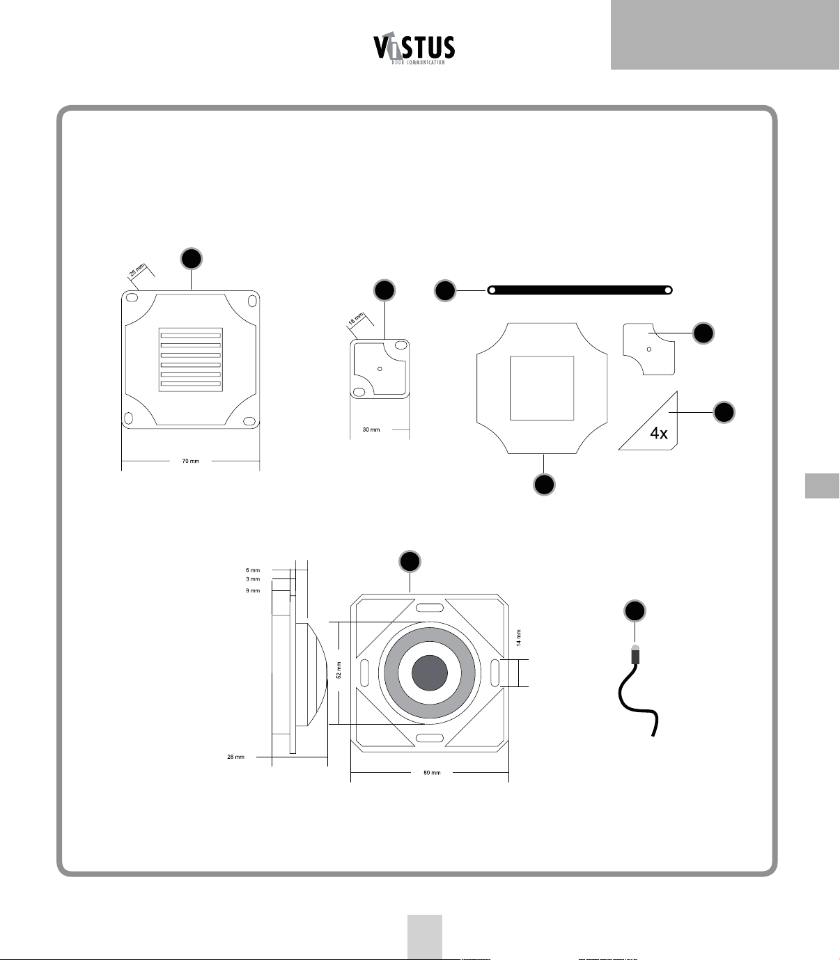
Abb. B
B
DIAGRAM B
ILLUSTRATION B
AFBEELDING B
18
19
ENGLISH | ADV-B40
2x
13
14
15
17
16
GB
21
9
Page 4

VDV-B90 | ENGLISH
GB
INTRODUCTION
VIDEO INTERCOM MODULE VDV-B90
AUDIO INTERCOM MODULE ADV-B40
Thank you for purchasing an m-e product. This add-on module allows
you to equip existing intercoms, which are fitted inside e.g. letter box
systems or pillars, with the VISTADOOR system or convert them to this.
Internal units of the VISTADOOR and VISTUS systems can be connected.
It is suitable for connecting up to six parties.
CONTENTS
Tech box
Loudspeaker module c/w 50 cm long connector cable
Microphone module c/w 50 cm long connector cable
Camera module c/w 50 cm long connector cable (only VDV B90)
Adhesive pads for securing in position
Light sensor c/w 50 cm long connector cable
Available as optional accessories
External camera mod. VDV 500 Xcam, Xcam Pro1, Xcam Pro2, Xcam Pro3
Cap rail power supply unit mod. DT 2000
Mains adapter mod. ST 1000
Requirements
A simple make contact for each apartment is all that is needed in terms
of bell push. If a loudspeaker and microphone are present, these must
meet the following specifications if they are to work properly with the
add-on module:
Loudspeaker
Impedance: 8 ohms
Power: minimum of 0.5 watts
Microphone
Electret microphone
Phantom power: 5 volts (ensure correct polarity)
If the technical data are not known, to prevent any problems with
voice transmission, you should replace the existing loudspeaker and
microphone with the loudspeaker and microphone supplied.
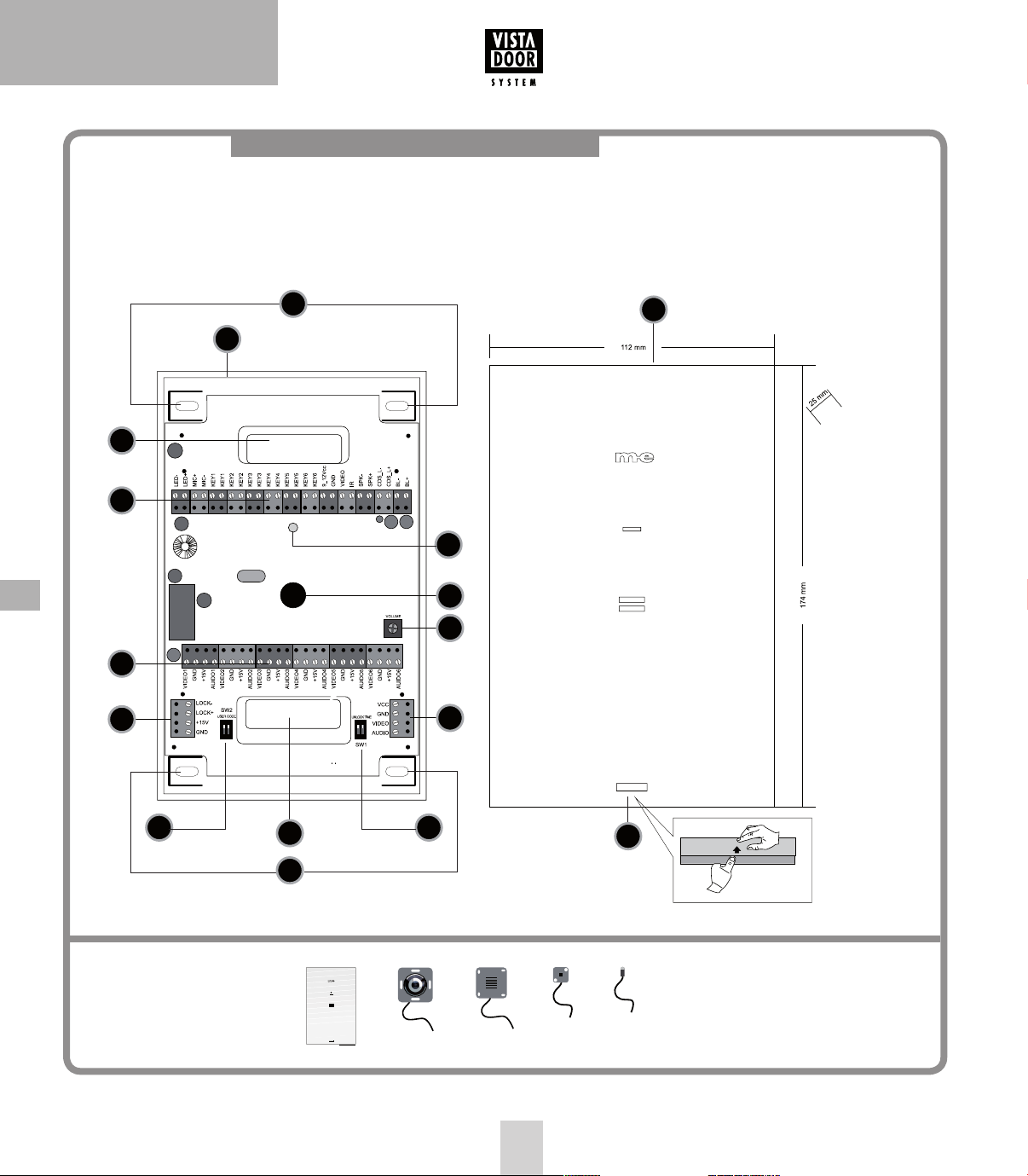
KEY
1. Tech box
1.1. Housing cover
2. Cable entry
3. Terminal (button, microphone, loudspeaker etc.)
4. Terminal (connection for internal units)
5. Terminal for door opener
6. DIP switch user code
7. DIP switch door opener time
8. Terminal for external camera
9. Volume potentiometer
10. Piezoelectric beeper
11. Mounting holes
12. For unlocking housing cover
13. Strain relief (2x)
14. Adhesive pad for microphone module
15. Adhesive pad for camera module (4x)
16. Adhesive pad for loudspeaker module
17. Camera module (only VDV B90)
18. Loudspeaker module
19. Microphone module
20. Power LED
21. CDS sensor
CONNECTION OPTIONS FOR THE TECH BOX
Top connection terminal (26-pole)
LED+ and LED-: This is for connecting an LED which lights up when
the door opener is operated to indicate to the visitor that the door is
being opened. Output: 5 V DC max. 50 mA
MIC+ and MIC-: This is for connecting the microphone, the white
cable to + and the black cable to -.
KEY1 to KEY6 (2 screw terminals each): This is for connecting the
relevant bell push. KEY1 activates the internal unit, which is connected
to VIDEO1 and AUDIO1, etc.
9_12Vcc, GND, VIDEO and IR: This is for connecting the camera
module. Red cable to 9_12Vcc, black cable to GND and yellow cable to
VIDEO. The fourth cable of the camera module is connected to IR.
1010
SPK- and SPK+: This is for connecting the loudspeaker, the red cable
to + and the black cable to -.
CDS_L- and CDS_L+: This is for connecting the brightness sensor,
the red cable to + and the black cable to -.
Page 5

ENGLISH | ADV-B40
BL- and BL+: This is for connecting the name tag lighting. Only LEDs
can be connected; make sure that the polarity is correct.
For the connected LEDs to light up, the brightness sensor must be
connected and shaded over.
Output: 12 V DC max. 60 mA
Bottom connection terminal (24-pole)
This terminal is for connecting the individual apartments. Up to four
internal units can be connected in parallel for each apartment. VIDEO1,
GND, +15V and AUDIO1 for apartment 1, etc.
Left connection terminal (4-pole)
LOCK- and LOCK+: This is for connecting the door opener. Some door
openers have a flyback diode fitted. If this is the case, make sure that
the polarity is correct. If the door opener only responds for a short
time (less than one second), its current consumption is too high. The
door opener should then be replaced with a model which uses less
current (maximum of 0.9 A). Alternatively a relay can be connected up
between the door opener and the terminal.
+15V and GND: This is for connecting the operating voltage.
You do not need to do this if you are using the recommended
star wiring.
Right connection terminal (4-pole)
This is for connecting an additional camera. Do not use the X module
with the VDV-500 Xcam, if the latter is used. The best thing is to cut the
cable to the camera just behind the X module. Then strip the insulation
from the cable. The three wires thus exposed are hooked up to the
connection: red to VCC, black to GND and yellow to Video. If you want
to use a camera from a different manufacturer, this must comply with
the following technical data:
FITTING RECOMMENDATIONS
During fitting, the power supply should be switched off
to avoid short circuits.
The tech box must be attached in such a manner that rain water cannot
penetrate it.
The connection cables of the camera, loudspeaker and microphone
modules, as well as the brightness sensor, should not be extended. They
may however be shortened.
A 3 mm diameter hole is needed for the brightness sensor. The sensor
should be able to be retained in the hole of its own accord; if necessary
you can use hot glue or with an adhesive pad to fix it in position.
Adhesive pads designed especially for the camera, loudspeaker and
microphone modules, respectively, are included. You can use these to
secure those items at their desired locations. If you want to attach the
modules with screws, you should use the relevant module as template.
The loudspeaker and microphone modules should not be fitted directly
next to one another. This is to prevent feedback.
A hole with a diameter of 52 mm is needed for the camera module.
The camera has special markings to help ensure it is fitted correctly.
Given that the height at which the camera module is fitted depends
on local factors, we cannot recommend an optimum mounting height.
A mounting height of 1.5 m to 1.6 m has been a good rule of thumb
in the past.
For the automatic system to work properly, the light sensor should be
fitted at a location where daylight can reach it. If you want to fit the
light sensor to your existing front plate, a 3 mm hole will be needed.
GB
12 V operating voltage, max. 500 mA current consumption, FBAS video
signal (1 Vpp, 75 ohm)
VCC is connected to the positive pole of the camera’s power connection.
GND is connected to the negative pole of the camera’s power
connection.
VIDEO is connected to the video output of the camera. On most
cameras, the negative pole is connected directly to the video ground. In
a few rare cases, the video ground also has to be connected to GND.
Please note that the camera is only supplied with power at this connection when the external camera is activated at the internal unit.
See the drawings for the exact dimensions of the individual modules.
POSSIBLE SETTINGS
The outdoor station offers the following possibilities to set the system
to your personal circumstances:
Volume of the outdoor station
The potentiometer (9) is used to set the volume on the outdoor station.
To set the highest volume, turn the potentiometer carefully clockwise
as far as possible. Reduce the volume by turning in an anti-clockwise
direction.
11
Page 6

VDV-B90 | ENGLISH
GB
ID code
If several outdoor stations are switched in parallel (e.g. at the gate entrance and the house) then the ID code is set via the dip switch (6). This
makes it possible to activate the individual outdoor units in sequence,
e.g. in order to monitor the coverage of the relevant outdoor unit. The
switch is carried out on the indoor station with the ‘monitor’ switch.
ID1 = Switch 1 ‘on’ Switch 2 ‘on’
ID2 = Switch 1 ‘off’ Switch 2 ‘on’
ID3 = Switch 1 ‘on’ Switch 2 ‘off’
Opening time of the door opener
The dip switches (7) are used to set how long the door opener should
be activated. The possible settings are either 1 second or 5 seconds.
5 seconds are set at the factory and function for most standard door
openers.
Switch 1 ‘off’, Switch 2 ‘on’ is equivalent to an
opening time of 1 second.
Switch 1 ‘on’, Switch 2 ‘off’ is equivalent to an
opening time of 5 seconds.
OPERATION
1. Press the bell push-button.
2. The preset ring tone sounds on its inside station/s and the screen
displays the outside station view (VDV-B90 only).
3. Accept the dialogue on the inside unit by briefly pressing the pressto-talk button (MOUTH).
4. If an additional camera is present at the outside station, you may
switch over to this camera by pressing the “MONITOR” button.
Pressing the „Monitor“ button again switches you back to the
internal camera.
5. If a door opener is connected then you can activate the door opener
by pressing briefly on the door opener button (KEY).
6. Switch the system back to standby operation by briefly pressing the
speak button (MOUTH).
NOTES
The functionality of the unit can be affected by the influence of strong
static, electrical or high frequency fields (discharging, mobile phones,
radios, microwaves).
SAFETY NOTES
The warranty will be null and void in case of damages arising from
violations of these operating instructions. We are not liable for
consequential damages!
We accept no liability for material damages or injuries arising from
inappropriate use or violation of the safety instructions. In such cases
all warranty claims are null and void!
For reasons of safety and licensing (CE), unauthorised conversion and /
or modification of the product is prohibited.
Do not take the product apart! There is a danger of lethal
electric shock!
Do not leave packaging material lying about since plastic foils and
pockets and polystyrene parts etc. could be lethal toys for children.
Do not allow the device to get moist or wet.
Please consult a specialist should you have doubts regarding the
method of operation, the safety, or the connections of the device.
Handle the product with care – it is sensitive to bumps, knocks or falls
even from low heights.
2 YEAR LIMITED GUARANTEE
TECHNICAL DATA
Operating voltage: 15 V DC
Current consumption: 130 ± 50 mA
Camera detection angle: 135° horizontal / 100° vertical
Temperature range: -20°C to +50°C
Door opener connection: DC 12V, max. 0.9A
For two years after the date of purchase, the defect-free condition of
the product model and its materials is guaranteed. This guarantee is
only valid when the device is used as intended and is subject to regular
maintenance checks. The scope of this guarantee is limited to the
repair or reinstallation of any part of the device, and is only valid if no
unauthorised modifications or attempted repairs have been undertaken.
Customer statutory rights are not affected by this guarantee.
12
Page 7

Please note!
No claim can be made under guarantee in the following circumstances:
• Operational malfunction
• Empty batteries or faulty accumulator
• Erroneous coding/channel selection
• Fault through other radio installation (i.e. mobile operation)
• Unauthorised modifications / actions
• Mechanical damage
• Moisture damage
• No proof of guarantee (purchase receipt)
Claims under warranty will be invalidated in the event of damage
caused by non-compliance with the operating instructions. We do not
accept any responsibility for consequential damage! No liability will be
accepted for material damage or personal injury caused by inappropriate operation or failure to observe the safety instructions. In such cases,
the guarantee will be rendered void.
Liability limitation
The manufacturer is not liable for loss or damage of any kind including
incidental or consequential damage which is the direct or indirect result
of a fault to this product.
ENGLISH | ADV-B40
GB
These operating instruction are published by
m-e GmbH modern-electronics,
An den Kolonaten 37, 26160 Bad Zwischenahn/Germany
The operating instructions reflect the current technical specifications at
time of print. We reserve the right to change the technical or physical
specifications.
GB
13
Page 8

“Hiermit erklärt die me GmbH modern-electronics, dass sich
dieses Gerät in Übereinstimmung mit den grundlegenden
Anforderungen und den übrigen einschlägigen Bestimmungen
befi ndet.” Die KONFORMITÄTSERKLÄRUNG kann unter folgender
Adresse gefunden werden:
http://www.m-e.de/download/ce/VDV-B90ce.pdf
09-05 | 2014
 Loading...