

Page 1
ILR 1181-30
ILR 1182-30
Instruction Manual
optoNCDT ILR 1181 / 1182
Page 2

MICRO-EPSILON
MESSTECHNIK
GmbH & Co. KG
Königbacher Strasse 15
94496 Ortenburg / Germany
Tel. +49 (0) 8542 / 168-0
Fax +49 (0) 8542 / 168-90
e-mail info@micro-epsilon.de
www.micro-epsilon.com
Certified acc. to DIN EN ISO 9001: 2008
Page 3

optoNCDT ILR 1181 / 1182
Contents
1. Safety ........................................................................................................................................ 7
1.1 Symbols Used ................................................................................................................................................. 7
1.2 Warnings .......................................................................................................................................................... 7
1.3 Notes on CE Identification ............................................................................................................................... 8
1.4 Proper Use ....................................................................................................................................................... 9
1.5 Proper Environment ......................................................................................................................................... 9
2. Laser Class ............................................................................................................................... 9
3. Functional Principle, Technical Data ..................................................................................... 11
4. Delivery ................................................................................................................................... 14
4.1 Supplied Items, Unpacking ........................................................................................................................... 14
4.2 Storage .......................................................................................................................................................... 14
5. Installation .............................................................................................................................. 15
5.1 Sensor Mounting ........................................................................................................................................... 15
5.2 Reflector Mounting ........................................................................................................................................ 16
5.3 Electrical Connections ................................................................................................................................... 17
5.3.1 ILR 1181-30 ................................................................................................................................... 18
5.3.2 ILR 1182-30 ................................................................................................................................... 19
6. Operation ................................................................................................................................ 20
6.1 RS232............................................................................................................................................................. 21
6.2 RS422............................................................................................................................................................. 22
6.3 Digital Switching Output ............................................................................................................................... 23
6.4 Analog Output ................................................................................................................................................ 25
6.5 Trigger Input ................................................................................................................................................... 27
Page 4

optoNCDT ILR 1181 / 1182
7. Control Commands ................................................................................................................ 28
7.1 Command Review ......................................................................................................................................... 28
7.2 Modes ............................................................................................................................................................ 30
7.2.1 DT......Distancetracking ................................................................................................................. 30
7.2.2 DS ...... 7 m Distance Tracking ..................................................................................................... 30
7.2.3 DW......Distance Tracking with Cooperative Target (10 Hz) ......................................................... 31
7.2.4 DX......Distance Tracking with Cooperative Target ....................................................................... 31
7.2.5 DF......Distance Measurement with External Trigger .................................................................... 31
7.2.6 DM......Distance Measurement ..................................................................................................... 32
7.3 Parameter ....................................................................................................................................................... 32
7.3.1 TP.......Internal Temperature .......................................................................................................... 32
7.3.2 SAx......Display/Set Average Value .............................................................................................. 32
7.3.3 SDd......Display/Set Display Format ............................................................................................. 33
7.3.4 STx......Display/Set Measuring Time ............................................................................................ 33
7.3.5 SFx.x.....Display/Set Scale Factor ................................................................................................ 34
7.3.6 SEx......Display/Set Error Mode ................................................................................................... 35
7.3.7 ACx.x.....Display/Set ALARM Center ............................................................................................ 35
7.3.8 AH......Display/Set ALARM Hysterese .......................................................................................... 35
7.3.9 AWx.x......Display/Set ALARM Width ............................................................................................ 36
7.3.10 RBx.x.....Display/Set Distance of Lout=4mA ............................................................................... 36
7.3.11 REx.x.....Display/Set Distance of Lout=20mA ............................................................................. 36
7.3.12 RMx y.y z......Remove Measurement ............................................................................................ 36
7.3.13 TDxy......Display/Set Trigger Delay, Trigger Level ....................................................................... 38
7.3.14 TMx y......Display/Set Trigger Mode, Trigger Level ..................................................................... 38
7.3.15 BRx......Display/Set Baud Rate .................................................................................................... 39
7.3.16 AS....Display/Set Autostart Command ........................................................................................ 40
7.3.17 OFx.x.....Display/Set Distance Offset ........................................................................................... 40
7.3.18 SO......Set Current Distance to Offset ......................................................................................... 40
7.3.19 PA......Display Settings ................................................................................................................. 41
7.3.20 PR......Reset Settings .................................................................................................................... 42
8. Hyperterminal ......................................................................................................................... 43
9. Online Help Tool ..................................................................................................................... 46
10. Troubleshooting ..................................................................................................................... 47
11. Cleaning .................................................................................................................................. 48
Page 5

Page 5
optoNCDT ILR 1181 / 1182
12. Warranty .................................................................................................................................. 49
13. Service, Repair ....................................................................................................................... 49
14. Decommissioning, Disposal .................................................................................................. 50
Appendix
A 1 Accessories ............................................................................................................................ 51
A 2 Factory Setting ....................................................................................................................... 53
Page 6

Page 6
optoNCDT ILR 1181 / 1182
Page 7
Page 7
Safety
optoNCDT ILR 1181 / 1182
1. Safety
The handling of the sensor assumes knowledge of the instruction manual.
1.1 Symbols Used
The following symbols are used in this instruction manual:
Indicates a hazardous situation which, if not avoided, may result in minor or moderate
injury.
Indicates a situation which, if not avoided, may lead to property damage.
Indicates a user action.
i
Indicates a user tip.
1.2 Warnings
Caution - use of controls or adjustments or performance of procedures other than those specified herein may
result in hazardous radiation exposure.
Avoid unnecessary laser radiation to be exposed to the human body.
- Switch off the sensor for cleaning and maintenance.
- Switch off the sensor for system maintenance and repair if the sensor is integrated into a system.
Safety devices must not be defeated or otherwise rendered ineffective.
> Danger of injury
Refrain from using the sensor in an explosive environment.
> Damage to or destruction of the sensor and/or other proximate equipment
Cable connectors must not be plugged or unplugged, as long as voltage is supplied. Remember to turn voltage supply off before you begin working on cable connections.
> Damage to or destruction of the sensor
Page 8

Page 8
Safety
optoNCDT ILR 1181 / 1182
Avoid banging and knocking the sensor.
> Damage to or destruction of the sensor
Protect the cables against damage.
> Failure of the measuring device
Do not turn the module on if there is fogging or soiling on its optical parts.
> Failure of the measuring device
Do not touch any of the module’s optical parts with bare hands. Proceed with care when removing dust or
contamination from optical surfaces.
> Failure of the measuring device
i
Information and warning signs must not be removed.
1.3 Notes on CE Identification
The following applies to the ILR 1181/1182:
- EU directive 2014/30/EU
- EU directive 2011/65/EU, “RoHS“ category 9
Products which carry the CE mark satisfy the requirements of the quoted EU directives and the European
standards (EN) listed therein. The EC declaration of conformity is kept available according to EC regulation,
article 10 by the authorities responsible at
MICRO-EPSILON MESSTECHNIK
GmbH & Co. KG
Königbacher Straße 15
94496 Ortenburg / Germany
The sensor is designed for use in industry and satisfies the requirements.
Page 9

Page 9
Safety
optoNCDT ILR 1181 / 1182
1.4 Proper Use
- The sensors are be used for
displacement measurement
for special measuring functions
- The measuring system may only be operated within the limits specified in the technical data, see Chap. 3.
- The sensors may only be used in such a way that does not endanger persons or cause damage to the
machine due to malfunctions or total failure of the sensor.
- Additional precautions for safety and damage prevention must be taken for safety-related applications.
1.5 Proper Environment
- Protection class: IP 65
- Operating temperature: -10 to +47 °C (+14 to +116.6 °F)
- Storage temperature: -20 to +70 °C (-4 to +158 °F)
- Humidity: < 65 % (no condensation)
- Ambient pressure: atmospheric pressure
2. Laser Class
The optoNCDT ILR 1181-30/1182-30 sensors operates with a wavelength of 650 nm (visible, red). The
maximum optical output is ≤ 1 mW. The sensors are classified in Laser Class 2 (Class II).
Class 2 (II) lasers are not notifiable and a laser protection officer is not required either.
The housing of the optical sensors may only be opened by the manufacturer. For repair and service purposes
the sensors must always be sent to the manufacturer.
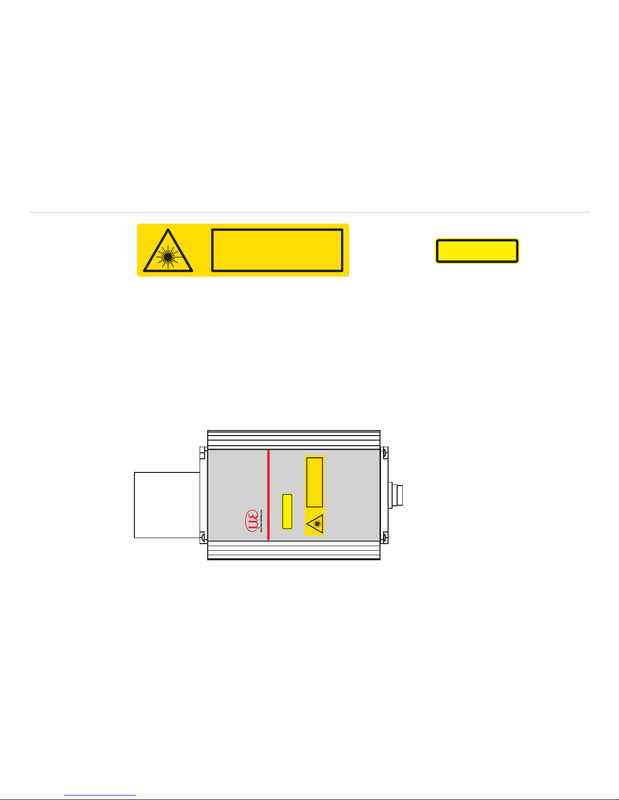
The laser warning labels for Germany have already been applied. Those for other non German-speaking
countries an IEC standard label is included in delivery and the versions applicable to the user‘s country must
be applied before the equipment is used for the first time.
The following warning label is attached on the sensor housing (top side):
Page 10
Page 10
Laser Class
optoNCDT ILR 1181 / 1182
t=0.9 ns f=1.2 GHz
=650 nm
LASER RADIATION
DO NOT STARE INTO BEAM
CLASS 2 LASER PRODUCT
IEC 60825-1: 2007
P1 mW
THIS PRODUCT COMPLIES
WITH FDA REGULATIONS
21CFR 1040.10 AND 1040.11
IEC label Only for USA
i
If both warning labels are disguised in operation mode the user must add additional warning labels.
During operation of the sensor the pertinent regulations according to EN 60825-1 on “radiation safety of laser
equipment“ must be fully observed at all times. The sensor complies with all applicable laws for the manufacturer of laser devices.
Although the laser output is low looking directly into the laser beam must be avoided. Due to the visible light
beam eye protection is ensured by the natural blink reflex.
i
Do not look directly into the laser beam!
Close your eyes or turn away promptly if laser radiation strikes your eyes.
optoNCDT ILR
THIS PRODU T COMPLIES
WTH FDA REGUL TIONS
21CFR 1040.10 AND 1040.11
t=09 ns
f=1.2 Hz
=650 nm
ASER RAD AT ON
DO NOT TARE NTO B AM
CLASS 2 ASER PRODUCT
IEC 60825-1: 2007
P1 mW
Fig. 1 True reproduction of the sensor with its actual location of the warning labels
Page 11

Page 11
Functional Principle, Technical Data
optoNCDT ILR 1181 / 1182
3. Functional Principle, Technical Data
The optoNCDT ILR 1181/1182 is a laser range finder to measure distances from 0.1 m up to 150 m with
pinpoint accuracy. A given target can be clearly identified with the help of a red laser sighting point. In terms
of operating reach, the optoNCDT ILR 1181/1182 performs depending on the reflectance, morphology and
qualities of the target to be measured.
The range finder works based on comparative phase measurement. It emits modulated high-frequency light
which is diffusely reflected back from the target with a certain shift in phase to be compared with a reference
signal. From the amount of phase shift, a required distance can then be determined with millimeter accuracy.
A distance measuring cycle can be triggered in four different ways:
- By sending a command from the PC or another equivalent control unit
- By making appropriate prior parameter settings for the autostart command and applying supply voltage
- By external triggering (in remote-trigger mode)
- Using the autostart trigger function.
For a more detailed description of these four trigger options, see Chap. 7.
Special performance features are:
- Provides high accuracy and great reach under extreme outdoor temperatures.
- Works in a wide range of operating voltages from 10 VDC to 30 VDC from an onboard vehicle supply
point, an industrial direct voltage supply net or a DC power pack.
- Features consistently low power consumption of < 1.5 W (without I
Alarm
).
- Up to 30 m reach for distance measurement, up to 150 m if additional reflectors are mounted onto the
target (depending on reflectance and environmental conditions).
- Visible laser beam for easier sighting.
- RS232/422 interface port for input of measuring functions and commands from, and output of measured
values to, a PC or a laptop.
- Switching output and analog output are separately programmed.
- Switching output with adjustable limit to indicate positive and negative excession of preselectable distance
range window by sighting distance.
- Measured values can be displayed in meters, decimeters, centimeters, feet, inches due to.
- Option for remote triggering of a measurement from an external trigger device.
Page 12
Page 12
Functional Principle, Technical Data
optoNCDT ILR 1181 / 1182
The sensor measures the distance to moving and static targets:
- in the range of 0.1 ... 50 m on diffuse surfaces,
- between 50 m and 150 m on reflectors.
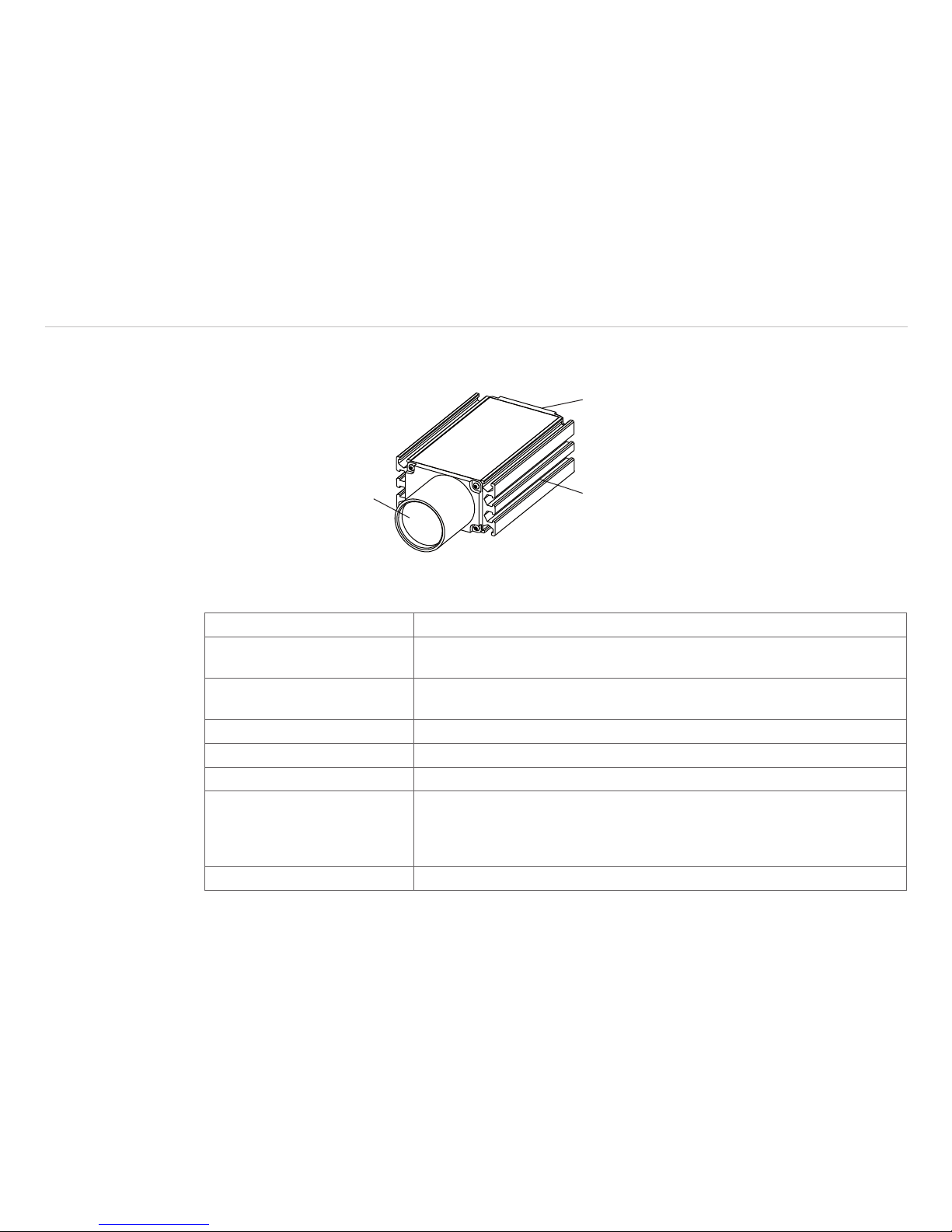
Equalizer tube at front cover
with sender/- receiver optics
Installation slot for
mounting
12-pole M16 flange-mount
connector
Fig. 2 Elements of a sensor
Technical data
Model ILR 1181-30 / ILR 1182-30
Measuring range
1
0.1 … 50 m on natural, diffuse reflective surfaces,
50 m up to max. 150 m on reflection board
Linearity
2
±2 mm (+15°C … +30°C), ±5 mm (-10 °C … +47 °C)
±2 mm ( +59 °F ...+86 °F), ±5 mm ( +14 °F ...+116.6 °F)
Resolution 0.1 mm
Repeatability ≤ 0.5 mm
Response time
1
100 ms ... 6 s (ILR 1181-30) 20 ms ... 6 s (ILR 1182-30)
Laser
acc. to IEC 825-1 / EN 60825
Red 650 nm, laser safety class 2, power output ≤ 1 mW
Beam diameter < 11 mm in 10 m distance
Beam diameter < 35 mm in 50 m distance
Beam diameter < 65 mm in 100 m distance
Laser divergency 0.6 mrad
Page 13

Page 13
Functional Principle, Technical Data
optoNCDT ILR 1181 / 1182
Model ILR 1181-30 / ILR 1182-30
Operating temperature -10 °C … +47 °C ( +14 °F ... to +116.6 °F)
Storage temperature -20 °C … +70 °C (-4 °F ... to +158 °F)
Trigger input Trigger edge and –delay adjustable, Trigger pulse max 24 V
Serial interface RS232 oder RS422, Sensor setup is effected about these interfaces
Digital data rate adjustable, max 38,4 kBaud
Operating mode Individual measurement, external trigger, distance tracking, continuous
measurement
Analog output 4 mA … 20 mA (16 bit DAC), Load ≤ 500 Ohm,
temperature drift max. 50 ppm/K
Switching output Open Collector, HIGH = U
V
– 2 V, LOW < 2 V, rated for loads up to 0.5
A, switching threshold, latitude (width) and hysteresis free selectable,
invertable
Power supply 10 … 30 VDC
Max. power consumption < 1.5 W, no-load state
Connection 12-pole (Binder series 723)
Protection class IP 65
Dimensions 210 mm x 99 mm x 51 mm
Housing material Extruded aluminum profile with powder-coat paint finish
Weight 980 g
1) Conditional on target reflectance, ambient light influences and atmospheric conditions
2) Statistic controller 95 %
Page 14

Page 14
Delivery
optoNCDT ILR 1181 / 1182
4. Delivery
4.1 Supplied Items, Unpacking
1 Sensor optoNCDT ILR 1181-30/1182-30
1 Instruction manual
Check the delivery for completeness and shipping damage immediately after unpacking.
In case of damage or missing parts, please contact the manufacturer or supplier immediately.
You will find optional accessories in appendix, see Chap. A 1.
4.2 Storage
- Storage temperature: - 20 up to +70 °C ( -4 up to +158 °F)
- Humidity: < 65 % (non-condensing)
Page 15

Page 15
Installation
optoNCDT ILR 1181 / 1182
5. Installation
The sensor optoNCDT ILR 1181-30/1182-30 is an optical sensor for measurements with millimeter accuracy.
Make sure it is handled carefully when installing and operating.
5.1 Sensor Mounting
The sensor is be mounted by means of 4 screws type M6 DIN 934 and two groove stones in the installation
slots. The laser beam must be directed perpendicularly onto the surface of the target. In case of misalignment it is possible that the measurement results will not always be accurate.
The sensor will be aligned by a visible laser beam with the target. To align the sensor, please comply with the
“Instructions for Operation“, see Chap. 6.
99 (3.88)
36
(
1.42)
56 (2 2)
7.3
(0.29)
84.4 (3 32)
25.5
(1.0)
51 (2.0)
17.5
(.69)
16
(.63)
ø50
(1.97)
41.9
(1.65)
144 (5.67)
194 (7 64)
M6
slot nuts
Fig. 3 Dimensional drawing sensor, dimensions in mm, not to scale
Page 16
Page 16
Installation
optoNCDT ILR 1181 / 1182
7
( 27)
144 (5.67)
194 (7.64)
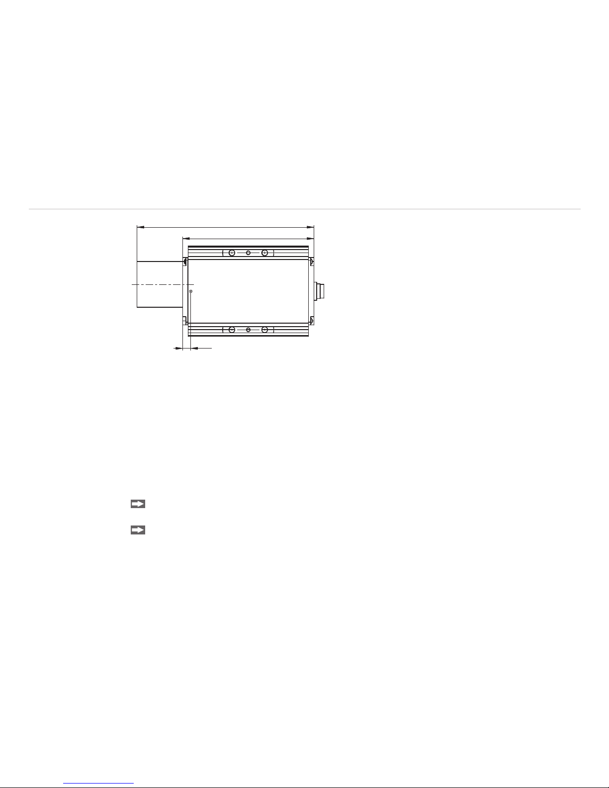
Fig. 4 Offset against zero-edge
The sensor zero-point is located 7 mm behind the outer surface of the front cover or 137 mm before the back
cover outside face respectively. This zero-point has been introduced for constructional design reasons. It can
be compensated with the help of parameter “OF“, see Chap. 7.3.17.
5.2 Reflector Mounting
The sensor measures the distance to moving and static targets:
- in the range of 0.1 ... 50 m on diffuse surfaces,
- between 50 m and 150 m on reflectors (for example reflector film from 3M, Scotchlite Engineer Grade type
I, series 3290).
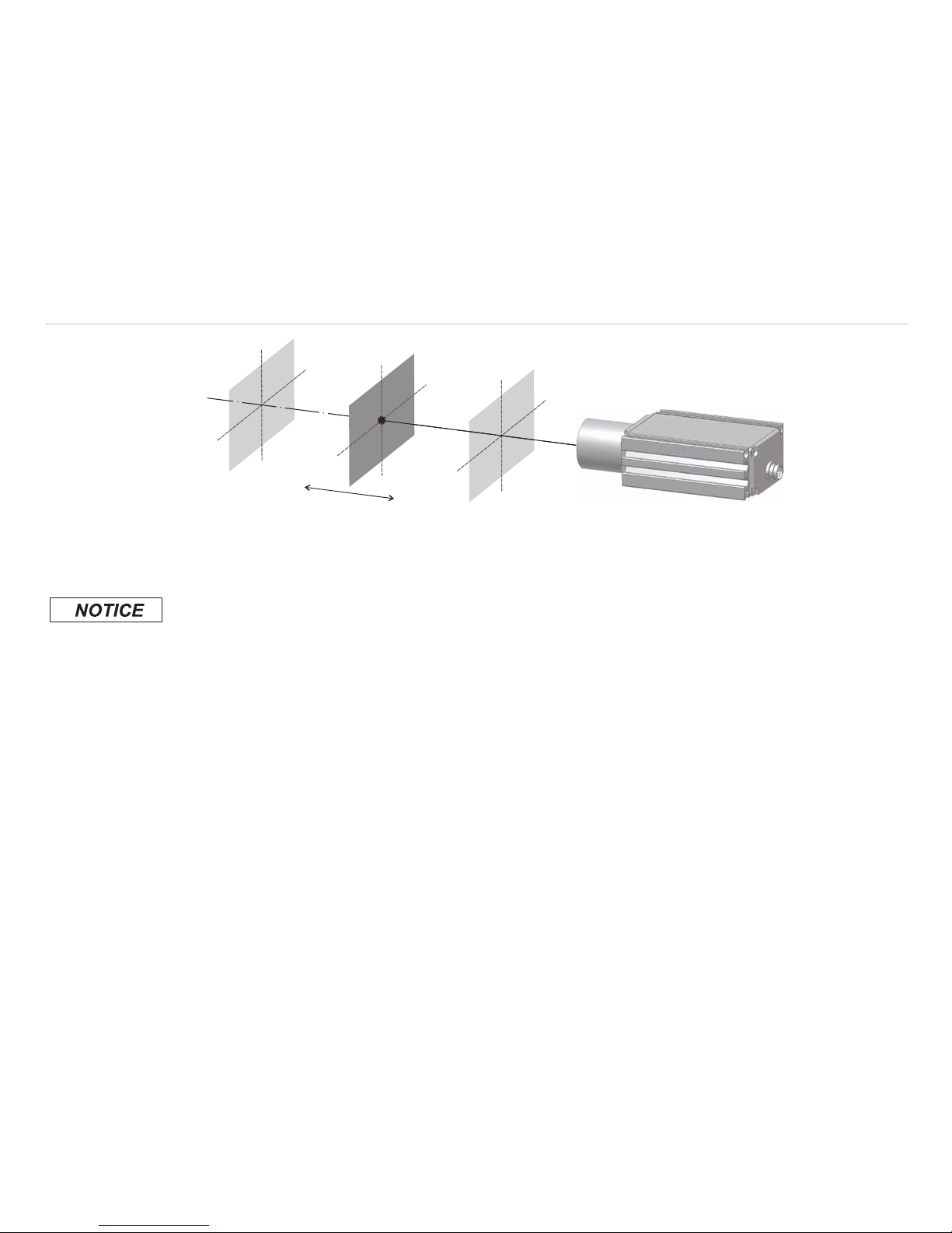
It is possible to align the sensor using the measuring laser. When aligning check as follows:
Move the sensor at a very short distance to the reflector (for example < 1 m). The light spot is aligned in
the centre of the reflector.
Move the sensor with the longest range to the reflector. Check the position of the light spot at the reflec-
tor and set it if necessary.
The light spot must always be in the centre of the reflector whatever the position.
Page 17
Page 17
Installation
optoNCDT ILR 1181 / 1182
Reflector
Reflector
Reflector
Fig. 5 Sensor orientation at reflector film
5.3 Electrical Connections
Located on the back cover is a connector terminal. A 12-pole round-type (flangemount) series 723 connector
from Binder has been selected for this purpose. It is sealed against the casing to comply with IP 65 requirements.
This connector type guarantees optimized screening and a high IP degree. The required counterpart is an
adequate female cable connector with grading ring, available as an optional accessory.
The PC11x cable set with open ends is optionally available.
Bending radius of the supply and output cable PC11x (available as an optional accessory):
- 47 mm (once)
- 116 mm (permanent)
Avoid exposed cable
ends.
So you prevent any
kind of shorts.
The wiring of outputs
with input signals
can damage the
sensor!
Page 18

Page 18
Installation
optoNCDT ILR 1181 / 1182
Pin Color Assignment
ILR 118x-30(01)/RS232 ILR 118x-30(01)/RS422
H
M
G
J
K
A
L
B C
D
E
F
view on solder pin side, 12-pole
female cable connector
A white TxD RX+
B brown RxD RXC green TRIG
D yellow signal I
OUT
(4 ... 20 mA)
E grey --- TXF pink --- TX+
G red
power supply 10 ... 30 VDC
H black alarm/digital switching output
J violet signal ground
K grey/pink n.c.
L red/blue power supply ground
M blue n.c.
Fig. 6 Pin assignment
“Ground“ wires are connected to an internal collective ground point. They provide the reference potential for
all voltage values quoted below.
The limiting values of voltages, load rates and logic levels are in accordance with RS232 and RS422 standard
requirements. All outputs are protected against steady short-circuit currents.
A power supply and output cable extension is possible. One should, however, observe some important rules,
depending on the particular application scenario:
5.3.1 ILR 1181-30
Keep the RxD and TxD data lines as short as possible in all cases, because they tend to have an interference
emitting and interference receiving effect, notably, when in open state. Especially in environments with strong
spurious radiation there may be faults that may in some cases require a reset (turning the sensor off and on
again).
If the RS232 interface communication is not required after parameterization, you should provide for a termination wiring.
Page 19

Page 19
Installation
optoNCDT ILR 1181 / 1182
white
brown
violet
3 kOhm 2.2 nF
TxD
RxD
GND
Fig. 7 Recommended termination wiring for work with open RS232
5.3.2 ILR 1182-30
Extension and termination according to standard requirements.
For correct screening, three essential rules must be followed:
1 For integration with vehicles: Where the attachment point and the reference potential (GND or “-“) have
equal potentials, it may be necessary to electrically isolate the sensor housing, in order to prevent
ground loops.
2 Use screened cables. Extend also the cable screen.
3 Connect the screen to the ground of the power supply on cable end.
U
v
GND
GND
1 2 3
Fig. 8 Correct screening of ILR 1181/1182
Page 20

Page 20
Operation
optoNCDT ILR 1181 / 1182
6. Operation
Protect all cable ends before you turn on the power supply. So you avoid shorts.
Connect cable connections as required for the particular operating mode.
For starting up, a PC with RS232 or RS422 data interface and a terminal program such as the HyperTerminal® are required.
Install the sensor as part of preparative actions in the designated working site, oriented onto the target
and keep it in a stable position. The target to be measured should preferentially have a homogeneous,
white surface.
Reflector
Reflector
Reflector
Fig. 9 Measurement against a reflector
The sensor provides a visible laser beam for greater convenience in alignment. This laser beam can easily
be turned on at the PC. Its visibility is conditional on the amount of ambient light present and on the type of
surface of the target to be measured.
Page 21

Page 21
Operation
optoNCDT ILR 1181 / 1182
6.1 RS232
Initially, RS232 communication interfaces purely functioned as PC communication ports. They have become
the established standard tool for serial data transmission over short cable lengths. With greater transmission
the interface is highly susceptible to interferences, notably, in the vicinity of strong electromagnetic noise
emitters.
Therefore, it should only be used for sensor configuration.
Parameter
- Baud rate: 9.6 kBaud (2.4 / 4.8 / 19.2 / 38.4) - Start/Stop bit: 1
- Data bits: 8 - Handshake: none
- Parity: none - Protocol: ASCII
Properties:
- Maximum input voltage RxD = ±25 V
- Output voltage TxD = 5 V
U
V
GND
2
TxD>>
<<RxD
GND
3
Shield
red/blue
red
violet
brown
white
5
Fig. 10 Diagram of RS232 wiring at 9-pole D-Sub female cable connector
U
V
GND
2
TxD >>
<<RxD
GND
3
Shield
red/blue
red
violet
brown
white
7
Fig. 11 Diagram of RS232 wiring at 25-pole D-Sub female cable connector
i
The RS232 interface is popular in industrial applications. Use an adequate USB TO RS232 converter in
the case of your PC/ notebook is just equipped with USB interfaces.
Page 22

Page 22
Operation
optoNCDT ILR 1181 / 1182
6.2 RS422
For configuration purposes and permanent data transmissions over a greater length, the RS422 can be used.
This type of interface is insusceptible to interference and noise influences and qualifies for industrial use.
Where twisted cable pairs are involved, transmissions lengths up to 1200 m can be handled.
Properties:
- Maximum input voltage RX+, RX- = ±14 V
- Output voltage TX ±2 V, 2 x 50 W load differential
U
V
GND
<<RX+
<<RX TX ->>
TX+>>
wh te
brown
red
red/blue
gray
pink
Fig. 12 Wiring diagram RS422
i
The RS422 interface is popular in industrial applications. Use an adequate USB TO RS422 converter or
a RS422 interface card in the case of your PC/ notebook is just equipped with USB interfaces.
Page 23

Page 23
Operation
optoNCDT ILR 1181 / 1182
6.3 Digital Switching Output
Properties: Open collector
- HIGH = U
V
– 2 V
- LOW < 2 V
- rated for loads up to 0.5 A
- with switching threshold, latitude (width) and hysteresis selectable
U
V
GND
I
L
= 10 ... 500 mA
red
red/blue
black
Fig. 13 Wiring diagram of digital switching output
For example, using the digital switching output, an object which was selected for measurement can be
monitored for excession of a threshold value. To do this, parameter settings for a measurement window are
required. Settings for this window can be made via the three parameters: Alarm Center (AC), Alarm Hysteresis (AH) and Alarm Width, see Chap. 7.3.7 et seq..
The range which will be subject to monitoring begins at AC and ends at AC+AW. Switching transitions can be
set via parameter AH. The logic state of the switching output follows from the mathematical sign of AH. In the
case of a positive AH, the output switches
- with increasing distance:
from LOW to HIGH if the distance is found to be greater than (AC + AH/2).
from HIGH to LOW if the distance is found to be greater than (AC + AW + AH/2)
- with decreasing distance:
from LOW to HIGH if the distance is found to be smaller than (AC + AW - AH/2).
from LOW to HIGH the distance is found to be smaller than (AC - AH/2).
In the case of a negative AH, the output switching pattern will be inverse.
Page 24

Page 24
Operation
optoNCDT ILR 1181 / 1182
AH
AW
AH
HIGH LOW
LOW
HIGH
+AH -AH
Dist.
AC
Fig. 14 Digital switching output behavior with positive and negative hysteresis
Example:
A moving object is assumed to be monitored within a window of 10 m to 11 m with a hysteresis of 0.2 m.
Consecutively you find the parameters AC, AW and AH in dependence on SF:
- AC2 / AH0.2 / AW3 / SF1
- AC2000 / AH200 / AW3000 / SF1000
Distance (m) increases
1.8 1.9 2.0 2.1 2.2 ... 5.0 5.1 5.2
+AH L L L H H H H L L
-AH H H H L L L L H H
Distance (m) decreases
5.2 5.1 5.0 4.9 4.8 ... 2.0 1.9 1.8
+AH L L L L H H H H L
-AH H H H H L L L L H
L = LOW, H = HIGH
How the switching output is to behave on occurrence of an error message (E15, E16, E17, E18) can be defined by making suitable settings under “SE“, see Chap. 7.3.6.
Page 25

Page 25
Operation
optoNCDT ILR 1181 / 1182
6.4 Analog Output
Properties: Current output
- 4 mA...20 mA
- Distance range limits can be set
- Behavior on error report can be preselected: 3 mA or 21 mA
- Load resistance: ≤ 500 Ω against GND
- Accuracy: ±0.15 %
- Max. temperature drift: 50 ppm/K
- Resolution: 16 bit DA-converter
U
V
GND
red
red/blue
yellow
4 ... 20 mA
RL ≤ 500 Ω
Fig. 15 Wiring diagram of analog output
The purpose of the analog output is to allow transmission of analog measured values via a 4 ... 20 mA interface.
The amount of current which is injected into the line of transmission is proportional to the distance measured.
A given range of distances can be selected for transmission via the two parameters Range Beginning (RB)
and Range End (RE), see Chap. 7.3.10, see Chap. 7.3.11.
RE may be greater or smaller than RB.
The amount of injected current can be calculated as follows:
- RE > RB: IOUT [mA] = 4 mA + 16*((Distance - RB) / (RE - RB)) mA
- RE < RB: IOUT [mA] = 20 mA - 16*((Distance - RE) / (RB - RE)) mA
Page 26

Page 26
Operation
optoNCDT ILR 1181 / 1182
Current out of distance range:
Dist. < (RB..RE) Dist. > (RB..RE)
RE > RB 4 mA 20 mA
RE < RB 20 mA 4 mA
On occurrence of an error message (E15, E16, E17, E18), the output current can be matched to 3 mA or
21 mA with the help of parameter SE, see Chap. 7.3.6.
RB>RE
4
3
21
20
SE=2
SE=1
RB<RE
0
Dist.
I
out
[mA]
Fig. 16 Output current diagram for RE > RB and RE < RB
Examples:
The distance of a moving target is to be measured in a range of 2 m up to 6 m. At a distance of 2 m the sensor is to output 4 mA. You find the parameter RB and RE against SF below:
- RB2 / RE6 / SF1
The distance of a moving target is to be measured in a range of 1 m up to 21 m. At a distance of 1 m the sensor is to output 20 mA. You find the parameter RB and RE against SF below:
- RB21000 / RE1000 / SF1000
Page 27

Page 27
Operation
optoNCDT ILR 1181 / 1182
6.5 Trigger Input
Properties:
- Trigger voltage 3 V ... 24 V
- Trigger threshold +1.5 V
- Trigger delay 5 ms + selectable delay time until start of measurement
- Trigger pulse length ≥ 1 ms
- Delay time (trigger delay) selectable from 0 ms to 9999 ms
- Extended trigger function: selectable autostart trigger
GND
red
red/blue
max. 24 V
U
V
green
Fig. 17 Wiring diagram of trigger input
The trigger input is intended for triggering a distance measurement with an external signal that is applied as a
voltage pulse between 3 V and 24 V.
Specify a desired delay time and the pulse flank to be selected for synchronization, see Chap. 7.3.13.
Switch the sensor to trigger mode (DF), see Chap. 7.2.5.
i
Connect the trigger input with +24 V or the ground connection. The input may not remain open defi-
nitely.
NC at +24 V for L-level-trigger
NC at ground for H-level-trigger
Page 28

Page 28
Control Commands
optoNCDT ILR 1181 / 1182
7. Control Commands
7.1 Command Review
The easiest way to trigger and parameterize the sensors is by using a PC with RS232 communication port
and a terminal program, see Chap. 8.. The communications protocol is available in ASCII format.
Before an operating session begins, desired parameter settings can be made in a smart selection procedure
until the measuring module is optimally adapted to the particular measuring site conditions and the measuring job. All valid settings will be preserved on turning the sensor off! They can only be replaced with new
value entries or changed back to their standard values by running an initialization routine.
Command Description
ID Online help to the control commands
DT Starts distance tracking
DS Starts distance tracking 7 m
DW Starts distance tracking on white target at 10 Hz
DX Starts distance tracking on white target at 50 Hz (only ILR 1182-30)
DF Starts remote-triggered single distance measurement (single shot)
DM Starts single distance measurement (single shot)
TP Queries inner temperature
SA Queries / sets floating average value (1...20)
SD Queries / sets output format (dec/hex)
ST Queries / sets time to measure (0...25)
SF Queries / sets scale factor
SE Queries / sets error mode (0, 1, 2)
AC Queries / sets alarm center
AH Queries / sets alarm hysteresis
AW Queries / sets alarm width
RB Queries / sets beginning of range (4 mA)
RE Queries / sets end of range (20 mA)
RM Queries / sets removal of measured value
TD Queries / sets trigger delay
Page 29

Page 29
Control Commands
optoNCDT ILR 1181 / 1182
TM Queries / sets trigger mode
BR Queries / sets baud rate
AS Queries / sets autostart
OF Queries / sets offset
SO Sets current distance as offset
PA Displays all parameter values
PR Resets all parameters to standard values
Fig. 18 Short overview control commands
Command entries are not case-sensitive. This means that small and capital lettering can be used for commands. Any command which is to be sent to the sensor must be terminated by a hexadecimal 0Dh (carriage
return) character.
Where decimal digits are to be entered, they must be separated by period (2Eh).
For command paramater entries, one must distinguish between parameter settings and parameter queries.
Querying is achieved with a command in simple format, for example parameter alarmcenter: AC[Enter]. For
parameter setting, a new value must be added after the command with no delimitation sign in between, for
example: AC20.8[Enter]. In the given example, the alarm center will be set to 20.8.
Page 30

Page 30
Control Commands
optoNCDT ILR 1181 / 1182
7.2 Modes
i
The sign ESC (1Bh) finishes the data output. Now the sensor waits for a new command.
7.2.1 DT......Distancetracking
Essential input parameters: SA, SD, SE, SF, ST, OF
Effect on: RS232/RS422, digital switching output, analog output
- Distance measurement at different kinds of surfaces (varying reflectance).
- Permanent evaluation of the sensitive laser radiation.
changing reflectance: longer measuring time
sudden jumps in distance: longer measuring time
The minimum time to measure is 160 ms, the maximum time is 6 s. If the measuring signal fails to reach a
specified quality within six seconds, an error message is output.
The time to measure may also be limited by setting the ST parameter to a desired value.
7.2.2 DS ...... 7 m Distance Tracking
Essential input parameters: SA, SD, SE, SF, ST, OF
Effect on: RS232/RS422, digital switching output, analog output
- Distance measurement at different kinds of surfaces at close range up to 7 m
- Higher measurement rate compared to DT measuring mode.
- Within the range from 0.1 m to 0.5 m, measuring accuracy is restricted.
Measuring time (time to measure) can be limited via ST parameter settings.
Page 31

Page 31
Control Commands
optoNCDT ILR 1181 / 1182
7.2.3 DW......Distance Tracking with Cooperative Target (10 Hz)
The command is only relevant for the ILR 1181.
Essential input parameters: SA, SD, SE, SF, OF
Effect on: RS232/RS422, digital switching output, analog output
- Performs at a steady measuring rate of 10 Hz.
- Stable measuring values only with a white target board at the target.
- No sudden jumps in distance > 16 cm.
7.2.4 DX......Distance Tracking with Cooperative Target
The command is only relevant for the ILR 1182.
Essential input parameters: SA, SD, SE, SF, OF
Effect on: RS232/RS422, digital switching output, analog output
- Performs at a steady measuring rate of 50 Hz.
- Stable measuring values only with a white target board at the target.
- Homogeneous motions with maximum 4 m/s.
- High rate of measurement, included preceding measuring values in the process to calculate a currently
measuring value.
- No sudden jumps in distance >16 cm.
7.2.5 DF......Distance Measurement with External Trigger
Essential input parameters: SD, SE, SF, ST, OF, TD
Effect on: RS232/RS422, digital switching output, analog output
- Preparation for the single measurement, triggered by an external trigger pulse.
Initially, after selecting this mode, the operator does not receive any response. As soon as the trigger pulse
has been detected, the sensor will send data and switches the digital and/or the analog output.
The Settings for the trigger delay (delay) and the trigger flank can be defined via parameter TD, see Chap.
7.3.13.
Page 32

Page 32
Control Commands
optoNCDT ILR 1181 / 1182
7.2.6 DM......Distance Measurement
Essential input parameters: SD, SE, SF, ST, OF
Effect on: RS232/RS422, digital switching output, analog output
- Triggers a single measurement (single shot).
7.3 Parameter
7.3.1 TP.......Internal Temperature
TP queries the value of the inner sensor temperature in °C.
i
In tracking mode, the inner temperature may exceed the surrounding temperature level by as much as
10 K.
7.3.2 SAx......Display/Set Average Value
Standard setting: N = 1
SA allows you to calculate a floating average value from 1 to 20 measured values.
MW (k)
k=1
N
N
M =
av
∑
Fig. 19 Formula for the floating average value
MW = Measuring value
N = Quantity
k = Current index
M
av
= Average value
Page 33

Page 33
Control Commands
optoNCDT ILR 1181 / 1182
Method
Every new measuring value is added, the first (oldest) measuring value is taken out of the averaging.
Example with N = 7:
.... 0 1 2 3 4 5 6 7 8
gets to Average value n
.... 1 2 3 4 5 6 7 8 9
gets to Average value n + 1
7.3.3 SDd......Display/Set Display Format
Standard setting: d
SD switches between decimal (d) and hexadecimal (h) output format of measured value data. SD affects all
commands that output a distance value.
A hexadecimal output value is calculated from a given measured distance value (in mm), multiplied by the
scale factor SF.
Negative distance values are output in two’s complement notation.
Example:
Distance = 4.996 m, SF1 dec: 4.996 hex: 001384 (= 4996 mm × SF1)
Distance = 4.996 m, SF10 dec: 49.960 hex: 00C328 (= 49960 = 4996 mm × SF10)
7.3.4 STx......Display/Set Measuring Time
Standard setting: 0
Measuring time is directly conditional on the selected measuring mode. As a general rule, one may say: the
poorer the surface reflectance of a selected target, the longer the sensor will take to determine a given distance with specified accuracy. For example, if error message E15 is output because of poor reflectance and
insufficient time to measure, this latter setting must be increased.
- Value range ST: 0 ... to 25
- The greater the time setting is the more time will be available for measurement and the lower the resulting
measuring rate.
- An exception therefrom is zero-value. In this case, the sensor automatically picks the smallest possible
time value for measurement!
- The sensor comes factory-set with ST = 0.
- ST is effective in the DT, DS, DF and DM modes.
2+3+4+5+6+7+8
7
3+4+5+6+7+8+9
7
Page 34

Page 34
Control Commands
optoNCDT ILR 1181 / 1182
The measuring time setting option allows also the modifying of the measuring rate, for example, in order to
restrict the data volume or for synchronization purposes.
Measuring time can only be set as an approximate value, because the underlying principle of measurement
is subject to certain variances that cannot be accounted for:
DT measuring mode > measuring time approximately ST x 240 ms (except ST = 0)
DS measuring mode > measuring time approximately ST x 150 ms (except ST = 0)
Example:
The target distance is 25 m, but the target’s reflectance is not ideal. With a measuring time setting of ST 2,
E15 will be output following measurement. The user must increase the measuring time in this case!
i
One should work in DW or DX mode where stable measuring times are required.
7.3.5 SFx.x.....Display/Set Scale Factor
Standard setting: 1
SF multiplies a calculated distance value with a user-selectable factor for changes in resolution or outputs in
a different unit of measure. The scale factor may also be negative.
Scale factor Resolution Output Unit of measure
SF1 1 mm 02.693 m
SF10 0.1 mm 26.931 dm
SF1.0936 0.01 yard 02.945 yard
SF3.28084 0.01 feet 08.835 feet
SF0.3937 1 inch 01.060 100 inch
SF-1 1 mm -02.693 m
Fig. 20 Examples of scale factor
i
Following a change in the scale factor, the settings for digital and/ or analog output and offset must be
matched accordingly!
Page 35

Page 35
Control Commands
optoNCDT ILR 1181 / 1182
7.3.6 SEx......Display/Set Error Mode
Standard setting: 1
SE allows you to configure how the digital switching output (alarm) and/or the analog output is to behave on
occurrence of an error message (E15, E16, E17, E18).
Depending on the particular sensor application, different reactions to an error message are possible.
Available selection options:
SE Digital switching output (ALARM) Analog output (I
OUT
)
0 ALARM of latest valid measurement I
OUT
of latest valid measurement
1 AH: ALARM = LOW
-AH: ALARM = HIGH
RE > RB: I
OUT
= 3 mA
RE < RB: I
OUT
= 21 mA
2 AH: ALARM = HIGH
-AH: ALARM = LOW
RE > RB: I
OUT
= 21 mA
RE < RB: I
OUT
= 3 mA
Fig. 21 Digital switching output and analog output
7.3.7 ACx.x.....Display/Set ALARM Center
Standard setting: 0.1
AC sets the beginning of the distance range, for which the switching output will be turned active. The length
of this active range can be set using the AW parameter.
AC must be selected in keeping with the currently set SF scale factor (see Chap. 6.3 Digital switching output).
7.3.8 AH......Display/Set ALARM Hysterese
Standard setting: 0.001
AH allows you to make parameter settings for the switching hysteresis at the beginning and the end point of
the active range of the switching output.
- Set AH so it is properly matched to the currently valid scale factor (SF).
- The mathematical sign of AH affects the setting of an active state logic level:
Positive sign (“+”): active range is HIGH-active.
Negative sign (“-“): active range is LOW-active.
No sign setting means positively-signed, see Chap. 6.3.
Page 36

Page 36
Control Commands
optoNCDT ILR 1181 / 1182
7.3.9 AWx.x......Display/Set ALARM Width
Standard setting: 100
- AW sets the length of the active range, beginning at AC.
- Set AW settings in agreement with the currently valid SF scale factor.
- AW is always equal or greater than “0” (zero).
- AW is always equal or greater than |AH| (the amount of AH), see Chap. 6.3.
7.3.10 RBx.x.....Display/Set Distance of Lout=4mA
Standard setting: 0.1
RB (Range Beginning) corresponds to the starting point of the distance range that is provided at the analog
output.
- A distance value = RB will generate a current I
OUT
of 4 mA.
- Set RB in agreement with the currently valid SF scale factor.
- RB can be greater or smaller!
- Beyond the range that was set via RB and RE, the applied current will be that of the next limiting value.
In the event of a fault, the output value will correspond to the current that was set via parameter SE, see
Chap. 7.3.6.
7.3.11 REx.x.....Display/Set Distance of Lout=20mA
Standard setting: 30
RE (Range End) corresponds to the end point of the distance range that is provided at the analog output.
- A distance value = RE will generate a current I
OUT
of 20 mA.
- Set RE in agreement of the scale factor SF.
- RE can be greater or smaller as RB!
- Beyond the range that was set via RB and RE, the applied current will be that of the next limiting value.
- In the event of a fault, the output value will correspond to the current that was set via parameter SE, see
Chap. 7.3.6.
7.3.12 RMx y.y z......Remove Measurement
Standard setting: 0 0 0
RM is intended to facilitate settings for a range of expected distance values. Values which are found to be outside of this expected range will be corrected until matching the most recently valid measuring values.
The use of RM
parameter settings
should be restricted
to suitable applications only. Improper
use of this parameter may create
safety hazards!
Page 37

Page 37
Control Commands
optoNCDT ILR 1181 / 1182
RM is only effective in DT mode.
It consists of three parameters which are separated by space (20
hex
).
X Designates the number of preceding measuring values that will be evaluated in the case of non-con-
forming measurement. A maximum of ten preceding measured values can be evaluated.
Y Defines the range of permissible values. If this range is exceeded in negative or positive direction, the
respective measuring value will be corrected accordingly.
Z Stands for the number of values that are out of the permissible value range; in the event of out-of-toler-
ance values arriving in succession, the most recently corrected value will be included in the correction
process for the next out-of-tolerance value.
The maximum allowed number of out-of-tolerance values is 100.
Example:
- x = 3
- 2y = 0.1
- z = 1
9.83 (.387)
9.85
(.388)
9.88
(.389)
10 (.393)
9.89
(.389)
9.85
(.388)
9.86
(.388)
9.88
(.389)
9.75 (.384)
9.77
(.385)
9.70 (.382)
9.75 (.384)
9.80 (.386)
9.85 (.388)
9.90 (.39)
9.95 (.392)
10.00 (.393)
10.05 (.396)
123456789 10
Ist-Measurement Korr. run Limit
x
x
z
2y
Fig. 22 Correction of measuring value
Page 38

Page 38
Control Commands
optoNCDT ILR 1181 / 1182
7.3.13 TDxy......Display/Set Trigger Delay, Trigger Level
Standard setting: 0 0
TD sets up solely the behavioral configuration of the remote trigger input (DF mode, see Chap. 7.2.5).
TD consists of two parameters which are separated by space (20
hex
):
- the delay time, and
- trigger flange.
X corresponds to the delay in time from the arrival of a trigger signal to the start of a measurement.
Delay settings may range from 0 to 9999 ms.
Y 0 for HIGH > LOW transition
1 for LOW > HIGH transition
Example:
TD1000_0[Enter]
In the given example, the delay time was set to 1000 ms and the trigger flank to “falling type” (HIGH to LOW
transition).
7.3.14 TMx y......Display/Set Trigger Mode, Trigger Level
Standard setting: 0 1
TM provides parameter the setting option for the auto-start trigger function which allows external triggering of
the auto-start command that was set via parameter AS.
Triggering is accomplished via the external trigger input. All starting modes which are selectable via AS can
be launched and stopped by external triggering. These are: DS/DT/DW/DX/DF/DM/TP/LO/ID.
TM consists of two parameters which are separated by space (20
hex
).
x
0 ... trigger function turned off
1 ... trigger function turned on
y
0 ... measurement is triggered on trigger line at L-level (HIGH > LOW transition)
1 ... measurement is triggered on trigger line at H-level (LOW > HIGH transition)
i
The trigger input must be located on a defined level about +24 V or ground.
Page 39

Page 39
Control Commands
optoNCDT ILR 1181 / 1182
Examples:
a) ASDT
TM1 1
Trigger signal = H > DT is performed
Trigger signal = L > DT is stopped
HIGH
LOW
DT on
DT off
t
b) ASDM
TM1 0
Trigger signal = H > no change in state
Trigger signal = L > DM active, that means, one measurement is triggered
HIGH
LOW
DM on
DM off
t
7.3.15 BRx......Display/Set Baud Rate
Standard setting: 9600
Available baud rate BR settings are: 2400, 4800, 9600, 19200, 38400.
Faulty entries will be rounded to the nearest baud rate.
A fixed data format of eight data bits, with no parity and one stop bit is used.
i
After a change in baud rate setting, the communicating counterpart must also be set to the new baud
rate.
Page 40

Page 40
Control Commands
optoNCDT ILR 1181 / 1182
7.3.16 AS....Display/Set Autostart Command
Standard setting: ID
AS (autostart) defines which function will be carried out when power becomes available to the sensor. Possible entries are those delivering a measuring value on the output side, an ID command and the command
for turning the laser on (LO).
For example, if ASDT has been parameterized, the sensor will begin with distance tracking on turning on
power.
Possible versions: DT/DS/DW/DX/DF/DM/TP/LO/ID
7.3.17 OFx.x.....Display/Set Distance Offset
Standard setting: 0
With the help of OF (offset) define a zero-point for his/her application. For details on the position of the module’s zero-point, see Chap. 5.
- OF must be selected so it is properly matched to the currently valid scale factor setting (SF).
- OF may also take on negative values.
7.3.18 SO......Set Current Distance to Offset
SO performs a distance measurement and saves the measured reading as an offset value with inverted mathematical sign (OF).
Result: (offset = - distance)
Page 41

Page 41
Control Commands
optoNCDT ILR 1181 / 1182
7.3.19 PA......Display Settings
PA lists all parameters in a table.
Example:
average value[SA] 1
display format[SD] d
measure time[ST] 0
scale factor[SF] 1
error mode[SE] 1
ALARM center[AC] 20
ALARM hysterese[AH] 0.1
ALARM width[AW] 10
distance of Iout=4mA [RB] 15
distance of Iout=20mA [RE] 25
remove measurement [RM] 0 0 0
trigger delay, trigger level[TD] 0 0
trigger mode, trigger level[TM] 0 1
baud rate[BR] 9600
autostart command[AS] ID
distance offset[OF] 0
Page 42

Page 42
Control Commands
optoNCDT ILR 1181 / 1182
7.3.20 PR......Reset Settings
PR resets all parameters(except for baud rate) to their standard settings.
average value[SA] 1
display format[SD] d
measure time[ST] 0
scale factor[SF] 1
error mode[SE] 1
ALARM center[AC] 0.1
ALARM hysterese[AH] 0.001
ALARM width[AW] 100
distance of Iout=4mA [RB] 0.1
distance of Iout=20mA [RE] 30
remove measurement [RM] 0 0 0
trigger delay, trigger level[TD] 0 0
trigger mode, trigger level[TM] 0 1
baud rate[BR] 9600
autostart command[AS] DT
distance offset[OF] 0
Page 43

Page 43
Hyperterminal
optoNCDT ILR 1181 / 1182
8. Hyperterminal
You can receive data and configure the controller through the RS232 interface with the Windows HyperTerminal®. All you need is a free COM port (for example COM1) on your PC and the commands described in the
foregoing chapters.
i
The RS232 interface are popular in industrial applications. Use an adequate USB TO RS232 converter,
in the case of your PC/notebook is just equipped with USB interfaces.
Preparation Measuring
Connect your controller to a free COM port of the host computer.
Start the program HyperTerminal® (Menu Start > Programs > Accessory > Communication >
HyperTerminal)
Type in the name of the connection and click on the OK button.
Fig. 23 Connection establishment with the program HyperTerminal®
Select the interface and click on the OK button.
Page 44

Page 44
Hyperterminal
optoNCDT ILR 1181 / 1182
Fig. 24 Definition of the serial interface
Fig. 25 Definition of the serial interface
Define the following interface parameters:
Baud rate: 9.600 Baud
Data format: 8 Data bits
Parity: None
Start/Stopbit: 1
Flow control: No
Click on the OK button.
Type the command ID and press the button EN-
TER.
The sensor reads out the commands for the distance
measuring cycle respectively the prior parameter settings, see Fig. 26. With pressing the ESC-button the data
output will be finished and the sensor waits for further
instructions.
Page 45

Page 45
Hyperterminal
optoNCDT ILR 1181 / 1182
Fig. 26 User interface in terminal operation
i
A currently entered command will only be displayed if “Local echo“ is enabled. This function can be ac-
cessed via file menu File > Properties > Settings > ASCII Setup.
Save finally, unless performed earlier, the current hyperterminal configuration. For more convenience
you don’t have to reconfigure the interface for each new hyperterminal session.
Page 46

Page 46
Online Help Tool
optoNCDT ILR 1181 / 1182
9. Online Help Tool
Once communication has been established with a PC (as described above), an online help tool can be called
up by triggering an ID [Enter] or id [Enter] command at the keypad. Its purpose is to support work with
distance measurement and parameterization commands. [Enter] corresponds to hexadecimal 0D
hex
(carriage
return).
DT[Enter] distancetracking
DS[Enter] distancetracking 7 m
DW[Enter] distancetracking with cooperetive target (10 Hz)
DX[Enter] distancetracking with cooperetive target (50 Hz)
DF[Enter] distance measurement with external trigger
DM[Enter] distance measurement
TP[Enter] internal temperature [°C]
SA[Enter] / SAx[Enter] display/set average value [1..20]
SD[Enter] / SDd[Enter] display/set display format [d/h]
ST[Enter] / STx[Enter] display/set measure time [0..25]
SF[Enter] / SFx.x[Enter] display/set scale factor
SE[Enter] / SEx[Enter] display/set error mode [0/1/2]
0..Iout=const., ALARM=const.
1..Iout: 3 mA @RE>RB, 21 mA @RE<RB,
ALARM: OFF@AH>0, ON@AH<0
2..Iout: 21 mA @RE>RB, 3mA @RE<RB,
ALARM: ON@AH>0, OFF@AH<0
AC[Enter] / ACx.x[Enter] display/set ALARM center
AH[Enter] / AHx.x[Enter] display/set ALARM hysterese
AW[Enter] / AWx.x[Enter] display/set ALARM width
RB[Enter] / RBx.x[Enter] display/set distance of Iout=4 mA
RE[Enter] / REx.x[Enter] display/set distance of Iout=20 mA
RM[Enter] / RMx y.y z[Enter] remove measurement
TD[Enter] / TDx y[Enter] display/set trigger delay [0..9999 ms] trigger level [0/1]
TM[Enter] / TMx y[Enter] display/set trigger mode [0/1] trigger level [0/1]
BR[Enter] / BRx[Enter] display/set baud rate [2400..38400]
Page 47

Page 47
Troubleshooting
optoNCDT ILR 1181 / 1182
AS[Enter] / ASd[Enter] display/set autostart command [DT/DS/DW/DX/DF/DM/TP/LO/ID]
OF[Enter] / OFx.x[Enter] display/set distance offset
SO[Enter] set current distance to offset
(offset = - distance)
PA[Enter] display settings
PR[Enter] reset settings
10. Troubleshooting
Code Description Action for removal
E15 Excessively poor reflexes; Distance sensor
(Front edge) against target < 0.1m
Use target board,
increase distance between sensor and target.
E16 Excessively strong reflexes Use target board.
E17 Too much steady light (for example sun) Reduce ambient light at target;
reflecting objects remove or cover.
E18 Only in DX mode (50 Hz): too much differ-
ence between measured and pre-calculated
value
Check path from distance meter to target being
measured for obstacles.
E19 Only in DX mode (50 Hz):Target motion
speed > 10 m/s
Reduce motion speed of target respectively of the
sensor.
E23 Temperature below -10 °C Provide ambient temperature > -10 °C
E24 Temperature above +60 °C Provide ambient temperature < +60 °C
E31 Faulty EEPROM checksum,
hardware error
Service required if fault occurs repeatedly
--> reship the sensor for repair.
E51 Failure to set avalanche voltage of diode laser
1. straylight or
2. hardware error
1. Check ambient light radiation; limit ambient light
2. Service required --> reship the sensor for repair.
E52 Laser current too high / laser defective --> Reship the sensor for repair, contact technical
support
Page 48

Page 48
Cleaning
optoNCDT ILR 1181 / 1182
E53 One or more parameters in the EEPROM not
set (Consequence: Division by 0)
1. Parameter SF examine (SF must be unequal 0)
2. Contact technical support --> reship the sensor
for repair.
E54 Hardware error (PLL) Contact technical support --> reship the sensor for
repair.
E55 Hardware error Contact technical support --> reship the sensor for
repair.
E61 Used parameter is inadmissible, invalid com-
mand sent
Check control software commands.
E62 1. Hardware error
2. wrong value in interface communication
(Parity error SIO)
Check external software parity setting.
E63 SIO overflow Check time of emitted signals in application soft-
ware; integrate delay on transmission if necessary.
E64 Framing-Error SIO Data format of the serial interface examine (8N1)
11. Cleaning
Remove dust from optical surfaces (transmitter and receiver optics) with a blower brush.
Do not use cleaners that contain organic solvents, when wiping optical surfaces down
Contact the manufacturer in the case of stubborn contamination or soiling.
Avoid the use of any kind of solvents to clean the sensor.
> Damage of the sensor
Do not open the device. Do not loose any screw at the sensor
> Damage of the sensor
Page 49

Page 49
Warranty
optoNCDT ILR 1181 / 1182
12. Warranty
All components of the device have been checked and tested for perfect function in the factory. In the unlikely
event that errors should occur despite our thorough quality control, this should be reported immediately to
MICRO-EPSILON. The warranty period lasts 12 months following the day of shipment. Defective parts, except
wear parts, will be repaired or replaced free of charge within this period if you return the device free of cost to
MICRO-EPSILON.
This warranty does not apply to damage resulting from abuse of the equipment and devices, from forceful
handling or installation of the devices or from repair or modifications performed by third parties. No other
claims, except as warranted, are accepted. The terms of the purchasing contract apply in full.
MICRO-EPSILON will specifically not be responsible for eventual consequential damages.
MICRO-EPSILON always strives to supply the customers with the finest and most advanced equipment.
Development and refinement is therefore performed continuously and the right to design changes without
prior notice is accordingly reserved.
For translations in other languages, the data and statements in the German language operation manual are
to be taken as authoritative.
13. Service, Repair
In the event of a defect on the sensor please send
us the affected parts for repair or exchange stating
the conditions in which it has operated (applications, conditions and environmental conditions).
In the case of faults the cause of which is not clearly identifiable, the entire measuring system must be
sent back to:
MICRO-EPSILON MESSTECHNIK
GmbH & Co. KG
Königbacher Str. 15
94496 Ortenburg / Germany
Tel. +49 (0) 8542/ 168-0
Fax +49 (0) 8542 / 168-90
info@micro-epsilon.de
www.micro-epsilon.com
Page 50

Page 50
Decommissioning, Disposal
optoNCDT ILR 1181 / 1182
14. Decommissioning, Disposal
Disconnect the power supply and output cable on the sensor.
Incorrect disposal may cause harm to the environment.
Dispose of the device, its components and accessories, as well as the packaging materials in compli-
ance with the applicable country-specific waste treatment and disposal regulations of the region of use.
Page 51

Page 51
Decommissioning, Disposal
optoNCDT ILR 1181 / 1182
Appendix
A 1 Accessories
PC11xx Power supply-/ output cable; 2
m up to 30 m length (subject to
order)
PC1100-3/RS232
Power supply-/output cableRS232, 3 m length
FC1100 Female
cable connector
Female cable connector for
ILR11xx
Page 52

Page 52
Decommissioning, Disposal
optoNCDT ILR 1181 / 1182
ILR-PG118x
Protective glass
Protective glass for ILR118x
ILR-MP118x
Mounting plate
for ILR118x
Mounting plate for ILR118x
ILR-MT118x
Mounting
brackets
Mounting brackets; with M6
screws
Contents: 2 pieces
Page 53

Page 53
Decommissioning, Disposal
optoNCDT ILR 1181 / 1182
ILR-MTN118x
Slot nuts
2 nuts for mounting sensors of
ILR118x series, incl. fastening
screws
A 2 Factory Setting
Parameter Setting
SA 1
SD d
ST 0
SF 1
SE 1
AC 0.1
AH 0.001
AW 100
RB 0.1
i
At the parameters AC, AH, TD, TM, RM the values are to separate by space.
Decimal tag is a dot (2E
hex
).
The command PR reset all parameters with excepting the baud rate to the standard settings.
Parameter Setting
RE 30
TD 00
BR 9600
AS DT
OF 0
TM 01
RM 000
Adress Slave no value
Page 54

MICRO-EPSILON MESSTECHNIK GmbH & Co. KG
Königbacher Str. 15 · 94496 Ortenburg / Germany
Tel. +49 (0) 8542 / 168-0 · Fax +49 (0) 8542 / 168-90
info@micro-epsilon.de · www.micro-epsilon.com
X9751184-A051116HDR
*X9751184-A05*
MICRO-EPSILON MESSTECHNIK
 Loading...