

Page 1

4 channel measuring amplifier GSV-4
GSV-4BT
GSV-4USB
Operating instructions
Updated: 02.02.2018
ME-Meßsysteme GmbH
Neuendorfstr. 18a Tel.: +49 3302 89824 60 Mail: info@me-systeme.de
16761 Hennigsdorf Fax: +49 3302 89824 69 Web: www.me-systeme.de 1
Page 2

Page 3

Contents
Inhaltsverzeichnis
Straingage measuring amplifier GSV-4USB.......................................................................................4
Description.......................................................................................................................................... 4
Dimensions.........................................................................................................................................5
Technical data....................................................................................................................................6
Connection assignment.................................................................................................................... 7
Strain Gage measuring amplifier GSV-4BT......................................................................................18
Description........................................................................................................................................18
Dimensions....................................................................................................................................... 19
Technical data..................................................................................................................................20
Wiring diagram.................................................................................................................................21
Technical data GSV-4BT M12.......................................................................................................25
Switch configuration GSV-4BT M12............................................................................................26
Measurement resolution................................................................................................................28
Order variants GSV-4BT.................................................................................................................29
Programming / configuration............................................................................................................ 30
Scaling of measured values..........................................................................................................30
Measuring range 2.0 mV/V............................................................................................................30
Measuring range 10.0 mV/V.........................................................................................................30
Measuring range 0.0 to 5 V............................................................................................................31
Measuring range 0.0 to 10 V.........................................................................................................31
Measuring range PT1000...............................................................................................................31
Measuring range K thermocouple cable.....................................................................................32
Commands for configuration........................................................................................................32
List of commands...........................................................................................................................32
Description of commands.............................................................................................................34
Protocol for measured values....................................................................................................... 37
Protocol for commands.................................................................................................................37
Protocol for responding to commands.......................................................................................37
Digital IOs..........................................................................................................................................39
Analogue input................................................................................................................................. 43
CAN bus.................................................................................................................................................44
Protocol for measured values....................................................................................................... 44
Protocol for commands.................................................................................................................44
Protocol for responding to commands.......................................................................................44
Configuring the CAN-ID..................................................................................................................45
Data frequency and filter................................................................................................................46
Analogue filter.................................................................................................................................. 46
Digital filter........................................................................................................................................ 46
Annex...................................................................................................................................................... 48
Connection figures for GSV-4BT SD and GSV-4BT LD.............................................................48
Changelog......................................................................................................................................... 52
ME-Meßsysteme GmbH
Neuendorfstr. 18a Tel.: +49 3302 89824 60 Mail: info@me-systeme.de
16761 Hennigsdorf Fax: +49 3302 89824 69 Web: www.me-systeme.de 3
Page 4
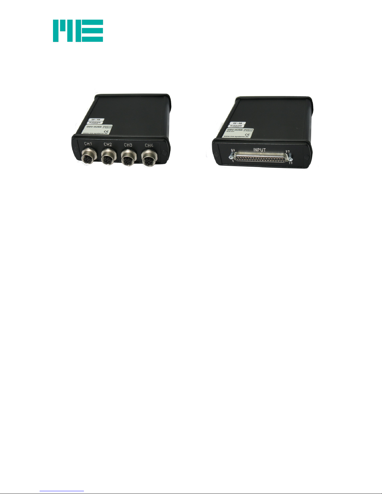
Straingage measuring amplifier GSV-4USB
GSV-4USB M12
Front view sensor connection
GSV-4USB SUB-D37
Front view sensor connection
Description
This 4-channel measuring amplifier for sensors with strain gauges is equipped with a USB
interface. The voltage is supplied via the USB port at the back of the measuring amplifier.
The measuring amplifier can be delivered with an SUB-D37 connection or with 4x M12 ports.
The measuring amplifier has eight digital inputs and outputs.
On the backside SubD25 socket, strain gauge full-bridges and half-bridges 120 Ohm up to 1
kOhm as well as PT1000 temperature sensors and 1000 Ohm single grid strain gages or
voltages 0 ... 5V can be connected.
The front-end M12 socket is configured by default for strain gauge full-bridge connections
and for voltage inputs 0 ... 5V and 0 ... 10V.
ME-Meßsysteme GmbH
Neuendorfstr. 18a Tel.: +49 3302 89824 60 Mail: info@me-systeme.de
4 16761 Hennigsdorf Fax: +49 3302 89824 69 Web: www.me-systeme.de
• 4-channels
• Power supply via USB port
• Inputs for Straingage / 0–10 V / PT1000
• Measurement ranges 2 mV/V / 10 mV/V
• Straingage quarter / half / full bridges
• 8 digital inputs / outputs
• Data rate 0 Hz–500 Hz
Page 5
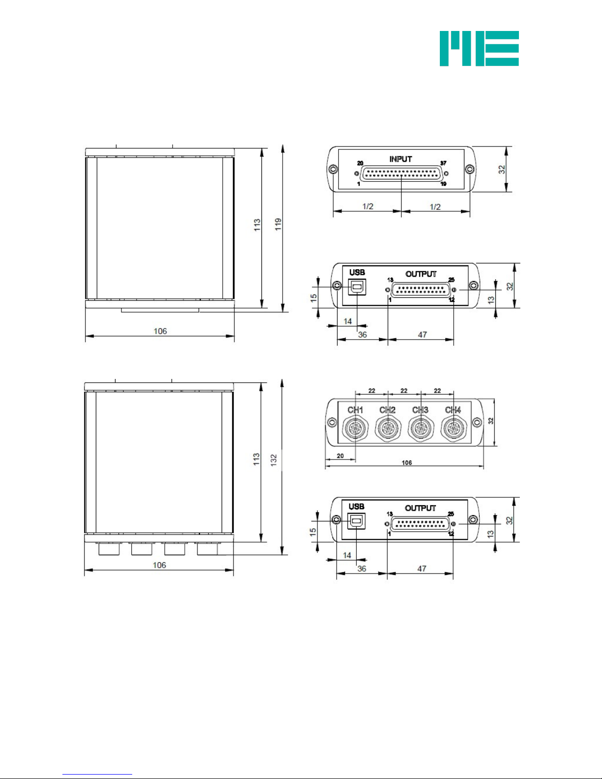
Dimensions
Figure 2: Dimensions GSV-4USB M12
ME-Meßsysteme GmbH
Neuendorfstr. 18a Tel.: +49 3302 89824 60 Mail: info@me-systeme.de
16761 Hennigsdorf Fax: +49 3302 89824 69 Web: www.me-systeme.de 5
Figure 1: Dimensions GSV-4USB SUB-D37
Page 6
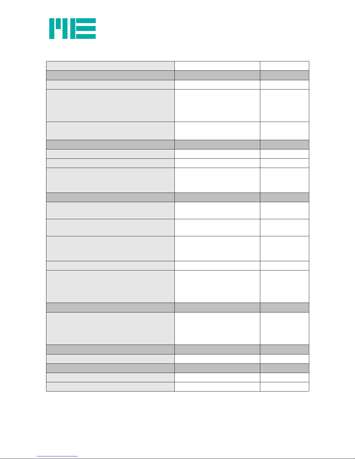
Technical data
Accuracy class 0.05 %
Inputs
Resolution 16 Bit
Straingage inputs
Full bridge
Half bridge
Quarter bridge
89-5000
89-5000
120 / 350 / 1000
Ohm
Ohm
Ohm
Common mode rejection
at 60 Hz common-mode signal
95–110 dB
Measurement frequencies
Data frequency 0 – 500 Hz
Sampling frequency 1.92 MHz
Cut-off frequency
analogue
digital
450
Notch filter
Hz
Hz
Outputs
Bridge supply voltage
Current load capacity
2.5
30
Volt
mA
Fixed voltage output
Current load capacity
5
20
V
mA
Switching outputs/inputs
I/O 1-8
Current load capacity:
TTL level
5 (active High)
5
V
mA
Interface USB 1.1, USB 2.0 compatible
Supply voltage
Nominal range
Isolation voltage
Current consumption
4.5...5.5 via USB port
1000
< 200
V DC
Vrms
mA
Temperature range
Nominal temperature range
Storage temperature range
Zero point drift
Sensitivity drift
-10…+65
-40…+85
< 0.05
< 0.01
°C
°C
%/10°C
%/10°C
Dimensions
L x W x H 106 x 119 (132) x 32 mm x mm x mm
Protection type / Weight
Protection type IP40
Weight GSV-4USB SUB-D37 239 g
Table 1: Technical data GSV-4USB
ME-Meßsysteme GmbH
Neuendorfstr. 18a Tel.: +49 3302 89824 60 Mail: info@me-systeme.de
6 16761 Hennigsdorf Fax: +49 3302 89824 69 Web: www.me-systeme.de
Page 7
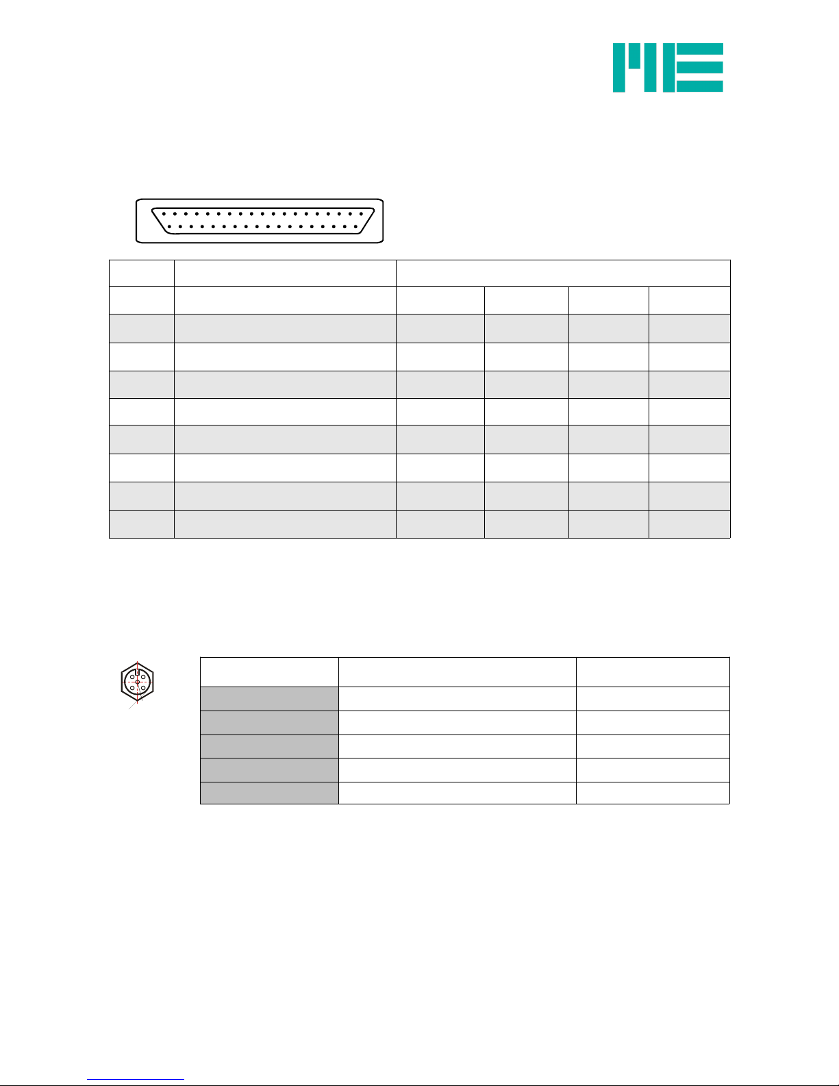
Connection assignment
Connection plan for 37-pin D-sub port
GSV-4USB assignment 37-pin D-sub port (PIN No.)
Channel 1 Channel 2 Channel 3 Channel 4
+U
S
positive sensor supply 20 2 11 29
+U
D
positive differential input 22 4 13 31
QB1000 quarter bridge extension 1kOhm 23 5 14 32
HB half bridge extension 24 6 15 33
-U
D
negative differential input 25 7 16 34
-U
S
negative sensor supply 27 9 18 36
U
E
analogue input 28 10 19 37
screen 1 1 1 1
Table 2: Analogue inputs
Connection assignment for GSV-4USB M12
5-pin port M12x1, type 763
Top view:
5-pin Description Colour code for cables
2 -US negative bridge supply white
1 +US positive bridge supply brown
3 +UD positive differential input blue
4 -UD negative differential input black
5 AUXin input without cable grey
ME-Meßsysteme GmbH
Neuendorfstr. 18a Tel.: +49 3302 89824 60 Mail: info@me-systeme.de
16761 Hennigsdorf Fax: +49 3302 89824 69 Web: www.me-systeme.de 7
1
19
37 20
1
2
4 3
5
Page 8

Connection of full bridge with SUB-D37 version
The following graphics show the connection of a full bridge to channel 1 through to channel
4.
ME-Meßsysteme GmbH
Neuendorfstr. 18a Tel.: +49 3302 89824 60 Mail: info@me-systeme.de
8 16761 Hennigsdorf Fax: +49 3302 89824 69 Web: www.me-systeme.de
Page 9
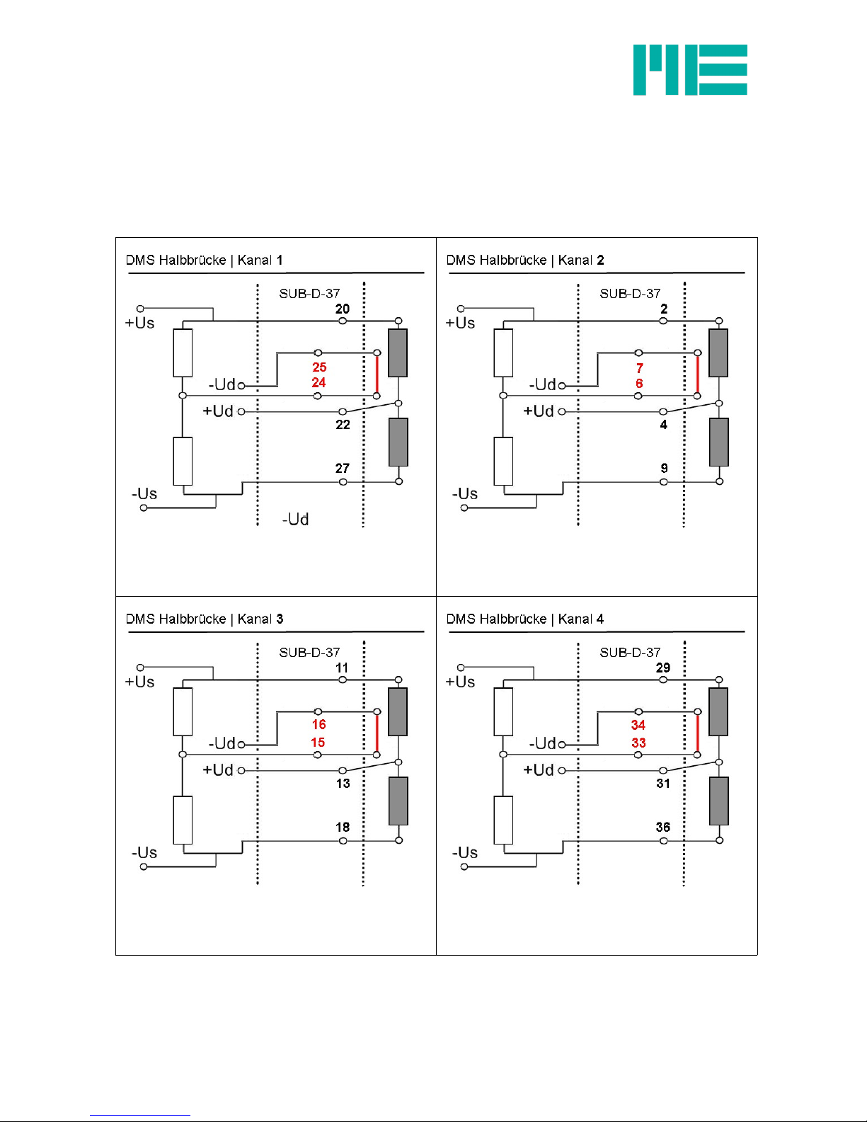
Connection of half bridge with SUB-D37 version
The following graphics show the connection of a half bridge to channel 1 through to channel
4.
The bridge extension should be adapted depending on the application.
ME-Meßsysteme GmbH
Neuendorfstr. 18a Tel.: +49 3302 89824 60 Mail: info@me-systeme.de
16761 Hennigsdorf Fax: +49 3302 89824 69 Web: www.me-systeme.de 9
Page 10
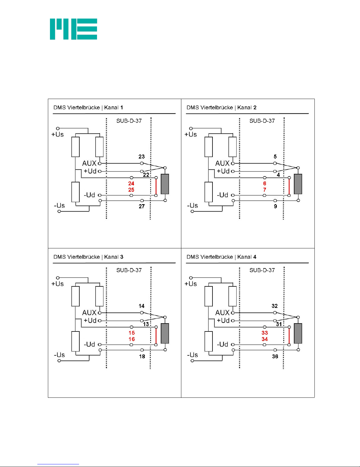
Connection of quarter bridge with SUB-D37 version
The following graphics show the connection of a quarter bridge to channel 1 through to
channel 4.
The bridge extension should be adapted depending on the application.
ME-Meßsysteme GmbH
Neuendorfstr. 18a Tel.: +49 3302 89824 60 Mail: info@me-systeme.de
10 16761 Hennigsdorf Fax: +49 3302 89824 69 Web: www.me-systeme.de
Page 11
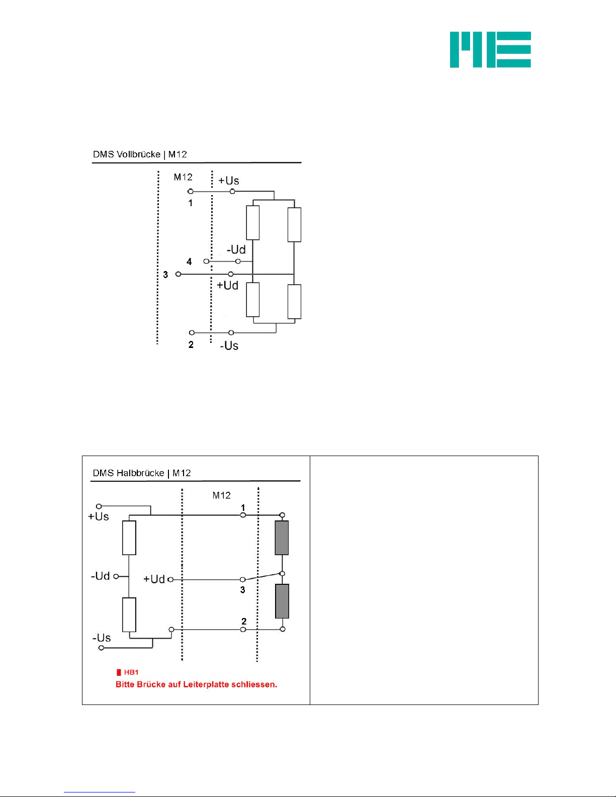
Connection of full bridge with M12 version
The following graphic shows the connection of a full bridge for the M12 version.
Connection of half bridge with M12 version
The following graphic shows the connection of a half bridge for the M12 version.
The bridge extension should be adapted depending on the application.
Please set the solder bridges:
•HB1 when using channel 1
with a half bridge.
•HB2 when using channel 2
with a half bridge.
•HB3 when using channel 3
with a half bridge.
•HB4 when using channel 4
with a half bridge.
Solder bridges: Figure 3: Solder bridges for
configuring bridge extensions
see page 11
ME-Meßsysteme GmbH
Neuendorfstr. 18a Tel.: +49 3302 89824 60 Mail: info@me-systeme.de
16761 Hennigsdorf Fax: +49 3302 89824 69 Web: www.me-systeme.de 11
Page 12
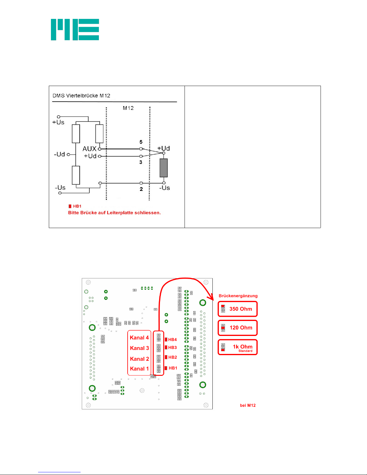
Connection of quarter bridge or PT1000 with M12 version
The following graphic shows the connection of a quarter bridge for the M12 version.
The bridge extension should be adapted depending on the application.
Please set the solder bridges:
•HB1 when using channel 1
with a quarter bridge.
•HB2 when using channel 2
with a quarter bridge.
•HB3 when using channel 3
with a quarter bridge.
•HB4 when using channel 4
with a quarter bridge.
Solder bridges: Figure 3: Solder bridges for
configuring bridge extensions
see page 11
Adapting the bridge extension with M12 version
The bridge extension can be adapted individually for each channel; open the device and
extend the desired solder bridge according to the following figure.
ME-Meßsysteme GmbH
Neuendorfstr. 18a Tel.: +49 3302 89824 60 Mail: info@me-systeme.de
12 16761 Hennigsdorf Fax: +49 3302 89824 69 Web: www.me-systeme.de
Page 13
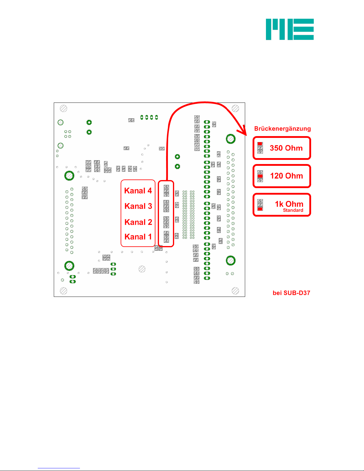
Adapting the bridge extension with Sub-D37 version
The bridge extension can be adapted individually for each channel; open the device and
extend the desired solder bridge according to the following figure.
ME-Meßsysteme GmbH
Neuendorfstr. 18a Tel.: +49 3302 89824 60 Mail: info@me-systeme.de
16761 Hennigsdorf Fax: +49 3302 89824 69 Web: www.me-systeme.de 13
F
Figure 4: Solder bridges for configuring bridge extensions
Page 14
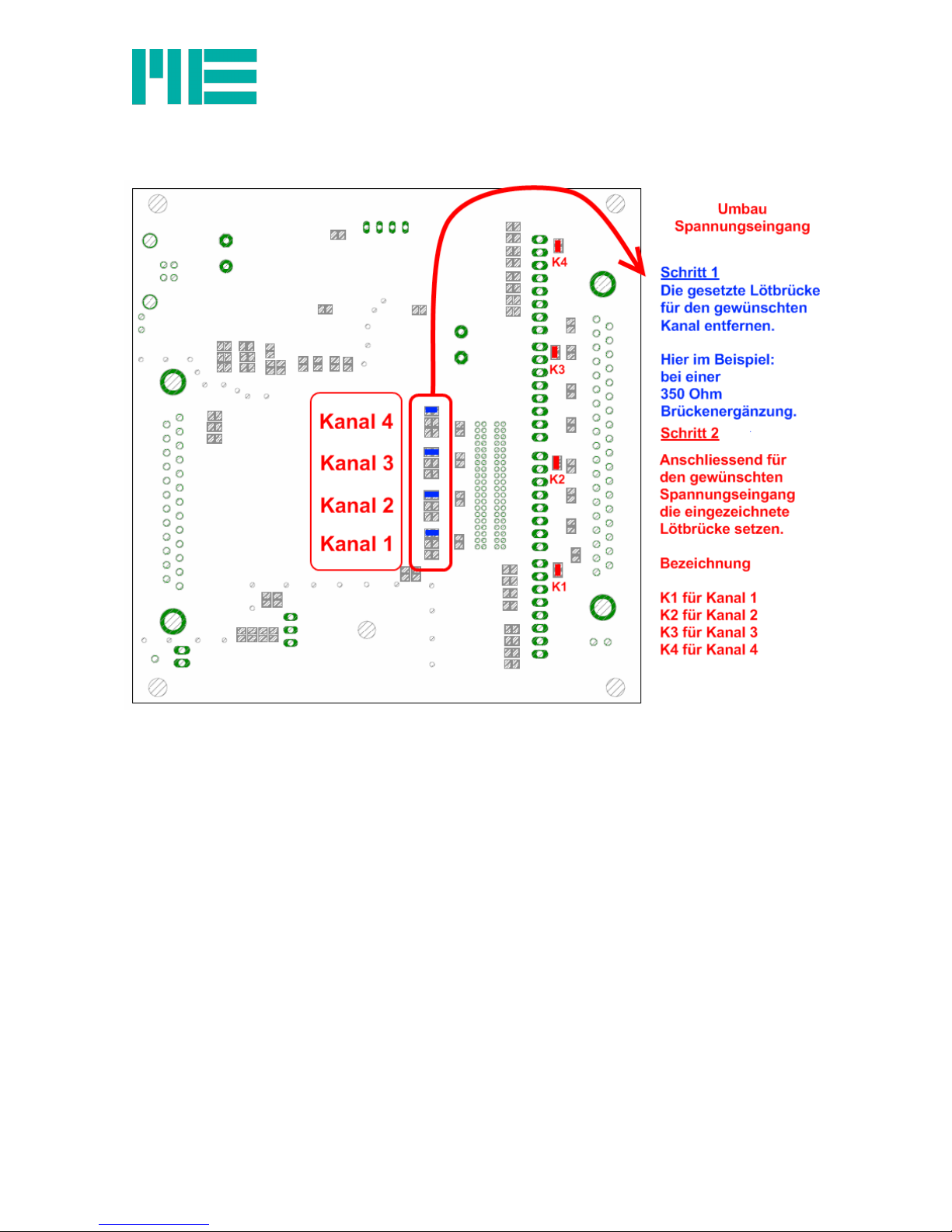
Altering Straingage input to the voltage input
Opening the device
1.Remove both screw covers from the input side and remove the fastening screws from the
front cover.
2.The two hexagonal bolts on the 37-pin D-Sub port must be loosened using a socket
spanner (5 mm).
3.The printed circuit board is pulled out on the side of the 25-pin D-Sub port.
ME-Meßsysteme GmbH
Neuendorfstr. 18a Tel.: +49 3302 89824 60 Mail: info@me-systeme.de
14 16761 Hennigsdorf Fax: +49 3302 89824 69 Web: www.me-systeme.de
Page 15
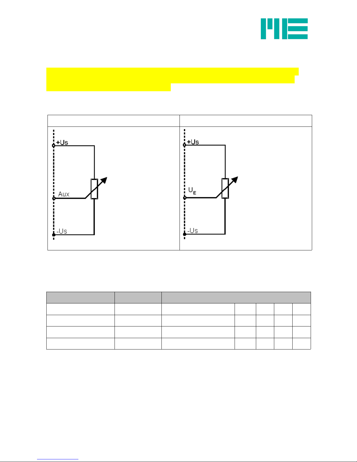
Wiring diagram for position sensors
The measuring amplifier GSV-4USB must be configured by the manufacturer separately
when using it with potentiometric position sensors (linear potentiometers or draw wire
displacement sensors) for the M12 version.
The position sensor’s wiper is connected to the measuring amplifier’s “Aux” input (M12) or
“UE“ (SubD37). The position sensor supplies via the sensor supply +Us and -Us.
5-pin port 37-pin D-SUB port
The potentiometric position sensor is supplied with 2.5 V.
The “Aux” input or UE records voltages of 0...5 V.
Connection assignment
Label 5-pin port 37-pin D-SUB port
CH 1 CH 2 CH 3 CH 4
positive supply +Us 1 positive supply +Us 20 2 11 29
negative supply -Us 2 negative supply -Us 27 9 18 36
“Aux” input 5 UE input 28 10 19 37
ME-Meßsysteme GmbH
Neuendorfstr. 18a Tel.: +49 3302 89824 60 Mail: info@me-systeme.de
16761 Hennigsdorf Fax: +49 3302 89824 69 Web: www.me-systeme.de 15
Page 16
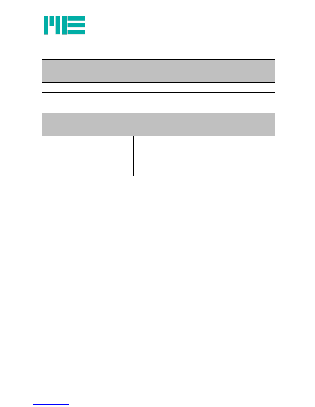
Connection of the Way Con – draw wire sensor SX
4-pin port
Waycon draw wire sensor
SX
5-pin port Label Colour code
M12 sensor-actuator
cable
1 (+supply) 1 positive supply +Us brown
3 (GND) 2 negative supply -Us blue
2 (wiper) 5 “Aux” input white
4-pin port
Waycon draw wire sensor
SX
37-pin D-SUB port
CH 1 CH 2 CH 3 CH 4
1 (+supply) 20 2 11 29 pos. supply +Us
3 (GND) 27 9 18 36 neg. upply -Us
2 (wiper) 28 10 19 37 UE input
ME-Meßsysteme GmbH
Neuendorfstr. 18a Tel.: +49 3302 89824 60 Mail: info@me-systeme.de
16 16761 Hennigsdorf Fax: +49 3302 89824 69 Web: www.me-systeme.de
Page 17

Connection assignment SUB-D25 port
GSV-4USB assignment 25-pin D-sub port (PIN-No.)
IO 5 V fixed voltage output 1
IO GND 2
IO 1 3
IO 2 4
IO 3 5
IO 4 6
IO 5 7
IO 6 8
IO 7 9
IO 8 10
TX 11
RX 12
GND 13
Channel 1 Channel 2 Channel 3 Channel 4
GND 14 17 20 23
0...5V Input 15 18 21 24
AUX Input 16 19 22 25
ME-Meßsysteme GmbH
Neuendorfstr. 18a Tel.: +49 3302 89824 60 Mail: info@me-systeme.de
16761 Hennigsdorf Fax: +49 3302 89824 69 Web: www.me-systeme.de 17
Page 18

Strain Gage measuring amplifier GSV-4BT
Figer 5: GSv-4BT M12
Description
The measuring amplifier GSV-4BT is suited to wireless measurement data acquisition with
wire strain gauge sensors. The GSV-4BT is suitable for connecting Straingage full bridges
and half bridges. For quarter bridges (120 Ohm, 350 Ohm, and 1000 Ohm), there is a
connection option in three-wire technology.
Data is transmitted by radio via the Bluetooth Standard 2.0+EDR with serial port profile
(SPP). The range is 20 m in buildings or up to 100 m when in direct line of sight. Commercial
Bluetooth dongles with Widcom or Toshiba drivers which support the “serial-port-protocol”
are suitable as receivers.
Data rates are possible from 0 Hz to 500 Hz. They are supplied via e.g. a lithium-polymer
battery. By opening the interface for the application software, the module is switched on.
Current consumption is less than 150 mA. When not in use, current consumption is under
10 mA.
A battery can be charged at 5V supply voltage via an integrated charge regulator. Threshold
values or digital outputs can be programmed with the 8 digital outputs
.
Standard PIN: 0000
ME-Meßsysteme GmbH
Neuendorfstr. 18a Tel.: +49 3302 89824 60 Mail: info@me-systeme.de
18 16761 Hennigsdorf Fax: +49 3302 89824 69 Web: www.me-systeme.de
• Bluetooth interface
• 4-channels
• Inputs for Straingage / 0–10 V / PT1000
• Measurement ranges 2 mV/V / 10 mV/V
• Straingage quarter / half / full bridges
• 8 digital inputs / outputs
• Data rate 0 Hz–500 Hz
Page 19

Dimensions
GSV-4BT SD
GSV-4BT LD
ME-Meßsysteme GmbH
Neuendorfstr. 18a Tel.: +49 3302 89824 60 Mail: info@me-systeme.de
16761 Hennigsdorf Fax: +49 3302 89824 69 Web: www.me-systeme.de 19
Page 20

Technical data
Accuracy class 0.05 %
Inputs
Resolution 16 Bit
Straingage inputs
Full bridge
Half bridge
Quarter bridge
89-5000
89-5000
120, 350, 1000
Ohm
Ohm
Ohm
Common mode rejection
at 60 Hz common-mode signal
95–110 dB
Measurement frequencies
Data frequency 0–500 Hz
Sampling frequency 1.92 MHz
Cut-off frequency
analogue
digital
450
Notch filter, configurable
Hz
Outputs
Bridge supply voltage
Current load capacity
2.5
30
Volt
mA
Switching outputs/inputs I/O 1-8
Level
Current load capacity:
TTL level
5 (active High)
5
V
mA
Interface Bluetooth Standard 2.0+EDR
Supply voltage
Nominal range
Current consumption @ 4.2 V DC
Charge regulator
Current consumption @ 5.2 V DC
3.3...4.2
< 150
5.0 ± 0.5
< 450
V DC
mA
V DC
mA
Temperature range
Nominal temperature range
Storage temperature range
Zero point drift
Sensitivity drift
-10…+65
-40…+85
< 0.05
< 0.01
-10…+65
-40…+85
%/10°C
%/10°C
Dimensions
L x W x H 60 x 33 x 10 mm x mm x mm
Protection type
IP64
Table 3: Technical data GSV-4BT
ME-Meßsysteme GmbH
Neuendorfstr. 18a Tel.: +49 3302 89824 60 Mail: info@me-systeme.de
20 16761 Hennigsdorf Fax: +49 3302 89824 69 Web: www.me-systeme.de
Page 21

Wiring diagram
Straingage full bridge
ch 1 ch 2 ch 3 ch 4
+Us 2 13 24 35
+Ud 3 14 25 36
-Ud 4 15 26 37
-Us 5 16 27 38
Sw. 1 12 23 34
ME-Meßsysteme GmbH
Neuendorfstr. 18a Tel.: +49 3302 89824 60 Mail: info@me-systeme.de
16761 Hennigsdorf Fax: +49 3302 89824 69 Web: www.me-systeme.de 21
+Us
-Us
-Ud
+Ud
R1R2R3
R4
Page 22

Straingage half bridge
ch 1 ch 2 ch 3 ch 4
+Us 2
13 24
35
+Ud 3
14 25
36
-Us 5
16 27
38
HBx 8
19 30
41
Sw. 1 12 23 34
The active Straingage R3 and R4 are connected to the terminals +Us,
+Ud and -Us.
HBx: The solder bridges “8”, “19”, “30” or “41” must be closed so that the
internal extension resistors R1 and R2 are activated.
Straingage quarter bridge
ch 1 ch 2 ch 3 ch 4
+Ud 3
14 25
36
-Us 5
16 27
38
HBx 8
19 30
41
AUX 6
17 28
39
QB 120 11
22 33
44
QB 350 10
21 32
43
QB 1000 9
20 31
42
Sw. 1 12 23 34
The active Straingage R4 is connected to the terminals +Ud, AUX and
-Us in 3-wire technology.
HBx: The solder bridges “8”, “19”, “30” or “41” must be closed so that the
internal extension resistors R1 and R2 are activated.
A solder bridge should be set depending on the Straingage resistance
(120/350/1000 Ohm), e.g. 120 Ohm at channel 1: Solder bridge 11
(vertical); 350 Ohm at channel 2: Solder bridge 21 (horizontal).
ME-Meßsysteme GmbH
Neuendorfstr. 18a Tel.: +49 3302 89824 60 Mail: info@me-systeme.de
22 16761 Hennigsdorf Fax: +49 3302 89824 69 Web: www.me-systeme.de
+Us
-Us
-Ud
+Ud
R1
R2
R3
R4
+Us
-Us
-Ud
+Ud
R1
R2
R5
R4
AUX
Page 23

PT-1000
ch 1 ch 2 ch 3 ch 4
AUX 6
17 28
39
7
18 29
40
-Us 5
16 27
38
QB 1000 9
20 31
42
HBx 8
19 30
41
Sw. 1 12 23 34
HBx: The solder bridges “8”, “19”, “30” or “41” must be closed so that the
internal extension resistors R1 and R2 are activated.
The solder bridges “9”, “20”, “31” or “42” (horizontal) must be closed.
Thermocouple cable type K
ch 1 ch 2 ch 3 ch 4
+Ud 3 14 25 36
-Ud 4 15 26 37
-Us 5
- -
-
QB 1000 9
- -
-
7
- -
-
HBx 8
19 30
41
Sw. 1 12 23 34
AUX 6
17 28
39
A reference sensor PT1000 must be connected to channel 1, Ue “0-5 V”
terminal, AUX and -Us.
The thermocouple cable is connected to terminals +Ud and -Ud.
ME-Meßsysteme GmbH
Neuendorfstr. 18a Tel.: +49 3302 89824 60 Mail: info@me-systeme.de
16761 Hennigsdorf Fax: +49 3302 89824 69 Web: www.me-systeme.de 23
-Us
0-5V
PT
1000
AUX
-Ud
+Ud
- (weiß)
+ (grün)
+Us
-Us
-Ud
0-5V
R1
R2
R5
PT
1000
AUX
Page 24

Voltage input 0-5 V
ch 1 ch 2 ch 3 ch 4
Ue „0-5V“ 7
18 29
40
-Us 5
16 27
38
Sw. 1 12 23 34
Voltage input 0-10 V
ch 1 ch 2 ch 3 ch 4
Ue „0-5V“ 7
18 29
40
-Us 5
16 27
38
Sw. 1 12 23 34
ME-Meßsysteme GmbH
Neuendorfstr. 18a Tel.: +49 3302 89824 60 Mail: info@me-systeme.de
24 16761 Hennigsdorf Fax: +49 3302 89824 69 Web: www.me-systeme.de
-Us
0-5V
0-5V
-Us
0-5V
0-5V
Page 25

Technical data GSV-4BT M12
Accuracy class 0.05 %
Inputs
Resolution 16 Bit
Straingage inputs
Full bridge
Half bridge
Quarter bridge
89-5000
89-5000
120, 350, 1000
Ohm
Ohm
Ohm
Common mode rejection
at 60 Hz common-mode signal
95–110 dB
Measurement frequencies
Data frequency 0–500 Hz
Sampling frequency 1.92 MHz
Cut-off frequency
analogue
digital
450
Notch filter, configurable
Hz
Outputs
Bridge supply voltage
Current load capacity
2.5
30
Volt
mA
Switching outputs/inputs I/O 1-8
Level
Current load capacity:
TTL level
5 (active High)
5
V
mA
Interface Bluetooth Standard 2.0+EDR
Supply voltage
Nominal range
Current consumption @ 4.2 V DC
Charge regulator
Current consumption @ 5.2 V DC
3.3...4.2
< 150
9,0 ... 36,0
< 100
V DC
mA
V DC
mA
Temperature range
Nominal temperature range
Storage temperature range
Zero point drift
Sensitivity drift
-10…+65
-40…+85
< 0.05
< 0.01
-10…+65
-40…+85
%/10°C
%/10°C
Dimensions
L x B x H for GSV-4BT M12 120 x 80 x 55 mm x mm x mm
Protection type
for GSV-4BT M12
IP65
ME-Meßsysteme GmbH
Neuendorfstr. 18a Tel.: +49 3302 89824 60 Mail: info@me-systeme.de
16761 Hennigsdorf Fax: +49 3302 89824 69 Web: www.me-systeme.de 25
Page 26
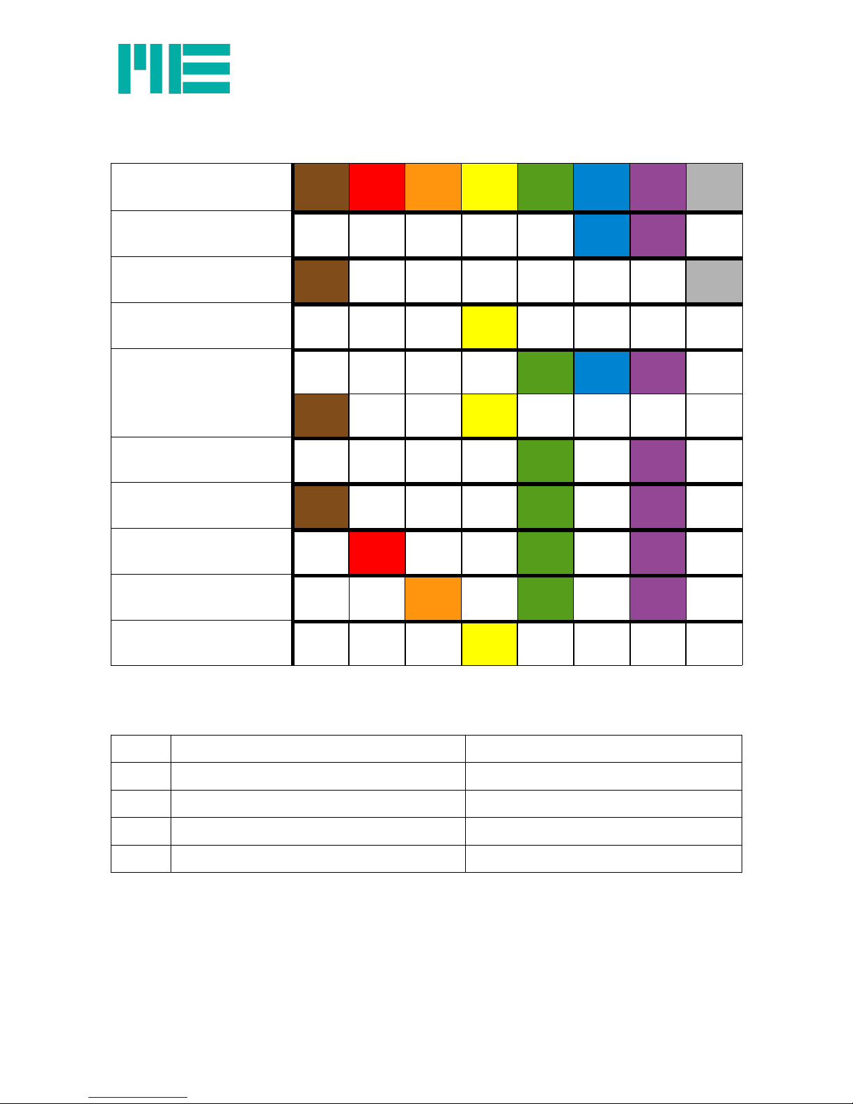
Switch configuration GSV-4BT M12
Input
1
brown2red3 orange4yellow5green6blue7purple8grey
Straingage OFF OFF OFF OFF OFF ON ON OFF
PT1000 ON OFF OFF OFF OFF OFF OFF ON
Voltage OFF OFF OFF ON OFF OFF OFF OFF
Thermo cabel
+
on channel 1 - PT1000
OFF OFF OFF OFF ON ON ON OFF
ON OFF OFF ON OFF OFF OFF OFF
Half bridge OFF OFF OFF OFF ON OFF ON OFF
Quarter bridge 1000 Ohm ON OFF OFF OFF ON OFF ON OFF
Quarter bridge 120 Ohm OFF ON OFF OFF ON OFF ON OFF
Quarter bridge 350 Ohm OFF OFF ON OFF ON OFF ON OFF
Displacement sensor OFF OFF OFF ON OFF OFF OFF OFF
Pin configuration for external supply voltage M8, 4-pole
The external supply voltage can be connected via 4-pole round plug connector M8.
Pin Function Sensor-Aktor Cabel M8
1 Supply voltage 9...28 V DC brown
2 Battery 4,2V white
3 GND Supply voltage blue
4 Battery GND black
ME-Meßsysteme GmbH
Neuendorfstr. 18a Tel.: +49 3302 89824 60 Mail: info@me-systeme.de
26 16761 Hennigsdorf Fax: +49 3302 89824 69 Web: www.me-systeme.de
Page 27

Pin configuration GSV-4BT M12
Port side
5-pol. Description Colour
2 -US negative bridge supply white
1 +US positive bridge supply brown
3 +UD positive differential input blue
4 -UD negative differential input black
5 AUX in input without cable grey
Connection plan for GSV-4BT M12
Half bridge Quarter bridge
Voltage input Potentiometric input
ME-Meßsysteme GmbH
Neuendorfstr. 18a Tel.: +49 3302 89824 60 Mail: info@me-systeme.de
16761 Hennigsdorf Fax: +49 3302 89824 69 Web: www.me-systeme.de 27
1
2
4 3
5
+Us
-Us
-Ud
+Ud
R1
R2
R5
R4
AUX
+Us
-Us
-Ud
+Ud
R1
R2
R3
R4
Page 28

PT1000 Thermocabel type K
Measurement resolution
The achievable relation signal / noise depends on the ambient conditions (cable length, shield) and
on the setted data rate. The graphic illustrates the resolution with 1m cable, measuring range
±2mV/V and 350 Ohm Straingage – Simulator on channel 1.
ME-Meßsysteme GmbH
Neuendorfstr. 18a Tel.: +49 3302 89824 60 Mail: info@me-systeme.de
28 16761 Hennigsdorf Fax: +49 3302 89824 69 Web: www.me-systeme.de
Page 29

Order variants GSV-4BT
Type Description
GSV-4BT Miniature variant, external battery
Li-Ion 1S/1P/2.6Ah Li-Ionen battery, 2,6Ah, for GSV-4BT
Adapter-GSV-4BT Connecting Adapter with solder connection for GSV-4BT
Adapter-GSV-4BT MSTB Connecting Adapter with screw terminals RM2,5 for GSV-4BT
Bluetooth-USB-Adapter Bluetooth reciever with USB Port (to 100m)
GSV-4BT M12 Variant with housing and plug connector, integrated battery,„Long-
Distance“ in connection with Bluetooth USB-Dongle UD100
GSV-4BT LD Miniature Variant, external battery, „Long Distance“ to 300m in
connection with Bluetooth USB-Dongle UD100
Bluetooth USB-Dongle UD100 Bluetooth reciever with USB Port (to 300m, in connection with GSV-
4BT M12 or GSV-4BT LD
ME-Meßsysteme GmbH
Neuendorfstr. 18a Tel.: +49 3302 89824 60 Mail: info@me-systeme.de
16761 Hennigsdorf Fax: +49 3302 89824 69 Web: www.me-systeme.de 29
Page 30
Programming / configuration
For programming Windows DLL and Labview Vis can be downloaded from the website.
Optionally it is possible to programm the measuring amplifier directly via serial interface or
USB with ASCII Codes.
Scaling of measured values
Each channel can be configured individually for a defined measuring range, e.g.
for measuring
•with wire strain gauges 2 mV/V,
•with wire strain gauges 10 mV/V,
•with active sensors 0-5 V,
•with temperature sensors PT1000,
•with type K thermocouples,
•with active sensors 0–10 V,
The measuring range is set using the command “set_gain”.
105% of the input signal matches a value range of 0x0000 to 0xFFFF.
Measuring range 2.0 mV/V
Measuring range ±2 mV/V (set_gain 0xB2 <p1> <p2>) with p1=ch, p2=0x01
Input signal in mV/V Measuring range in % 16 Bit output value (hexadecimal)
2.1 105.00% FFFFh
2.0 100.00% F9E7h
0.0 0.00% 8000h
-2.0 -100.00% 0618h
-2.1 -105.00% 0000h
Conversion of digital output value to analogue input signal:
Output value = Highbyte * 256 + Lowbyte;
Input signal Ud = (output value - 32768) / 32768 * 2.10 mV/V;
Measuring range 10.0 mV/V
Measuring range ±10 mV/V (set_gain 0xB2 <p1> <p2>) with p1=ch, p2=0x02
Input signal in mV/V Measuring range in % 16 Bit output value (hexadecimal)
10.5 105.00% FFFFh
10.0 100.00% F9E7h
0.0 0.00% 8000h
-10.0 -100.00% 0618h
ME-Meßsysteme GmbH
Neuendorfstr. 18a Tel.: +49 3302 89824 60 Mail: info@me-systeme.de
30 16761 Hennigsdorf Fax: +49 3302 89824 69 Web: www.me-systeme.de
Page 31

Measuring range ±10 mV/V (set_gain 0xB2 <p1> <p2>) with p1=ch, p2=0x02
-10.5 -105.00% 0000h
Conversion of digital output value to analogue input signal:
Output value = Highbyte * 256 + Lowbyte;
Input signal Ud = (output value - 32768) / 32768 * 10.5 mV/V;
Measuring range 0.0 to 5 V
Measuring range 0-5 V (set_gain 0xB2 <p1> <p2>) with p1=ch, p2=0x03
Input signal in V Measuring range in % 16 Bit output value (hexadecimal)
5.25 105.00% FFFFh
5.0 100.00% F9E7h
0.0 0.00% 8000h
Conversion of digital output value to analogue input signal:
Output value = Highbyte * 256 + Lowbyte;
Input signal Ud = (output value - 32768) / 32768 * 5.25 V;
Measuring range 0.0 to 10 V
Measuring range 0-10 V (set_gain 0xB2 <p1> <p2>) with p1=ch, p2=0x07
Input signal in V Measuring range in % 16 Bit output value (hexadecimal)
10.5 105.00% FFFFh
10 100.00% F9E7h
0.0 0.00% 8000h
Conversion of digital output value to analogue input signal:
Output value = Highbyte * 256 + Lowbyte;
Input signal Ue = (output value - 32768) / 32768 * 10.5 V;
Measuring range PT1000
Measuring range PT1000 (set_gain 0xB2 <p1> <p2>) with p1=ch, p2=0x04
Input signal in °C Measuring range in % 16 Bit output value (hexadecimal)
1050 105% FFFFh
1000 100% F9E7h
0.0 0.0% 8000h
-40 -4% 6DB0h
Conversion of digital output value to analogue input signal:
Output value = Highbyte * 256 + Lowbyte;
Input signal Ue = (output value - 32768) / 32768 * 1050 °C;
ME-Meßsysteme GmbH
Neuendorfstr. 18a Tel.: +49 3302 89824 60 Mail: info@me-systeme.de
16761 Hennigsdorf Fax: +49 3302 89824 69 Web: www.me-systeme.de 31
Page 32

Measuring range K thermocouple cable
Measuring range K-thermocouple cable (set_gain 0xB2 <p1> <p2>) with p1=ch, p2=0x06
Input signal in °C Measuring range in % 16 Bit output value (hexadecimal)
1050 105% FFFFh
1000 100% F9E7h
0.0 0.0% 8000h
-40 -4% 6DB0h
Conversion of digital output value to analogue input signal:
Output value = Highbyte * 256 + Lowbyte;
Input signal Ud = (output value - 32768) / 32768 * 1050 °C;
Commands for configuration
The code of the command concerned is sent to the measuring amplifier for configuration.
Some commands expect parameters, e.g. the channel number “ch” and potentially other
bytes.
Note: To set the configuration, the data transfer should be interrupted by sending the
command “stop_transmission”.
After completing the configuration, the data transfer can be restarted again by executing the
command “start_transmission”.
Notes: After each switch-on, the “normal mode” must be set in order to send commands
(0x26 01 62 65 72 6C 69 6E).
List of commands
The table lists the available commands (rev0x0B) and their hexadecimal codes.
Commands Code p1 p2 p3 p4 p5 p6 p7 p8 p9
set_zero 0C ch
save_konfiguration 09 B
restore_konfiguration 0A B
set_offset 0B ch B HB B LB
get_offset 0D ch B
set_frequency 12 B
get_frequency 16
get_serial_number 1F
set_serial_number 1E B B B B B B B B
set_threshold 20 B HB LB
ME-Meßsysteme GmbH
Neuendorfstr. 18a Tel.: +49 3302 89824 60 Mail: info@me-systeme.de
32 16761 Hennigsdorf Fax: +49 3302 89824 69 Web: www.me-systeme.de
Page 33

Commands Code p1 p2 p3 p4 p5 p6 p7 p8 p9
get_threshold 21 B
stop_transmision 23
start_transmision 24
set_mode 26 B B B B B B B
get_mode 27
set_tx_status 28 B
get_tx_status 29
get_firmware_version 2B
set_power_on 2C B
get_power_on 2D
set_threshold_mode 2E ch B
get_threshold_mode 2F
get_value 3B
set_cal_factor 88 ch B HB B LB
get_cal_factor 89 ch B
set_rs232 B0 B
get_rs232 B1
set_gain B2 ch B
get_gain B3
set_unit B4 ch B
get_unit B5 ch
set_digital B6 B B
get_digital B7 B
set_digital_on_off B8 B B
get_digital_port B9
set_user_scale BA ch HB B B LB
get_user_scale BB ch HB B B LB
set_user_sring BC HB B B B LB
get_user_sring BD
reserviert BE
ME-Meßsysteme GmbH
Neuendorfstr. 18a Tel.: +49 3302 89824 60 Mail: info@me-systeme.de
16761 Hennigsdorf Fax: +49 3302 89824 69 Web: www.me-systeme.de 33
Page 34

Commands Code p1 p2 p3 p4 p5 p6 p7 p8 p9
get_digital_port A BF
set_can_bitrate C0 B
get_can_bitrate C1
reserviert C2
reserviert C3
set_can_id C5 B HB B B LB
get_can_id C6 B
reserviert C7 ch
reserviert C8 ch
reserviert D0 B B B B B B B
reserviert D1 ch
reserviert D2 B B
reserviert D3
reserviert D4
reserviert D5 B B
reserviert D6
Table 4: Command list for GSV-4 (ch = channel number), B = byte, HB = high byte, LB = low byte)
Commands in grey are reserved for the initial setup or calibration. The commands shaded
grey are only available after restarting.
Description of commands
set_gain (B2)
With the command set_gain, the 4 inputs on the measuring amplifier can be configured
individually for various sensor types.
Parameters in HEX Description
01 Straingage input ±2 mV/V
02 Straingage input ±10 mV/V
03 Analogue input 0-5 V
04 Input for PT1000 -40°C ... 1000 °C
06 Input for K-thermocouple cable -40°C ... 1000 °C
07 Analogue input 0 – 10 V
ME-Meßsysteme GmbH
Neuendorfstr. 18a Tel.: +49 3302 89824 60 Mail: info@me-systeme.de
34 16761 Hennigsdorf Fax: +49 3302 89824 69 Web: www.me-systeme.de
Page 35

set_frequency (12)
The data frequency is set with the command set_frequency. The measurement data is
acquired with the data frequency and are ready to be transmitted via the interface (CANBus,
RS232, Bluetooth, GPRS, etc.) By setting the data frequency, the digital filter is set
automatically, see data frequencies and filter properties.
After executing the command “start_transmission”, the measurement data is transmitted
steadily at the set data frequency. After executing the command “stop_transmission”, the
measuring data is only sent when required. It can be requested with the command
“get_value” or for devices with CAN bus via CAN-Sync_ID (page 45).
Note: Care should be taken to ensure that the request for measured values does not occur
more frequently than the set data frequency. Otherwise, a current measured value will not
be available every time there is a request. The same measured values are requested
repeatedly.
Parameters in HEX Data frequency in Hz( nominal) Data frequency in Hz( effective)
A0 0,63 0,625
A1 1,25 1,250
A2 2,5 2,500
A3 3,75 3,750
A4 6,25 6,250
A5 7,5 7,500
A6 12,5 12,400
A7 15 14,7
A8 25 24,4
A9 125 125
AA 250 250
AB 500 500
AC 937,5 ...
ME-Meßsysteme GmbH
Neuendorfstr. 18a Tel.: +49 3302 89824 60 Mail: info@me-systeme.de
16761 Hennigsdorf Fax: +49 3302 89824 69 Web: www.me-systeme.de 35
Page 36

set_can_bitrate (C0) / get_can_bitrate (C1)
Parameters in HEX Bitrate in kbit/s
10 20
20 50
30 80
40 100
50 125
60 250
70 500 (standard)
80 1000
save_configuration (0A) / restore_configuration (09)
The entire configuration (data frequency, configuration of inputs, etc.) can be saved and
restored as a parameter set. Two memories are available for the configuration.
Parameters in HEX Description
01 Manufacturer setting
02 User setting 1
03 User setting 2
set_user_scale (BA) / get_user_scale (BB)
A scaling factor in 32 Bit format can be stored for each channel.
This scaling factor is stored in the EEProm of the measuring amplifier and can be read with
get_user_scale.
Parameters in HEX Memory No. Label
01 1 Channel 1
ME-Meßsysteme GmbH
Neuendorfstr. 18a Tel.: +49 3302 89824 60 Mail: info@me-systeme.de
36 16761 Hennigsdorf Fax: +49 3302 89824 69 Web: www.me-systeme.de
Page 37
Parameters in HEX Memory No. Label
02 2 Channel 2
03 3 Channel 3
04 4 Channel 4
Number format:
Sign Index Significand
Bit 0 Bit 1 ... Bit 8 Bit 9 ... Bit 31
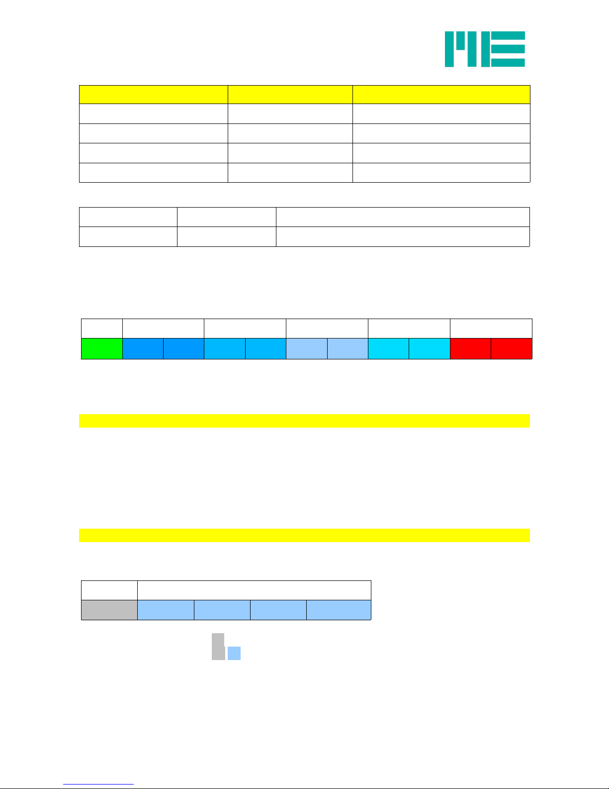
Protocol for measured values
Measured values are framed by a prefix 0xA5 and a postfix from the sign 0x0D 0x0A
(carriage return linefeed).
The entire frame is 11 bytes long.
Prefix Channel 1 Channel 2 Channel 3 Channel 4 Postfix
A5 HB LB HB LB HB LB HB LB 0D 0A
Table 5: Protocol for transmitting the measured values via RS232 interface
Protocol for commands
After switching on, only the commands:
get_value (0x3B)
set_mode (0x26 01 62 65 72 6C 69 6E)
get_mode (0x27)
get_tx_status (0x29)
get_firmware_version (0x2B)
can be used! To be able to use all of the commands, “set_mode” has to be sent.
Commands begin with the code followed by parameters.
Code Parameter
xx p1 p2 ... pn
Examples:
Requesting serial number 1F
Setting channel 1 to zero: 0C 01
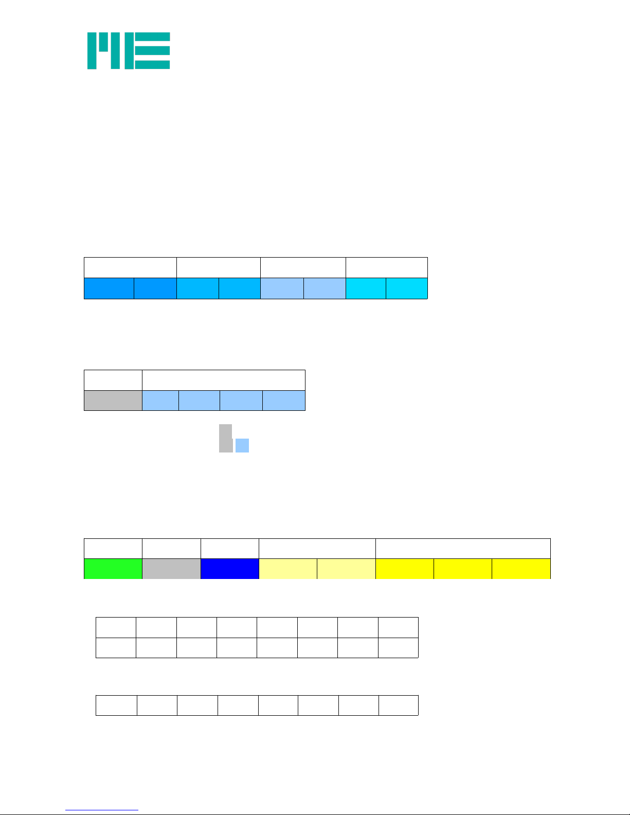
Protocol for responding to commands
Responses are framed by a prefix 0x3B and a postfix from the sign 0x0D 0x0A (carriage
ME-Meßsysteme GmbH
Neuendorfstr. 18a Tel.: +49 3302 89824 60 Mail: info@me-systeme.de
16761 Hennigsdorf Fax: +49 3302 89824 69 Web: www.me-systeme.de 37
Page 38

return linefeed).
The entire frame has a variable length. The number of frames still to follow is given with “n”.
The number of variable bytes is defined in the fourth and fifth Byte with the data word “len”.
The entire length of the response is (10 + len) bytes.
The command “get_value” is an exception. The response to this command takes place with
a protocol for measured values.
Prefix Code n len No. len bytes Postfix
3B xx B HB LB aa bb cc p1 p2 ... pn 0D 0A
Table 6: Protocol for responding to commands
Example: Releasing commands
Send: 0x26 01 62 65 72 6C 69 6E
Example: Locking commands
Send: 0x26 00 62 65 72 6C 69 6E
Example: Request serial number
Send: 0x23
Send: 0x1F
Receive 0x 3B 1F 0100 08 30 35 30 30 38 34 34 39 30 35 30 0D 0A
Send 0x24
Result: The serial number is “08449050”.
Example: Change status(Send measured value OFF/ON)
To permanently save the value send stop or start measured value, the command
set_tx_status (0x28<p1>) can be used.
Parameters in HEX Parameters in Bit Current After switching on
00 0 0 0 0 0 0 0 0 Send measured value OFF Send measured value OFF
01 0 0 0 0 0 0 0 1 Send measured value OFF Send measured value ON
02 0 0 0 0 0 0 1 0 Send measured value ON Send measured value OFF
03 0 0 0 0 0 0 1 1 Send measured value ON Send measured value ON
Send: 0x23
Send: 0x29
Receive : 0x 3B 29 0100 01 30 33 33 01 0D 0A
Result: Current-OFF , After switching on-ON
ME-Meßsysteme GmbH
Neuendorfstr. 18a Tel.: +49 3302 89824 60 Mail: info@me-systeme.de
38 16761 Hennigsdorf Fax: +49 3302 89824 69 Web: www.me-systeme.de
Page 39

Send: 0x28 02
Send: 0x29
Receive : 0x 3B 29 0100 01 30 33 33 02 0D 0A
Result: Current-ON , After switching on-OFF
Digital IOs
The entire port is always read (IO8 to IO1).
GSV-4CAN assignment:
Digital IO GSV-4CAN GSV-4BT Port
01 Digital 1 IO1 IO1
02 - IO2 IO2
03 Digital 2 IO3 IO3
04 IO4 IO4
05 Digital 3 IO5 IO5
06 IO6 IO6
07 Digital 4 IO7 IO7
08 Digital 5 IO8 IO8
Example: Read port
Send: 0x23
Send: 0xB9
Receive : 0x 3B B9 0100 01 30 33 33 00 0D 0A
Result: all inputs and outputs are “low”
Parameters in HEX Parameters in Bit Port
00 0 0 0 0 0 0 0 0 IO8 IO7 IO6 IO5 IO4 IO3 IO2 IO1
The digital port can be configured with set_digital (0xB6 <p1><p2>) and
set_digital_on_off(0xB8 <p1> <p2>). The port is set with <p1>/
set_digital (0xB6 <p1> <p2>)
Parameters in HEX <p2> Description
00 Eingang
01 Ausgang
02 get_Value
ME-Meßsysteme GmbH
Neuendorfstr. 18a Tel.: +49 3302 89824 60 Mail: info@me-systeme.de
16761 Hennigsdorf Fax: +49 3302 89824 69 Web: www.me-systeme.de 39
Page 40

Parameters in HEX <p2> Description
0A Tara all
0B Tara Kanal1
0C Tara Kanal2
0D Tara Kanal3
0E Tara Kanal4
0F Slave
10 Master
11 SW1
12 SW2
13 SW3
14 SW4
15 SW5
16 SW6
17 SW7
18 SW8
21 SW1 rel.
... ...
28 SW8 rel.
31 SW1 1s
... ...
38 SW8 1s
41 SW1 rel. 1s
... ...
48 SW8 rel. 1s
51 SW1 inv.
ME-Meßsysteme GmbH
Neuendorfstr. 18a Tel.: +49 3302 89824 60 Mail: info@me-systeme.de
40 16761 Hennigsdorf Fax: +49 3302 89824 69 Web: www.me-systeme.de
Page 41

Parameters in HEX <p2> Description
... ...
58 SW8 inv.
61 SW1 inv. rel.
... ...
68 SW8 inv. rel.
71 SW1 inv. 1s
... ...
78 SW8 inv. 1s
81 SW1 inv. rel. 1s
... ...
88 SW8 inv. rel. 1s
set_digital_on_off(0xB8 <p1> <p2>)
Parameters in
HEX <p2>
Parameters in Bit Port Description
00 0 0 0 0 0 0 0 0 For IO1 to IO8 OFF
01 0 0 0 0 0 0 0 1 For IO1 to IO8 ON
Example: Change IO1
Send: 0x23
Send: 0xB6 01 0B
Send: 0xB7
Receive : 0x 3B B7 0100 02 30 33 33 01 0B 0D 0A
Result: IO1 is configured as Tara for channel1
Send: 0xB6 01 00
Send: 0xB7
Receive : 0x 3B B7 0100 02 30 33 33 01 00 0D 0A
Send: 0x24
Result: IO1 is configured as an input and can be read with 0xB9
ME-Meßsysteme GmbH
Neuendorfstr. 18a Tel.: +49 3302 89824 60 Mail: info@me-systeme.de
16761 Hennigsdorf Fax: +49 3302 89824 69 Web: www.me-systeme.de 41
Page 42

set_threshold (0x20 <p1> <p2>)
Parameters in HEX <p1> Description Channel
assignment
Switching threshold
01 SW1 1 ON
02 SW1 1 OFF
03 SW2 1 ON
04 SW2 1 OFF
05 SW3 2 ON
06 SW3 2 OFF
07 SW4 2 ON
08 SW4 2 OFF
09 SW5 3 ON
0A SW5 3 OFF
0B SW6 3 ON
0C SW6 3 OFF
0D SW7 4 ON
0E SW7 4 OFF
0F SW8 4 ON
10 SW8 4 OFF
By setting the on and off switching thresholds differently, a hysteresis can be programmed.
The second parameter (<p2>) is the switching threshold in HEX e.g.: 0x89 FF.
Caution: in order to compare the threshold value with the measured value directly, it has to
be added with 0x80 00.
Example: Configuration of SW1 IO8 ( or digital 5)
Send: 0x 23
Send: 0x B6 08 11
Configure IO8 for SW1
Send: 0x 20 01 01 00
The turn-on threshold of SW1 is set to 0x81 00.
Send: 0x 20 02 FE 00
The turn-off threshold of SW1 is set to 0x7E 00.
ME-Meßsysteme GmbH
Neuendorfstr. 18a Tel.: +49 3302 89824 60 Mail: info@me-systeme.de
42 16761 Hennigsdorf Fax: +49 3302 89824 69 Web: www.me-systeme.de
Page 43

If the measured value increases above 0x81 00, IO8 is switched on. If the measured value
falls below 0x7E 00, IO8 is switched off.
Analogue input
Example: Requesting the configuration of analogue inputs
Send: 0x23
Send: 0xB3
Receive : 0x 3B B3 0100 04 30 35 30 01 01 02 03 0D 0A
Send 0x24
Result: Channel 1 = 2 mV/V, channel 2 = 2 mV/V, channel 3 = 10 mV/V, channel 4 = 0-5 V;
Example: Setting the configuration of analogue inputs
Specification: configuring channel 1 to channel 4 for PT1000
Send: 0x23
Send: 0xB2 01 04
Send: 0xB2 02 04
Send: 0xB2 03 04
Send: 0xB2 04 04
Send 0x24
Example: Setting the data frequency to 12.5 Hz
Specification: The measured value should be sent steadily with a frequency of approx.
12.5/s.
Send: 0x23
Send: 0xA6
Send 0x24
ME-Meßsysteme GmbH
Neuendorfstr. 18a Tel.: +49 3302 89824 60 Mail: info@me-systeme.de
16761 Hennigsdorf Fax: +49 3302 89824 69 Web: www.me-systeme.de 43
Page 44
CAN bus
Devices with CAN bus have the same command structure as devices with serial interfaces
or Bluetooth or GPRS. Prefixes and postfixes are omitted if the measured values and
responses are sent within a CAN bus frame.
Protocol for measured values
Measured values via CAN are always transmitted in a CANbus frame. Bytes 1 to 8 include
the measurement data of the 4 channels with 16 bit each. First the highbyte (HB) and then
the lowbyte (LB) is sent.
Channel 1 Channel 2 Channel 3 Channel 4
HB LB HB LB HB LB HB LB
Table 11: CAN frame with measurement data;
Protocol for commands
Commands begin with the code followed by parameters.
Code Parameter
xx p1 p2 ... pn
Examples:
Requesting serial number 1F
Setting channel 1 to zero: 0C 01
Protocol for responding to commands
Commands for the measuring amplifier are transmitted in the CAN frame (data range). If the
measuring amplifier sends a response, a command response frame is sent.
Head frame:
Prefix Code n len No.
3B xx B HB LB aa bb cc
Table 12: Head frame for responding to commands via CAN bus
Frame 1 ... n
B B B B B B B B
B B B B B B B B
...
...
B B B B B B B B
Table 13: Following frame for responding to commands via CAN bus
ME-Meßsysteme GmbH
Neuendorfstr. 18a Tel.: +49 3302 89824 60 Mail: info@me-systeme.de
44 16761 Hennigsdorf Fax: +49 3302 89824 69 Web: www.me-systeme.de
Page 45

Example: Request serial number
Send: 0x23
Send: 0x1F
Receive 0x 3B 1F 01 00 08 30 35 30
0x 30 38 34 34 39 30 35 30
Send 0x24
Result: The serial number is “08449050”.
Example: Requesting the configuration of analogue inputs
Send: 0x23
Send: 0xB3
Receive 0x 3B B3 01 00 04 30 35 30
0x 01 01 02 03
Send 0x24
Result: Channel 1 = 2 mV/V, channel 2 = 2 mV/V, channel 3 = 10 mV/V, channel 4 = 0-5 V;
Example: Setting the configuration of analogue inputs
Specification: Configuring channel 1 to channel 4 for 0 - 5V
Send: 0x23
Send: 0xB2 01 03
Send: 0xB2 02 03
Send: 0xB2 03 03
Send: 0xB2 04 03
Send 0x24
Configuring the CAN-ID
set_id(0xC5 <p1> <p2>)
CAN-ID for receiving measurement data <p1>=0x01
The default value of CAN-ID for receiving measurement data is 0x00 00 06 10 (<p2>).
CAN-ID for receiving responses <p1>=0x02
The default value of CAN-ID for receiving responses is 0x00 00 06 11 (<p2>).
CAN-ID for sending commands <p1>=0x06
The default value of CAN-ID for sending commands is 0x00 00 01 11 (<p2>).
CAN-ID for synchronising the measurement data <p1>=0x05
To request measured values, the same CAN-ID is available for all measuring amplifiers
(CAN-Sync-ID). All frames with this CAN-Sync-ID trigger the sending of a measured value.
ME-Meßsysteme GmbH
Neuendorfstr. 18a Tel.: +49 3302 89824 60 Mail: info@me-systeme.de
16761 Hennigsdorf Fax: +49 3302 89824 69 Web: www.me-systeme.de 45
Page 46

The default value of CAN-Sync-ID for sending is 0x00 00 01 10 (<p2>).
Note: The CAN-ID is changed immediately (this should be noted particularly for the ID for
sending commands and the CAN baud rate.)
Example: Configuring the CAN-Bitrate
Send: 0x 23
Send: 0x C0 60
Converting the baud rate to 250 kBit on the CAN bus (or CAN adapter)
Send: 0x C1
Receive 0x 3B C1 01 00 01 30 35 30
0x 60
Send 0x 24
Example: Configuring the CAN-ID
Send: 0x 23
Send: 0x C6 06
Receive 0x 3B C6 01 00 05 30 35 30
0x 06 00 00 01 11
The CAN-ID for receiving commands is set to 0x00 00 01 11.
Send: 0x C5 06 00 00 01 00
Converting the ID to 0x00 00 01 00 for sending commands in the program.
Send: 0x C6 06
Receive 0x 3B C6 01 00 05 30 35 30
0x 06 00 00 01 00
Send 0x 24
The CAN-ID for receiving commands is set to 0x00 00 01 00.
Data frequency and filter
Analogue filter
The integrated analogue filter is a first-order low-pass filter with a cut-off frequency of
1 kHz. It is set as an antialiasing filter for the A-D converter. This filter is permanently
installed and cannot be changed.
Digital filter
The digital filter is indirectly set with the data frequency. The effective data frequency may
ME-Meßsysteme GmbH
Neuendorfstr. 18a Tel.: +49 3302 89824 60 Mail: info@me-systeme.de
46 16761 Hennigsdorf Fax: +49 3302 89824 69 Web: www.me-systeme.de
Page 47
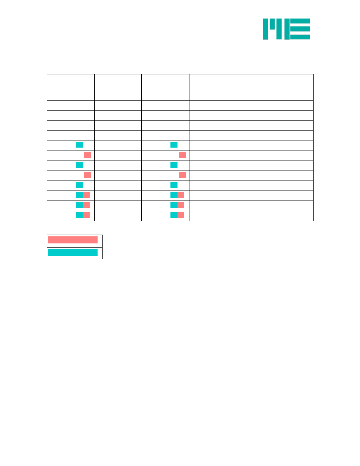
differ slightly from the set (nominal) data frequency. The grey shaded settings are
recommended as with these settings faults with a mains frequency of 50 Hz are best
suppressed by the integrated “notch filter”.
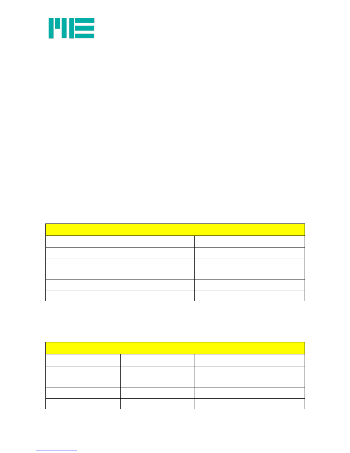
Data frequency
in Hz (nominal)
Data frequency
in Hz (effective)
Notch frequency
in Hz
-3db cut-off
frequency in Hz
(digital filter)
Parameters for “set
frequency”
500 500 7500 3003 0xAB
250 250 2000 878 0xAA
125 125 1000 441 0xA9
25 24,4 100 44.2 0xA8
15 14,7 60 26.5 0xA7
12,5.......... ........ 12,4 50 22.1 0xA6
7,5.................... 7,5 30 13.3 0xA5
6,25.......... ....... 6,25 25 11.1 0xA4
3,75....................... 3,75 15 6.63 0xA3
2,5......................... 2,5 10....... .................. 4.42 0xA2
1,25 .......... 1,25 5....... .................. 2.21 0xA1
0,625 .......... 0,625 2.5......................... 1.1 0xA0
Table 10: data frequencies and filter properties
50 Hz Notch Filter
60 Hz Notch Filter
ME-Meßsysteme GmbH
Neuendorfstr. 18a Tel.: +49 3302 89824 60 Mail: info@me-systeme.de
16761 Hennigsdorf Fax: +49 3302 89824 69 Web: www.me-systeme.de 47
Page 48

Annex
Connection figures for GSV-4BT SD and GSV-4BT LD
ME-Meßsysteme GmbH
Neuendorfstr. 18a Tel.: +49 3302 89824 60 Mail: info@me-systeme.de
48 16761 Hennigsdorf Fax: +49 3302 89824 69 Web: www.me-systeme.de
Figure 6: Straingage-Quarter bridge
Figure 7: Straingage-Half bridge
Page 49

ME-Meßsysteme GmbH
Neuendorfstr. 18a Tel.: +49 3302 89824 60 Mail: info@me-systeme.de
16761 Hennigsdorf Fax: +49 3302 89824 69 Web: www.me-systeme.de 49
Figure 8: Straingage-Full bridge
Figure 9: PT1000
Page 50

ME-Meßsysteme GmbH
Neuendorfstr. 18a Tel.: +49 3302 89824 60 Mail: info@me-systeme.de
50 16761 Hennigsdorf Fax: +49 3302 89824 69 Web: www.me-systeme.de
Figure 10: Voltage
Figure 11: Connection battery, optionally connection load 5V
Page 51

ME-Meßsysteme GmbH
Neuendorfstr. 18a Tel.: +49 3302 89824 60 Mail: info@me-systeme.de
16761 Hennigsdorf Fax: +49 3302 89824 69 Web: www.me-systeme.de 51
Page 52

Updated: 02.02.2018
Version ba-gsv4_en-v2a
Editor Holger Kabelitz
Changes Changelog Seite 52
Changelog
Version Datum Änderungen
ba-gsv4-v2 27.04.17 First Version
ba-gsv4-v2a 02.02.18 Wiring Plan for PT1000 with M12 plug
Page 53

Subject to alterations.
All information describes our products in general terms.
Made in Germany Copyright © 2018
ME-Meßsysteme GmbH
Printed in Germany
 Loading...