

Page 1

Straingage Bridge Amplifier GSV-1
Version: July 09.2007
ME-Meßsysteme GmbH Neuendorftstr. 18a Tel.: +49 3302 559 282
DE-16761Hennigsdorf Fax: +49 3302 559 141
Page 2

Table of Contents
Description.............................................................................................................................4
Models....................................................................................................................................5
Technical Data.......................................................................................................................6
Top hat rail housing GSV-1H.................................................................................................7
Pin Configuration...............................................................................................................7
Dimensions........................................................................................................................7
Adjustment of Input Sensitivity .........................................................................................8
Top Hat Rail Housing GSV-1HSW....................................................................................9
Functional Diagram.....................................................................................................10
Pin Configuration.............................................................................................................11
Adjustment of Input Sensitivity........................................................................................11
Layout of Jumpers.......................................................................................................12
Dimensions......................................................................................................................12
Option EP (cConnection of an External Potentiometer)..............................................12
Aluminum housing GSV-1A.............................................................................................14
Pin Configuration.............................................................................................................14
Adjustment of Input Sensitivity........................................................................................15
Dimensions......................................................................................................................15
Module housing GSV-1M.................................................................................................17
Dimensions......................................................................................................................17
Pin Configuration.............................................................................................................17
Printed Circuit Board GSV-1L .........................................................................................18
Pin Configuration.............................................................................................................18
Dimensions......................................................................................................................18
2 Instruction Manual
Page 3
Strain Gage Measuring Amplifier GSV-1
Instruction Manual 3
Page 4

Description
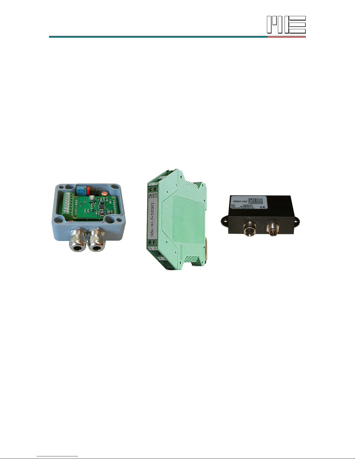
The GSV-1 is a precise bridge amplifier with an analog output for strain gage full bridges.
The special feature of the GSV-1 is the automatic zero balancing within just 90
milliseconds across 100% of the measurement range.
The zero balancing is triggered by means of a control signal from the PLC or with a
pushbutton. The control levels may be in between 3.5 and 30 volts.
The GSV-1 is available in many housing variants and many options, e.g. threshold value
sensor, peak value store, amplification selection by means of jumpers, stepless
amplification adjustment, plug connections etc.
The maximum range for the zero balancing is 100% of the sensitivity range with an output
signal ±5V at the GSV-1L. The GSV-1L with an output signal 0-10V is the zero balancing
±50% of the sensitivity range.
With options GSV-1H and GSV-1A the zero balancing accounts for ±100% of the nominal
sensitivity in every amplification level (2mV/V or 3.5mV/V).
The range for the zero balancing does not get reduced when the amplification is
increased.
The GSV-1 can supply up to 4 parallel-connected weighing cells with 350 ohm bridge
resistance each and is therefore eminently suitable for applications in weighing
technology. The option GSV-H can supply for 8 weighing cells with 350 ohm bridge
resistance.
Die Leiterkarte GSV-1L misst nur 30mm x 40mm x 6,5mm und kann aufgrund der
Stiftleisten leicht als Aufsatz in größere Leiterplatten integriert werden.
The GSV-1L printed circuit board measures just 30mm x 40mm x 6.5mm and can easily
be integrated as an add-on in larger PCBs thanks to the the pin strips.
The top hat rail housing GSV-1H for mounting rails according to EN50022 is just 12.5mm
wide and 114.5mm long.
The measuring amplifier GSV-1HSW additionally contains two threshold value sensors
with a relay and a peak value store. The thresholds are set either from front-side spindle
trimmers or connectable remote potentiometers.
The measuring amplifier GSV-1A has a robust aluminum pressure-cast housing in
environmental protection rating IP66. There is a light cast-plastic housing GSV-1M in IP66
available for portable applications.
For multi-channel applications for stress analysis with strain gages, in addition, we also
offer affordable 8-channel devices with analog outputs.
4 Instruction Manual
Page 5
Models
Characteristic data
for all versions
(basic equipment)
Voltage supply 12V or 24V DC
output signal ±5V
limiting frequency 250Hz
optionally 2.5kHz or 10kHz;
remote controllable null balancing above
2mV/V;
input sensitivity 2mV/V,
optionally 3.5mV/V or 1mV/V
GSV-1L,
GSV-1H, GSV-1HSW,
GSV-1A
GSV-1M
GSV-1T8
GSV-1A8
L-Version: Printed circuit board
LxBxH 30mm x 40mm x 6,5mm;
2 gold-plated pins, 8-pole
GSV-1L
A-Version Aluminum die-cast housing
LxBxH 64mm x 58mm x 34mm
4 amplificaiton stages (1x-2x-4x-10x) and
trimmer (1x...10x)
±5V, ±10V, 4...20mA, 0...20mA
GSV-1A
Option xV: remote
controllable amplification
switching
Option 718: plug
connection
M-Version Cast housing, IP67
cast printed circuit board in module housing
55mm x 36mm x 17mm with miniature round
plugs type 718
±5V
GSV-1M
H-Version: Top hat rail housing
BxLxH 12.5mm x 114.5mm x 99mm;
4 amplification stages (1x-2x-4x-10x) and
trimmer (1x...10x)
±5V, ±10V, 4...20mA, 0...20mA
GSV-1H
amplification switching
Option TR: stepless
amplification setting via
trimmer potentiometer
HSW-Version: Top hat rail housing
BxLxH 25mm x 114.5mm x 99mm;
4 amplification stages (1x-2x-4x-10x)
peak value store, 2 threshold values with
relay (8A), sensor output for potentiometer
setting 0...1 Volt, output signal 0...+5V
GSV-1HSW
Option EP: external
potentiometer connectable
for adjusting the threshold
values
T-Version,
8 channels
Table top housing
BxLxH 158mm x 199 x 62mm
8 measuring channels, front side 15 pole Sub
D input socket, rear side BNC socket,
external power supply, zero-setting button,
output signal ±5V
GSV-1T8
Option AD: 37-pole Sub-D
socket for connecting with
AD insertable card
A-Version,
8 channels
Aluminum portable housing, IP65
BxLxH 169mm x 100 x 52mm
8 measuring channels, front side 4 pole
sockets type 718, rear side 9-pole Coninvers
socket, external power supply, zero-setting
button, optionally with handle
output signal ±5V
GSV-1A8
Instruction Manual 5
Page 6
Technical Data
Design GSV-1 Unit
Accuracy class 0.1
Measurement range ±2
optional ±1.0 and ±3.5
mV/V
mV/V
Connectable full bridges 4 x 350 (87) up to 1 x 5000 Ohm
Bridge supply voltage 5 V
Input impedance > 20 / 300pF MOhm
Linearity deviation < 0.02 % v.E.
Temperature influence on the zero point per
10K referred to the measurement range (v.E.)
< 0.2
typ. 0.05
% v.E.
% v.E.
Temperature influence on the measuring
sensitivity per 10K referred to the measured
value (v.S.)
< 0.1
typ. 0.05
% v.S.
% v.S.
Output filter, analog output
3dB limiting frequency analog, Bessel, 2nd order 250 (20) (2k5) (10k) Hz
Resolution >20000 parts
Analog output
Nominal range
Operating range
Output resistance
optional for GSV-1H
±5
-6 ...+7.5
47
±10V, 4...20mA, 0...20mA
V
V
Ohm
Operating voltage
Nominal range
Operating range
Nominal range
GSV-1A / GSV-1A:
12.0…24
10.5...28
GSV-1L: 10,5...16 or 18...28
V
V
V
Current consumption
GSV-1L, GSV-1M
GSV-1H
GSV-1HSW
approx. 36
55...75 for option 4...20mA
approx. 90
mA
Zero balancing
Tolerance
Duration
Triggering on falling edge after at least 4ms
High-level (3,5V ... 30V or supply voltage)
< 5, typ. < 2.5
< 90
mV
ms
Memory last zero point
Nominal temperature range
Storage temperature range
-10…+65
-40…+85
°C
°C
Amplification stages
for GSV-1H and GSV-1HSW
1x, 2x, 4x, 10x (2, 1, 0.5 0.2) mV/V
Switch thresholds for GSV-1HSW
Switching hysteresis
Sensor output for potentiometer position
3 to 95
2.5
0.03...1.0
% v.E.
%v.E.
V
Peak value memory for GSV-1HSW
Rise time:
optionally for 10.000Hz:
Drift of the peak value:
< 50
< 25
< 0.1
µs/V
µs/V
%v.E./s
6 Instruction Manual
Page 7

Top hat rail housing GSV-1H
The measuring amplifier GSV-1H is available with voltage outputs ±5V, ±10V and current
output 4...20mA.
The force sensor is connected to terminals 1 to 4.
The voltage supply (11-28V) is connected to terminal 5 and 8 (ground).
For zero setting, terminal 6 is connected to the mains supply or a control signal between 5
and 24 volts is applied.
The amplification can be switched 1-2-4-10-times with internal jumpers.
If the input signal is negative, output follows up to 0mA the input signal, beyond it remains
at 0mA.
Pin Configuration
Pins
1 / 2 +U
S
−U
S
Bridge supply (for sensor input, "excitation“, "input“)
3 / 4 +U
D
−U
D
Differential input (for sensor output “output“, sensor signal)
5 / 6 +UBTara DC voltage supply
+12V or +24V
Steuereingang Nullabgleich
7 / 8 U
A
GND Analog output Masse
Note: The ground of the voltage supply is connected to terminal 8.
Dimensions
Instruction Manual 7
GSV-1H:
Depth: 114.5mm
for installation on mounting rails according to
EN50022
Page 8

Adjustment of Input Sensitivity
8 Instruction Manual
Input sensitivity can be adjusted by relocating the jumper. Input sensitivity for position 1
is given in the type designation. With position 5 amplification can be adjusted
continously by the trimmer "TR".
Position Amplification
factor
Output voltage at sensitivity
option 2 mV/V
Output voltage at sensitivity
option 3.5 mV/V
1 1
±5 volts at
±2 mV/V
±5 volts at
±3.5 mV/V
2 2
±5 volts at
±1 mV/V
±10 volts at
±2 mV/V
±5 volts at
±1.75 mV/V
±10 volts at
±3.5 mV/V
3 4
±5 volts at
±0.5 mV/V
±10 volts at
±1 mV/V
±5 volts at
±0.875 mV/V
±10 volts at
±1.75 mV/V
4 10
±5 volts at
±0.2 mV/V
±10 volts at
±0.4 mV/V
±5 volts at
±0.35 mV/V
±10 volts at
±0.7 mV/V
5 1...10
±5 volts at
±0.2...2 mV/V
±10 volts at
±0.4 ...2 mV/V
±5 volts at
±0.35...3.5 mV/V
±10 volts at
±0.7 ...3.5 mV/V
TR
Page 9

Top Hat Rail Housing GSV-1HSW
The measuring amplifier GSV-1H is equipped with a voltage output and a current output.
It is provided with two threshold switches with a relay and a very fast peak value storage
for signals up to 2.5kHz (optionally 10kHz)
The bridge excitation of the measuring amplifier (terminal 1 and 2) is connected with the
sensor input.
The differential input of the measuring amplifier (terminal 3 and 4) is connected with the
sensor output (output).
The supply voltage is connected on to terminal 11 and 8 (ground).
For automatic zero adjustment and resetting the peak value storage terminal 9 is
connected with the supply voltage or else a control signal between 5 volts and 24 volts is
fed in. In this way the zero point of the force sensor will be balanced and the peak value
storage will be reset to zero.
Through internal jumpers the amplification can be switched 1-2-4-10-times larger.
At the voltage output (terminal 6) a signal in the range between -5 volts to +10 volts is
provided.
At terminal 5 an output 4...20mA is provided.
The calibration at the plant of the GSV-1HSW is carried out optionally for the output
4...20mA (terminal 5) or for the voltage output (terminal 6),
Thresholds for relay contacts 1 and relay contacts 2 are adjusted by a front side trimmer.
The pins F1 and F2 serve for measurement of the selected threshold value or for
connection of external potentiometers if option EP was chosen.
Threshold values can be set within 3%...100% of the measurement range. Switching
Instruction Manual 9
Page 10

hysteresis is 2.5% of the measurement range.
At outputs F1 and F2 voltages of 0.03 volts up to 1 volts are detected.
Below the switching thresholds the relays are in the working state, the relay contacts are
opened. The corresponding light-emitting diodes (LED) light below the switching
thresholds.
On exceeding the thresholds or with the failure of the supply voltage UB the relay contacts
close. The exceeding of the threshold is signalled by the switching off of the LED.
Special variants as U/I-converters or peak value display with voltage input 0...5V are
optionally available.
Functional Diagram
Through the layout of jumpers two operating modes ("A" and "B") can be selected:
Mode "A" : (actual value-mode)
Signal-sequence: Amplification, peak value storage
The threshold indicator reacts to the actual value.
The actual value is shown on terminal 6.
The peak value is shown on terminal 7.
Mode "B": (Peak value-mode)
Signal-sequence: Peak value storage, amplification
The threshold indicator reacts to the peak value.
The peak value is indicated (with the amplification selected) on terminal 6.
At terminal 7 the peak value with the amplification "1" is indicated.
The maximum output voltage on the peak value display (terminal 7) is limited to 5
volts. The maximum output signal on terminal 6 amounts to +10 volts.
10 Instruction Manual
Sensor
1
2
3
4
Threshold
switch 1
Threshold
switch 2
13
14
15
16
6
4...20 mA
5
7
Peak
detector
Selectable
Gain:
1x, 2x, 4x, 10x
10
12
9 Tare
11
Power Supply
GND
8
4
5
6
1
2
3
Mode
A
B
1
2
3
4
5
6
4
5
6
1
2
3
Page 11

Pin Configuration
Terminal Designation Description
1 / 2 / 3 / 4
−U
S
+US+U
D
−U
D
bridge supply U
S
Differential input U
D
5 / 6 / 7 / 8 IA
4...20mA
UA
±5V
U
M
0..5V
GND output
signal
current
output
signal
voltage
peak value
output
Ground
9/10/11/12 Tare F1 U
B
F2 tare sensor 1 DC voltage
supply
sensor 2
13/14/15/16 K1 K1 K2 K2 Relay contacts 1 Relay contacts 2
Note: The ground of the supply voltage and the ground of the output signal are connected
to terminal 8.
Adjustment of Input Sensitivity
The input sensitivity can be adapted by displacement of the jumper. The input sensitivity for
position 1 is indicated in the type designation.
Position Input sensitivity in mV/V Amplification
factor
Output voltage
1 2 3.50 1 5 volts at 2 mV/V
2 1 1.75 2 5 volts at 1 mV/V 10 V at 2 mV/V
3 0.5 0.88 4 5 volts at 0.5 mV/V 10 V at 1 mV/V
4 0.2 0.35 10 5 volts at 0.2 mV/V 10 V at 0.4 mV/V
5 0.5...1.95 0.88...3.33 1.05...4
Instruction Manual 11
Page 12

Layout of Jumpers
Dimensions
Option EP (cConnection of an External Potentiometer)
The external potentiometers (1kOhm, 0.25 Watt) are connected between F1 or F2 and the
ground.
12 Instruction Manual
9
9
,
0
22,5
1 2 3 4
5 6 7 8
9 10 11 12
13 14 15 16
GSV-1HSW
SW 1
SW 2
SW 1
SW 2
Depth: 114.5mm;
for mounting on carrying rails according to EN50022;
On exceeding the threshold value or with the failure of
the supply voltage UB the relay contacts close.
The exceeding of the threshold value is signalled by
the switching off of the LED.
Page 13

They are for the setting of the threshold values.
Notes
a) The voltage output 0...10V is realised with the amplification level "2".
b) In the standard design the device is equipped with a Bessel-filter 2nd order, 250 Hz.
c) The calibration by the manufacturer is carried out either for the current output or for the
voltage output.
Instruction Manual 13
Page 14

Aluminum housing GSV-1A
The measuring amplifier GSV-1A is available with voltage outputs ±5V, ±10V and with
current output 4-20 mA.
The force sensor is connected to terminals 1 to 4.
The voltage supply (11-30 volts) is connected to terminal 7 and 5 (ground).
For zero setting, terminal 8 is connected to the voltage supply or a control signal between
5 volts and 24 volts is applied.
Amplification can be switched 1-2-4-10-times by means of jumpers.
Pin Configuration
Terminals
1 -UD : negative differential input
2 +UD : positive differential input
3 +US : positive bridge supply (5V)
4 -US : negative bridge supply (GND)
5 GND : ground
6 +UA : analog output
7 +UB : voltage supply (12V or 24V)
8 T: control input, zero balancing
14 Instruction Manual
Page 15

Adjustment of Input Sensitivity
Dimensions
Instruction Manual 15
The input sensitivity can be adjusted by moving the jumper. The input sensitivity for
position 1 is specified in the type designation. In position 5, the amplification can be
steplessly adjusted with the Trimmer “TR“.
Position Amplification
factor
Output voltage at sensitivity
option 2 mV/V
Output voltage at sensitivity
option 3.5 mV/V
1 1
±5 volts at
±2 mV/V
±5 volts at
±3.5 mV/V
2 2
±5 volts at
±1 mV/V
±10 volts at
±2 mV/V
±5 volts at
±1.75 mV/V
±10 volts at
±3.5 mV/V
3 4
±5 volts at
±0.5 mV/V
±10 volts at
±1 mV/V
±5 volts at
±0.875 mV/V
±10 volts at
±1.75 mV/V
4 10
±5 volts at
±0.2 mV/V
±10 volts at
±0.4 mV/V
±5 volts at
±0.35 mV/V
±10 volts at
±0.7 mV/V
5 1...10
±5 volts at
±0.2...2 mV/V
±10 volts at
±0.4 ...2 mV/V
±5 volts at
±0.35...3.5 mV/V
±10 volts at
±0.7 ...3.5 mV/V
Page 16

Option 718 (plug)
The measuring amplifier GSV-1A is also supplied with plugs of type type 718. The pin
configuration is the same as that of module housing GSV-1M.
16 Instruction Manual
Page 17

Module housing GSV-1M
The measuring amplifier GSV-1M is available with voltage outputs ±5V and 0...10V.
It is completely cast. The method of protection is IP67.
There are two 4-pole round plugs, type 718, available for connecting.
The force sensor is connected to Pin 1 to 4 or the round plug connector A (socket).
The voltage supply, the analog output and the taring input are connected to the round plug
B (pin contacts).
For zero-setting, Pin 4 is connected to the voltage supply Pin 1 or a control signal
between 5 Volt and 24 Volt is applied.
Dimensions
Pin Configuration
Instruction Manual 17
1
24
3
1
2
4
3
55
62
1
7
3
6
A
B
PIN No.
A
Spring contacts
1 +US positive bridge supply brown
2 -US negative bridge supply white
3 +UD positiver differential input blue
4 -UD negativer differential input black
B
Pin contacts
PIN No.
1 +UB supply voltage brown
2 +UA Analog output white
3 GND: ground blue
4 T. control input, null balancing black
Page 18

v: resistance for determining the input sensitivity
a: short-circuit bridge for determining the supply voltage (12V
DC or 24V DC)
Printed Circuit Board GSV-1L
Pin Configuration
St 1 St 2
1 -UD : negative differential input 1 +UB : voltage supply
2 +UD : positive differential input 2 GND : ground
3 +US : positive bridge supply 3 +5V stabilized
4 -US : negative bridge supply (GND) 4 internally reserved
5 GND : ground 5 internally reserved
6 +UA : analog output 6 optional +8 volts stabilized
7 +UB : voltage supply 7 optional –7 volts
8 T: control input zero balancing 8 T: control input, zero balancing
Dimensions
18 Instruction Manual
40,5
30
35,56
St 1
St 2
1
8
1
8
26
36
Ø2,5
Page 19

Page 20

Änderungen vorbehalten.
Alle Angaben beschreiben unsere Produkte in allgemeiner Form.
Sie stellen keine Eigenschaftszusicherung im Sinne des §459 Abs. 2, BGB, dar
und begründen keine Haftung.
Made in Germany Copyright 1999-2007
ME-Meßsysteme GmbH
 Loading...