

Page 1

R410A DC Inverter VRF V4 Plus Individual Series Side Discharge Type 50Hz MCAC-VTSM-2015-02
Part 4 Troubleshooting
1. Main PCB ports instructions ................................................................ 79
2. Main PCB parts instructions ................................ ................................ 82
3. Error code table ..................................................................................... 87
4. Troubleshooting .................................................................................... 89
78 Troubleshooting
Page 2
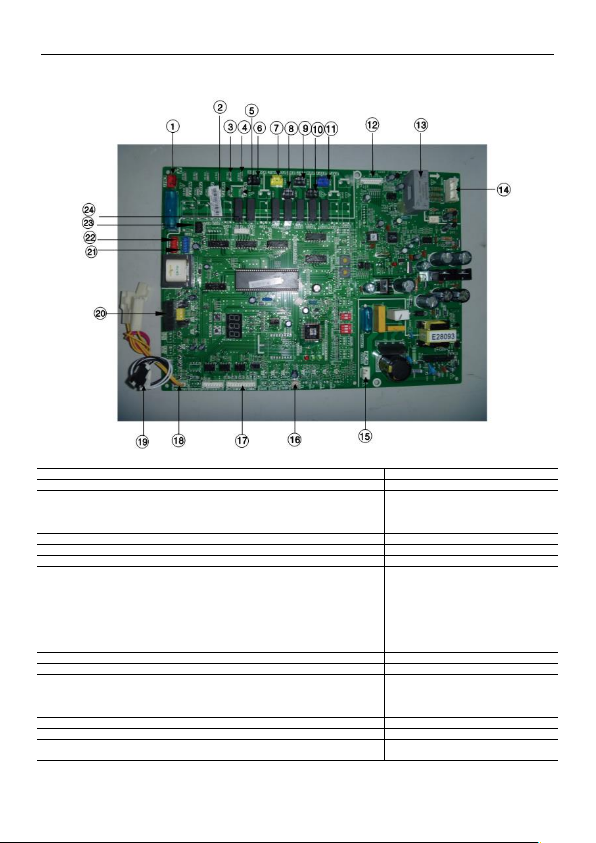
MCAC-VTSM-2015-02 R410A DC Inverter VRF V4 Plus Individual Series Side Discharge Type 50Hz
No.
Content
Port voltage
1
Power input port of the main PCB
220V
2
Load output port (crankcase heater HAET 1&HEAT 2)
220V
3
Load output port
220V
4
Load output port
220V
5
Load output port
220V
6
Load output port (solenoid valve SV6 control)
220V
7
Load output port (contactor control POWER-C port)
220V
8
Load output port (solenoid valve SV2 control)
220V
9
Load output port (solenoid valve SV7 control)
220V
10
Load output port (solenoid valve SV4 control)
220V
11
Load output port (solenoid valve ST1 control)
220V
12
Inverter module drive port
The third pin on the left: DC3.3V
Other pins: in dynamic change
13
Mutual inductor for DC main lead current inspection
In dynamic change
14
Voltage detection port of inverter module
DC540V, +15V, N
15
Power input port of the main PCB
220V
16
Discharge temperature detection port of inverter compressor
DC0~5V (in dynamic change)
17
Communication port
DC2.5~5V
18
Signal input port for high pressure and low pressure detection switch
DC0~5V (in dynamic change)
19
Outdoor ambient temperature detection port
DC0~5V (in dynamic change)
20
Current detection port
DC0~5V (in dynamic change)
21
Control port of DC fan 1
The right pin: +5V
22
Control port of DC fan 2
The right pin: +5V
23
Power output port of the main PCB
The first pin on the left: +12V
24
EXV drive port
The first pin on the left: DC12V
The other four pins: in dynamic change
1. Main PCB ports instructions
1.1 20/22.4/26kW models
Ports instructions:
Troubleshooting 79
Page 3
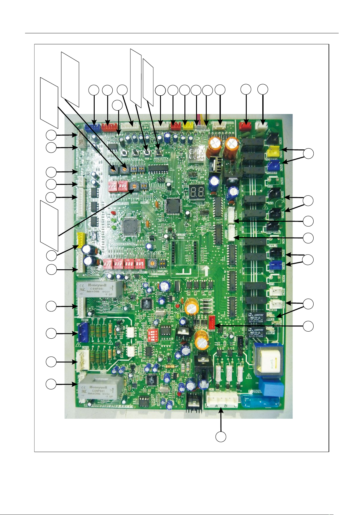
R410A DC Inverter VRF V4 Plus Individual Series Side Discharge Type 50Hz MCAC-VTSM-2015-02
1
15
12
10
7
14
13
2
3 4
5
6
88
99
11
1616
17
1819
20
21
2222
2323
2424
2525
3030
31
28
29
3030
27
26
Setting switch of
outdoor unit address
Setting switch of
outdoor unit ability
setting switch of
indoor unit quantity
Force cooling keys
Point checking keys
1.2 40/45kW models
80 Troubleshooting
Page 4
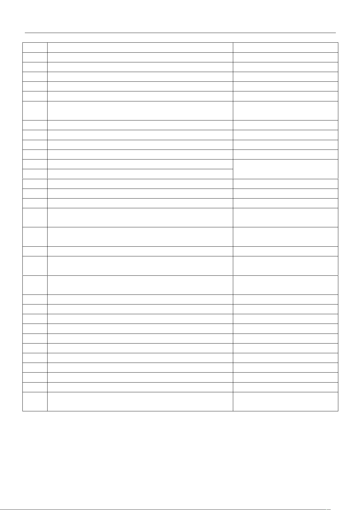
MCAC-VTSM-2015-02 R410A DC Inverter VRF V4 Plus Individual Series Side Discharge Type 50Hz
No.
Content
Port voltage
1
Discharge temp detection port of inverter compressor A
DC 0~5V (in dynamic change)
2
Discharge temp detection port of inverter compressor B
DC 0~5V (in dynamic change)
3
Temp detection port of inverter module radiator
DC 0~5V (in dynamic change)
4
Reserved
/
5
Reserved
/
6
Wiring port for communication between indoor and outdoor units, indoor
unit network and network accounting
DC 2.5~2.7V
7
Phase-sequence detection port
380V
8
Power supply port of No. 1 transformer
220V
9
Power supply port of No. 2 transformer
220V
10
Load output port
220V
11
Drive port of EXVA
The first pin on left: DC 12V
The other four pins: in dynamic change
12
Drive port of EXVB
13
Load output port
220V
14
Load output port
220V
15
Load output port
220V
16
Power output port of No.1 transformer
AC 13.5V (between upper two pins)
AC 9V (between under two pins)
17
Power output port of No.2 transformer
AC 14.5V (between upper two pins)
AC 14.5V (between under two pins)
18
Drive port of inverter module B
The third pin on left: DC 3.3V
19
Voltage detection port of inverter module B
DC 540V (between P and N),
+DC 15V (between +15V and N)
20
Voltage detection port of inverter module A
DC 540V (between P and N),
+DC 15V (between +15V and N)
21
Drive port of inverter module A
The third pin on left: DC 3.3V
22
Signal input port for system low pressure detection switch
DC 0~5V (in dynamic change)
23
Signal input port for system high pressure detection switch
DC 0~5V (in dynamic change)
24
Reserved
/
25
Reserved
/
26
Temperature detection port of ambient temp and condenser temp
DC 0~5V (in dynamic change)
27
Reserved
/
28
Control port of DC fan 1
The right pin: +5V
29
Control port of DC fan 2
The right pin: +5V
30
Current detection port of inverter compressor A and B
AC 0~7.8V (in dynamic change)
31
PCB power supply port
+5V(between GND and 5V pins)
+12V(between GND and 12V pins)
Ports instructions:
Troubleshooting 81
Page 5
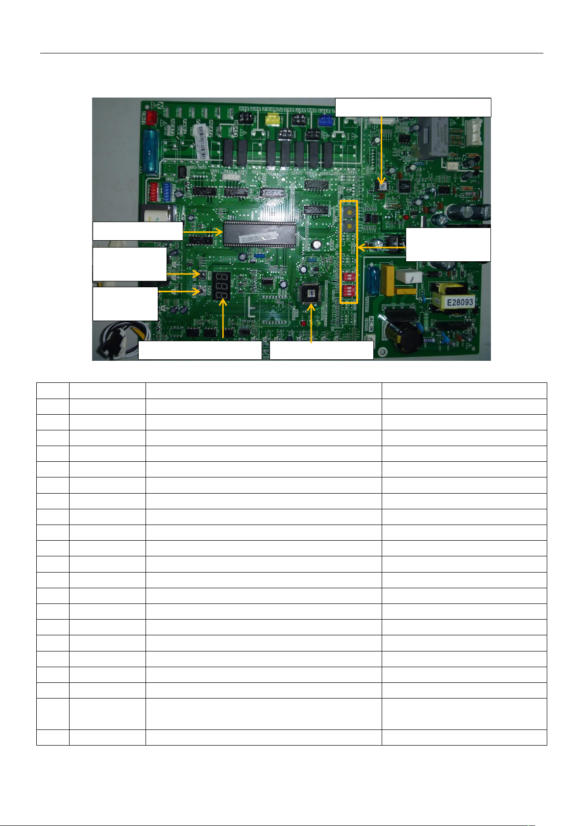
R410A DC Inverter VRF V4 Plus Individual Series Side Discharge Type 50Hz MCAC-VTSM-2015-02
No.
Display content
Display content
Note
Normal display*1
/ 1 0--
Capacity of this outdoor unit
7HP, 8HP, 10HP
2
1--
Total capacity requirements of indoor units
Actual value
3
2--
Revised total capacity requirements of outdoor unit
Actual value
4
3--
Operating mode*2
0, 2, 3, 4
5
4--
Fan speed*3
0, 1, 2, 3, 4, 5, 6, 7, 8, 9
6
5--
Average temperature of T2B/T2
Actual value
7
6--
T3 pipe temperature
Actual value
8
7--
T4 ambient temperature
Actual value
9
8--
Discharge temperature of inverter compressor
Actual value
10
9--
Discharge temperature of fixed compressor (reserved)
0
11
0--
Surface temperature of radiator (reserved)
0
12
1--
Open degree of EXV
Actual value=display×8
13
2--
Current of inverter compressor
Actual value
14
3--
Current of fixed compressor (reserved)
0
15
4--
Discharge pressure (reserved)
0
16
5--
Priority mode*4
0, 1, 2, 3, 4
17
6--
Total quantity of indoor units
Actual value
18
7--
Quantity of running units
Actual value
19
8--
The last error or protection code
Display 00 if it has no error or
protection code
20
9--
--
Check over
Inverter compressor drive chip
Main control chip
Communication chip
LED digital tube display
Function setting
dial switch
SW1: forced
cooling button
SW2: check
button
2. Main PCB parts instructions
2.1 20/22.4/26kW models
2.1.1 Check content instructions (SW2)
Note:
82 Troubleshooting
Page 6
MCAC-VTSM-2015-02 R410A DC Inverter VRF V4 Plus Individual Series Side Discharge Type 50Hz
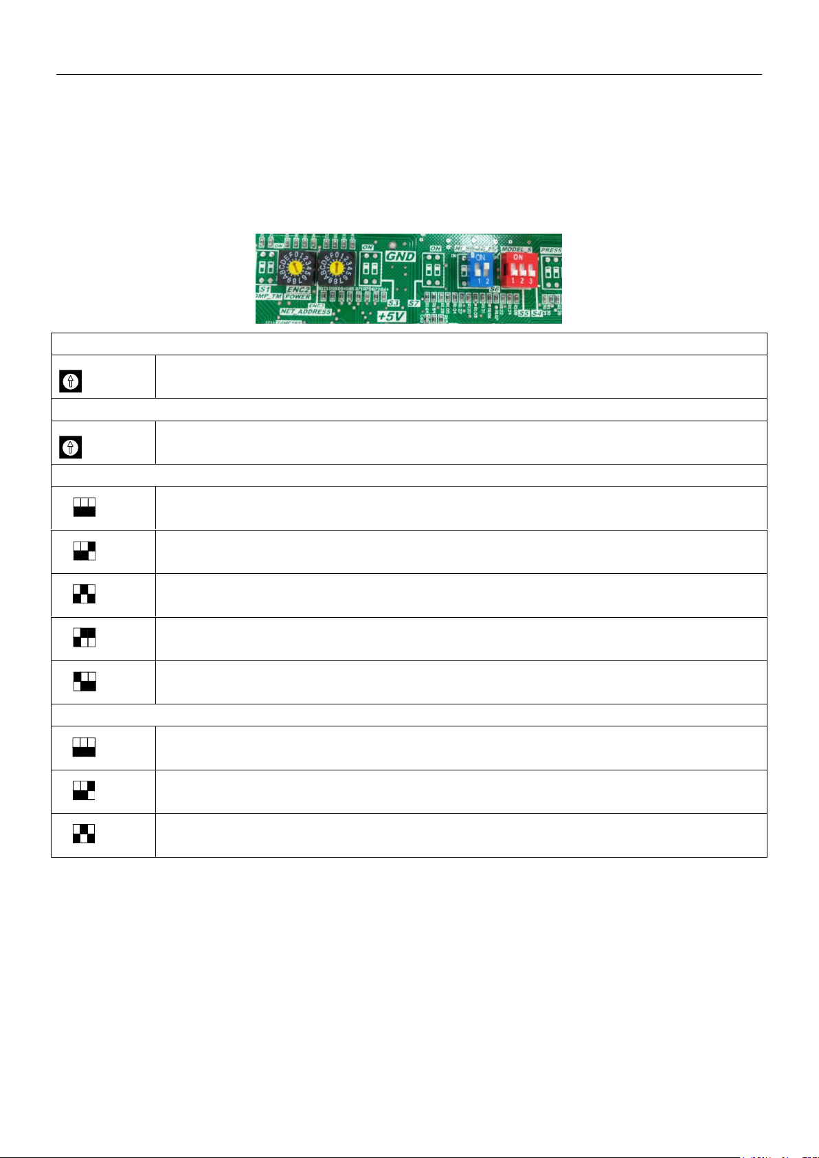
ENC2: Outdoor unit capacity setting
Outdoor unit capacity setting: 0-2 are available (capacity code0—20kW; capacity code 1—22.4kW) ; capacity
code 2—26kW)
ENC3: Quantity of indoor units setting
The quantity of indoor unit is 0-15
0~9 on ENC3 refer to 0~9 indoor units; A~F on ENC3 refer to 10~15 indoor units.
S5: Locking modes selection
Heating priority mode
(factory default)
Cooling priority mode
No.63 indoor unit running mode priority when there has No.63 indoor unit or larger capacity requirement
priority when there has on No.63 indoor unit
Only response to heating mode
Only response to cooling mode
S6: Addressing mode selection
Auto addressing mode
Manual addressing mode
(factory default)
Clean the indoor unit address
(only available for auto searching new indoor unit)
ENC2
ENC3
1 2 3
S5
ON
1 2 3
S5
ON
1 2 3
S5
ON
1 2 3
S5
ON
1 2 3
S5
ON
1 2 3
S6
ON
1 2 3
S6
ON
1 2 3
S6
ON
*1: Display compressor frequency when system is running and display the quantity of indoor unit which communicate with
outdoor unit when system is standby.
*2: Operating mode: 0 – standby mode; 2 – cooling mode; 3 – heating mode; 4 – forced cooling.
*3: Fan speed: 0 – fan stop; 1~9 – speed increase sequentially; 9 – the maximum fan speed.
*4: Priority mode: 0 – heating priority; 1 – cooling priority; 2 – first running mode priority; 3 – only respond heating mode; 4 – only
respond cooling mode.
2.1.2 System setting dial switches instructions
Troubleshooting 83
Page 7
R410A DC Inverter VRF V4 Plus Individual Series Side Discharge Type 50Hz MCAC-VTSM-2015-02
No.
Normal display
Content (present frequency)
Note
1
0.- -
Outdoor unit address
0 (individual type)
2
1.- -
Outdoor unit capacity setting
Refer to note 1
3
2.- -
Outdoor unit quantity
Reserved
4
3.- -
Setting quantity of indoor units
Actual value=display value
5
4.- -
Total capacity of outdoor units
Capacity requirement
6
5.- -
Total capacity requirement of indoor units
Actual value=display value
7
6.- -
Revised total capacity requirements of outdoor unit
Actual value=display value
8
7.- -
Running mode
Refer to note 2
9
8.- -
Actual running capacity of this outdoor unit
Capacity requirement
10
9.- -
No.1 fan speed3
Refer to note 3
11
10.- -
No.2 fan speed3
Refer to note 3
12
11.- -
T2B/T2 average temperature
Actual value=display value
13
12.- -
T3 pipe temperature
Actual value=display value
14
13.- -
T4 ambient temperature
Actual value=display value
15
14.- -
Discharge temperature of No. 1 inverter compressor
Actual value=display value
16
15.- -
Discharge temperature of No. 2 inverter compressor
Actual value=display value
17
16.- -
Reserved
/
18
17.- -
Current of No. 1 inverter compressor
Actual value=display value
19
18.- -
Current of No. 2 inverter compressor
Actual value=display value
20
19.- -
EXVA opening degree
Pulsed value=display value×8
21
20.- -
EXVB opening degree
Pulsed value=display value×8
22
21.- -
High pressure
Reserved
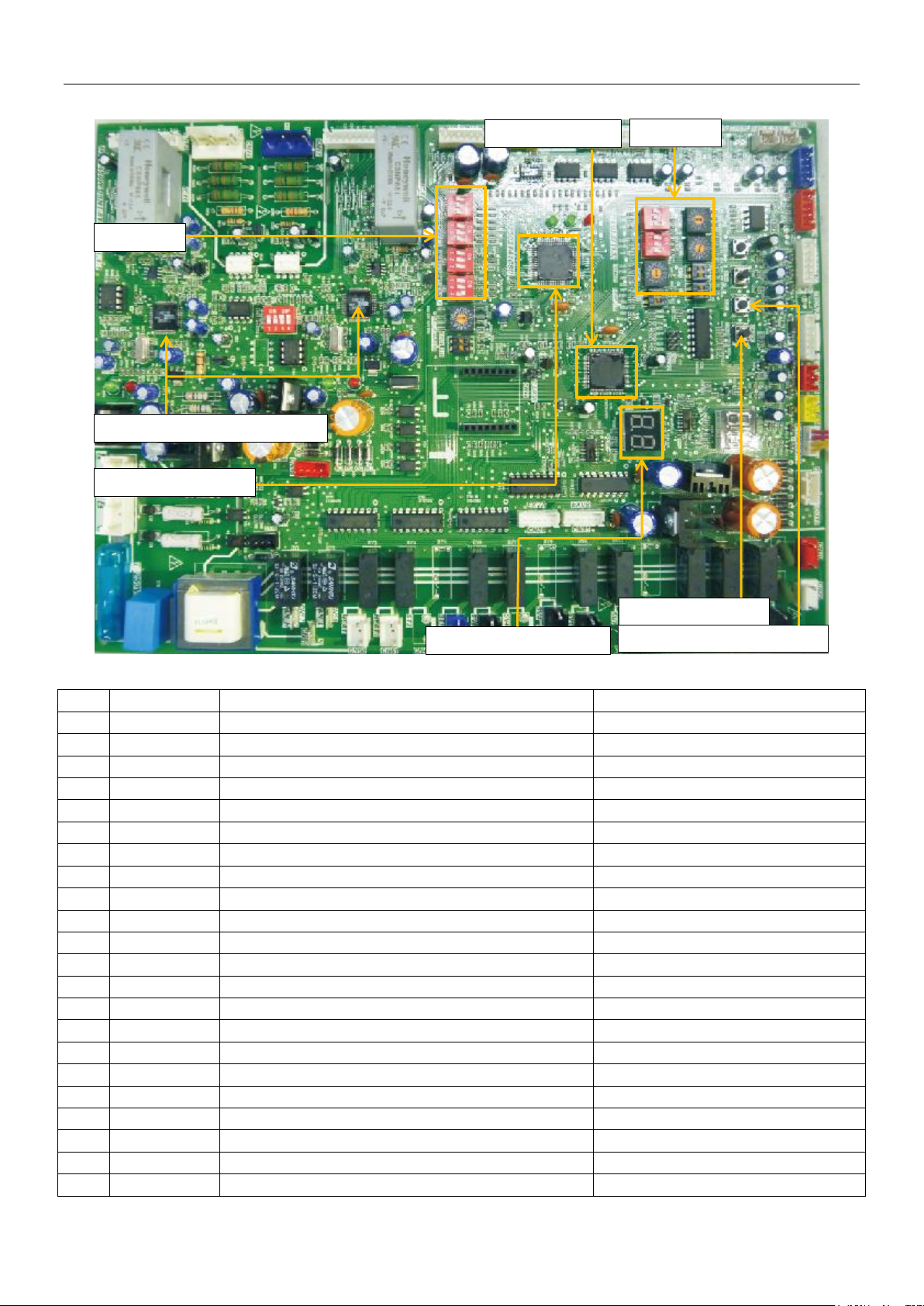
SW2: check button
SW1: forced cooling button
Dial switch
Dial switch
Inverter compressor drive chip
Main control chip
LED digital tube display
Communication chip
2.2 40/45kW models
2.2.1 Query content instructions
84 Troubleshooting
Page 8
MCAC-VTSM-2015-02 R410A DC Inverter VRF V4 Plus Individual Series Side Discharge Type 50Hz
23
22.- -
T3B / 24
23.- -
Indoor units quantity
Actual value=display value
25
24.- -
Running indoor units quantity
Actual value=display value
26
25.- -
Mode priority4
Refer to note 4
27
26.- -
Silent mode5
Refer to note 5
28
27.- -
Static pressure mode6
Refer to note 6
29
28.- -
DC voltage A
Actual value=display value×10
30
29.- -
DC voltage B
Actual value=display value×10
31
30.- -
Reserved
/
32
- -
Reserved
/
33
- -
- -
Over
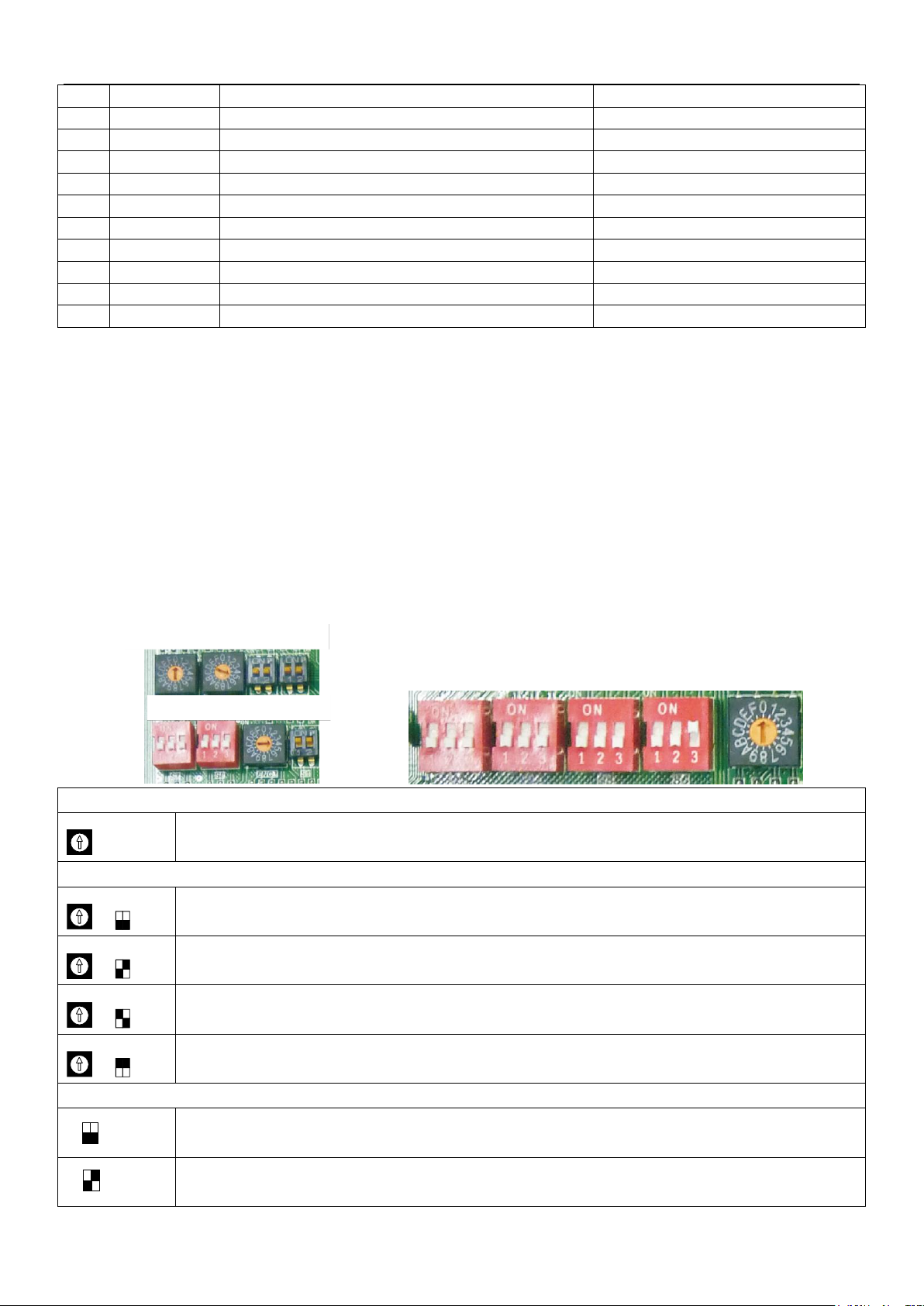
ENC2: Outdoor unit capacity setting
Outdoor unit capacity setting: 4-5 are available (capacity code4—40kW; capacity code 5—45kW)
ENC3+S12: Quantity of indoor units setting
The quantity of indoor unit is 0-15
0~9 on ENC3 refer to 0~9 indoor units; A~F on ENC3 refer to 10~15 indoor units.
The quantity of indoor unit is 16-31
0~9 on ENC3 refer to 16~25 indoor units; A~F on ENC3 refer to 26~31 indoor units.
The quantity of indoor unit is 32-47
0~9 on ENC3 refer to 32~41 indoor units; A~F on ENC3 refer to 42~47 indoor units.
The quantity of indoor unit is 48-63
0~9 on ENC3 refer to 48~57 indoor units; A~F on ENC3 refer to 58~63 indoor units.
S3: Silent mode selection
Nighttime silent mode (factory default)
Silent mode
ENC2
ENC3
S12
ON
ENC3
S12
ON
ENC3
S12
ON
ENC3
S12
ON
1 2
S3
ON
1 2
S3
ON
S3
S4
S5
S6
ENC4
ENC1
ENC3
S12
S3
S7
S8
ENC1
S1
Note:
When the outdoor unit is in standby, the LED digital tube will display the indoor unit’s quantity which can communicate with
outdoor unit, and it will display inverter compressor running frequency when there has capacity requirement.
1. Outdoor unit capacity setting: capacity code4—40kW; capacity code 5—45kW;
2. Running mode: 0—closed; 2—cooling mode; 3—heating mode; 4—forced cooling mode.
3. Fan speed: 0—closed; 1~10—fan speed increase in sequence.
4. Mode priority: 0—heating priority; 1—cooling priority; 2—No.63 indoor unit running mode priority when there has No.63 indoor
unit or larger capacity requirement priority when there has on No.63 indoor unit; 3—only response to heating; 4—only response
to cooling.
5. Silent mode: 0—nighttime silent mode; 1—silent mode; 2—reserved; 3—no silent mode.
6. Static pressure mode: 0—no static pressure; 1—low static pressure; 2—medium static pressure; 3—high static pressure.
2.2.2 System setting dial switches instructions
Troubleshooting 85
Page 9
R410A DC Inverter VRF V4 Plus Individual Series Side Discharge Type 50Hz MCAC-VTSM-2015-02
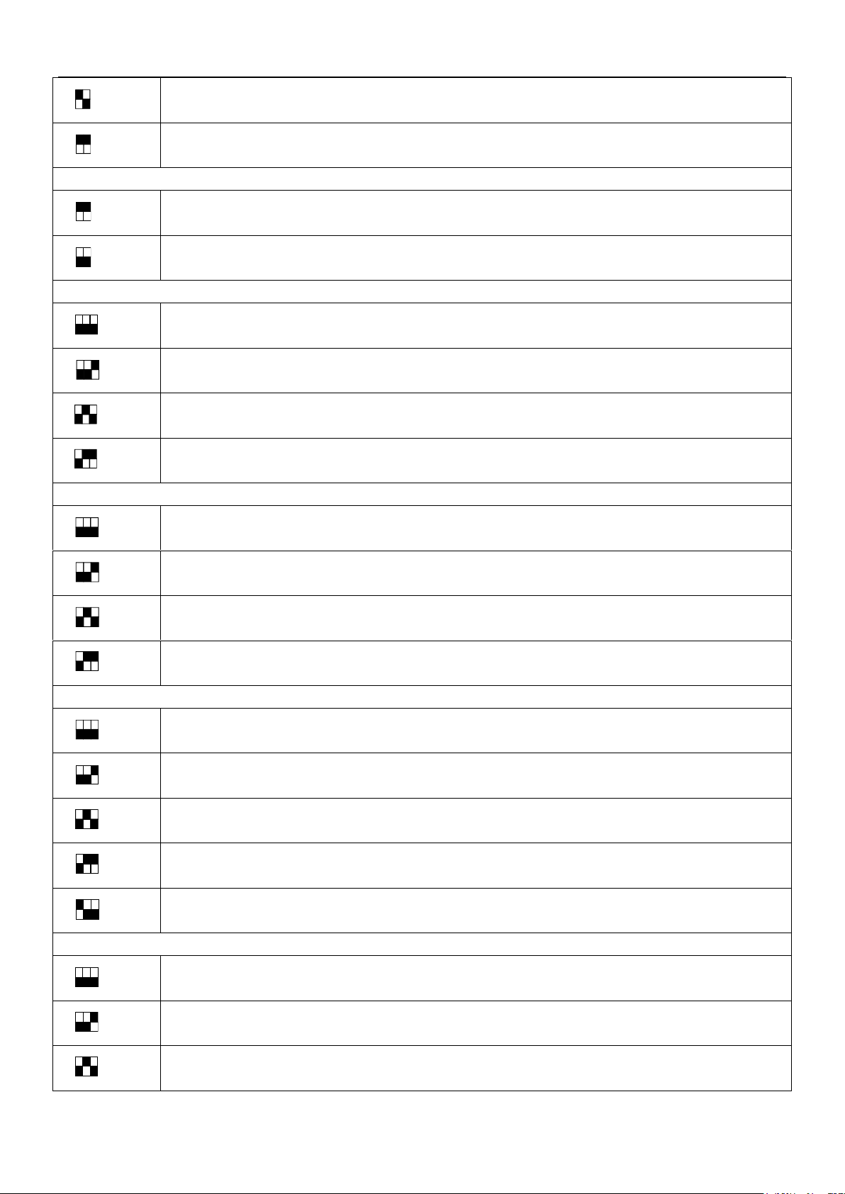
Super silent mode
No silent mode
S1: Starting time setting
Starting time is 5 minutes
Starting time is 12 minutes (factor default)
S2: Night silent time selection
Nighttime silent time 6h/10h
(factory default)
Nighttime silent time 6h/12h
Nighttime silent time 8h/10h
Nighttime silent time 8h/12h
S4: Static pressure mode selection
No static pressure mode
(factory default)
Low static pressure mode
(should be customized)
Medium static pressure mode
(should be customized)
High static pressure mode
(should be customized)
S5: Locking modes selection
Heating priority mode
(factory default)
Cooling priority mode
No.63 indoor unit running mode priority when there has No.63 indoor unit or larger capacity requirement
priority when there has on No.63 indoor unit
Only response to heating mode
Only response to cooling mode
S6: Addressing mode selection
Auto addressing mode
Manual addressing mode
(factory default)
Clean the indoor unit address
(only available for auto searching new indoor unit)
1 2
S3
ON
1 2
S3
ON
1 2
S1
ON
1 2
S1
ON
1 2 3
S2
ON
1 2 3
S2
ON
1 2 3
S2
ON
1 2 3
S2
ON
1 2 3
S4
ON
1 2 3
S4
ON
1 2 3
S4
ON
1 2 3
S4
ON
1 2 3
S5
ON
1 2 3
S5
ON
1 2 3
S5
ON
1 2 3
S5
ON
1 2 3
S5
ON
1 2 3
S6
ON
1 2 3
S6
ON
1 2 3
S6
ON
86 Troubleshooting
Page 10
MCAC-VTSM-2015-02 R410A DC Inverter VRF V4 Plus Individual Series Side Discharge Type 50Hz
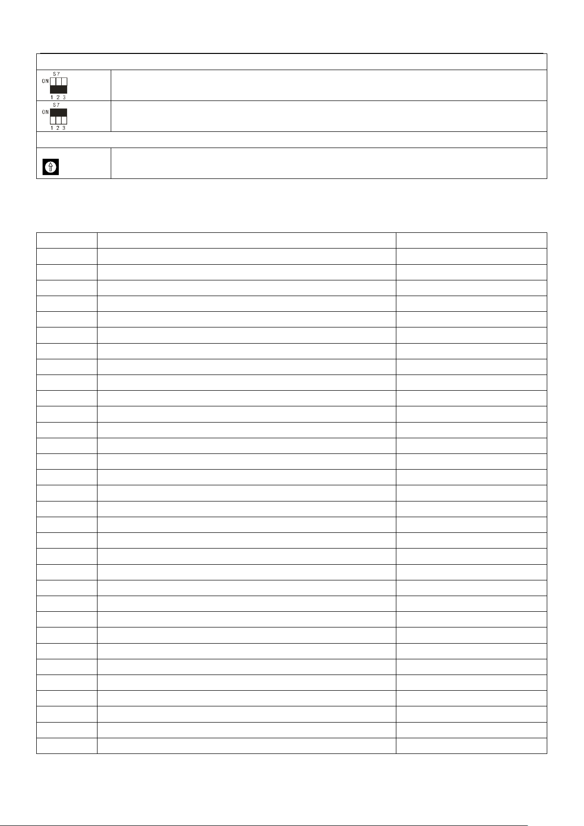
S7: ON/OFF for indoor unit quantity setting function
Indoor unit quantity setting function is open
(factory default)
Indoor unit quantity setting function is closed
ENC4: Outdoor unit network address setting
Outdoor unit network address setting (0-7 is effective)
Error code
Content
Note
E1
Reserved
E2
communication fault between the outdoor and indoor units
E4
T3 & T4 temperature sensor fault
E5
Voltage protection fault or a lack of Phase B、Phase N
E6
DC fan motor error
E7
Discharge temp sensor error
EA
A fan in the A region run for more than 5 minutes in Heat mode
EB
2 times of E6 protection in 10 minutes
H0
Communication error between main control chip and module chip
H1
Communication error between main control chip and communication chip
H4
3 times of P6 protection in 30 minutes
H5
3 times of P2 protection in 30 minutes
H7
The number of indoor units decreases
H8
Reserved
P0
Top temperature protection of inverter compressor
P1
High pressure protection
P2
Low pressure protection
P3
Current protection of inverter compressor
P4
Compressor discharge temperature protection
P5
Outdoor condenser high temperature protection
P6
Module protection (don’t display)
P8
Typhoon protection
P9
Module protection of DC fan
PE
Evaporator high temperature protection
L0
Inverter module error
L1
Low voltage protection of DC generatrix
L2
High voltage protection of DC generatrix
L3
Reserved
L4
MCE error/ synchronization/ closed loop
L5
Zero speed protection
L6
Reserved
L7
Phase sequence error
ENC4
3. Error code table
3.1 20/22.4/26kW models
Troubleshooting 87
Page 11
R410A DC Inverter VRF V4 Plus Individual Series Side Discharge Type 50Hz MCAC-VTSM-2015-02
L8
Frequency difference in one second more than 15Hz protection
L9
Frequency difference between the real and the setting frequency more
than 15Hz protection
Error code
Content
Note
E1
Phase protection
E2
Indoor units and master unit communication error
E4
Pipe temp T3/ambient temp T4 sensor error
E5
Voltage error
E6
DC fan motor error
E7
Discharge temp sensor error
EA
T3 pipe temperature protection in heating mode
EB
E6 protection appears twice in 10 minutes
H0
Communication error between main control chip and module chip
H1
Communication error between main control chip and communication chip
H4
P6 protection appears three times in 60 minutes
H5
P2 protection appears three times in 60 minutes
H6
P4 protection appears three times in 100 minutes
H7
Quantity of indoor units decrease
H8
High pressure sensor error
H9
P9 protection appears three times in 60 minutes
P0
Top temperature protection of inverter compressor
P1
High pressure protection
P2
Low pressure protection
P3
Current protection of inverter compressor
P4
Discharge temperature protection
P5
Pipe temperature protection
P6
Module protection (don’t display)
P8
Typhoon protection
P9
Module protection of DC fan
PL
Temperature protection of inverter module
C7
PL protection appears three times in 60 minutes
L0
Inverter module error
L1
Low voltage protection of DC generatrix
L2
High voltage protection of DC generatrix
L3
Reserved
L4
MCE error/ synchronization/ closed loop
L5
Zero speed protection
L6
Reserved
L7
Phase sequence error
L8
Frequency difference in one second more than 15Hz protection
L9
Frequency difference between the real and the setting frequency more
than 15Hz protection
3.2 40/45kW models
88 Troubleshooting
Page 12
MCAC-VTSM-2015-02 R410A DC Inverter VRF V4 Plus Individual Series Side Discharge Type 50Hz
Error code
Content
r1
Lack of refrigerant
r2
Obvious lack of refrigerant
r3
Serious lack of refrigerant
R1
Too much refrigerant
R2
Serious too much refrigerant
E1: Phase sequence error
The 3-phase sequence of power supply is
wrong. (The A, B, C terminal of three-phase
power supply should meet compressor phase
sequence requirement. If the phase
sequence is adverse, the compressor will
operate inversely.
Exchange any two of the
3-sequence
Some power supply terminals are
loose, if there has phase loose, the
compressor will operate abnormally,
and the current is very large
Fasten each phase joint of
power supply.
Outdoor main control
board is damaged
Replace the outdoor
main control board
No
No
Yes
Yes
Note: P6, L0~L9 error codes can’t display on digital tube automatically, these error codes will display on digital tube only through
SW3 button (press SW3 ten times, every one second for a time)
The large capacity V4+ individual system (56-90kW) have the function of refrigerant volume automatic
judgment.
When all the indoor units are in cooling or heating mode, the system will be in refrigerant volume judgment
mode automatically. If the system judges that the refrigerant volume is normal, the system will operate normally,
no error code will display. If the system judges that the refrigerant volume is abnormal, corresponding error
code will display on digital tube.
When only partial indoor units are in cooling or heating mode, the system will not judge the refrigerant volume
and the digital tube will reserve the last judging result.
4. Troubleshooting
4.1 E1: Phase sequence error
Note:
If the wiring connection of each outdoor unit is according to A, B, C phase sequence, when the quantity of outdoor units is large,
the current difference between C phase and A, B phase will be very large for the power supply load of each outdoor unit is on C
phase, it is very easy to lead to air switch break and wiring terminal burnout. So when the quantity of outdoor units is large, the
phase sequence should be staggered, then the current can be distributed to the three phases equally.
Troubleshooting 89
Page 13
R410A DC Inverter VRF V4 Plus Individual Series Side Discharge Type 50Hz MCAC-VTSM-2015-02
E2: Indoor units and outdoor
unit communication error
Communication wires P, Q, E are
short circuit or disconnected (Measure
the resistance among P Q and E, the
normal resistance is 120Ω)
Reconnect the communication
wires
Communication wires are not
connected in line shape
The communication wires are interfered
by high voltage power (voltage over
220V is high voltage power)
Communication wires are close to
electromagnetic interference source.
Such as transfer, strong fluorescent
lamp, etc.
Remove the interference source, or
use device to filter out the interference
The length of communication wire is
over 1200m
Adjust the wire length to less than
1200m or strengthen the signal
Yes
Yes
Yes
Connect the communication wires
in line shape
No
No
No
No
No
Yes
Ensure the communication wires and
high voltage wires do not twining
Yes
Outdoor main control
board is damaged
Replace the outdoor
main control board
4.2 E2: Indoor units and outdoor unit communication error
90 Troubleshooting
Page 14
MCAC-VTSM-2015-02 R410A DC Inverter VRF V4 Plus Individual Series Side Discharge Type 50Hz
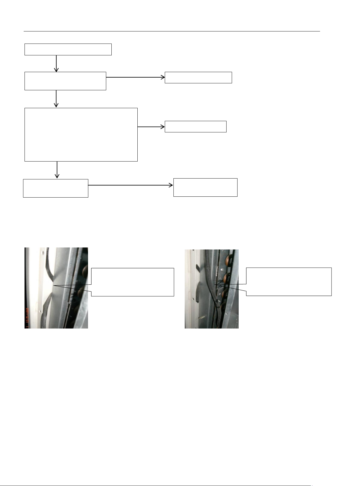
E4: T3/T4/T7 sensor error
T3/T4/T7 port on main
control board is loose
Fasten the T3/T4 port
T3/T4/T7 sensor is short circuit or
disabled (Using a multimeter to
measure resistance, if the resistance is
too small, the sensor is short circuit, if
the resistance in certain temperature is
not consistent with attached table 1(2),
the sensor is disabled)
Replace the sensor
No
No
Yes
Yes
connected with sheet metal
After being reconnected, the
Outdoor main control
board is damaged
Replace the outdoor
main control board
4.3 E4: Pipe temp T3/ambient temp T4 sensor error; E7: Discharge temp sensor T7 error
Case: There is no display on main control board, and the problem still exists after replacing main control board.
Voltage values on measuring plate (such as 220V, 5V, 12V, etc.) are normal; after measuring resistance value
of sensor, find that T4 thermo-bulb is earth-continuity, and further discover that the thermal cable of T4
sensor is punched by bolt, as follows:
T4 sensor is worn out and
Troubleshooting 91
system becomes normal
Page 15
R410A DC Inverter VRF V4 Plus Individual Series Side Discharge Type 50Hz MCAC-VTSM-2015-02
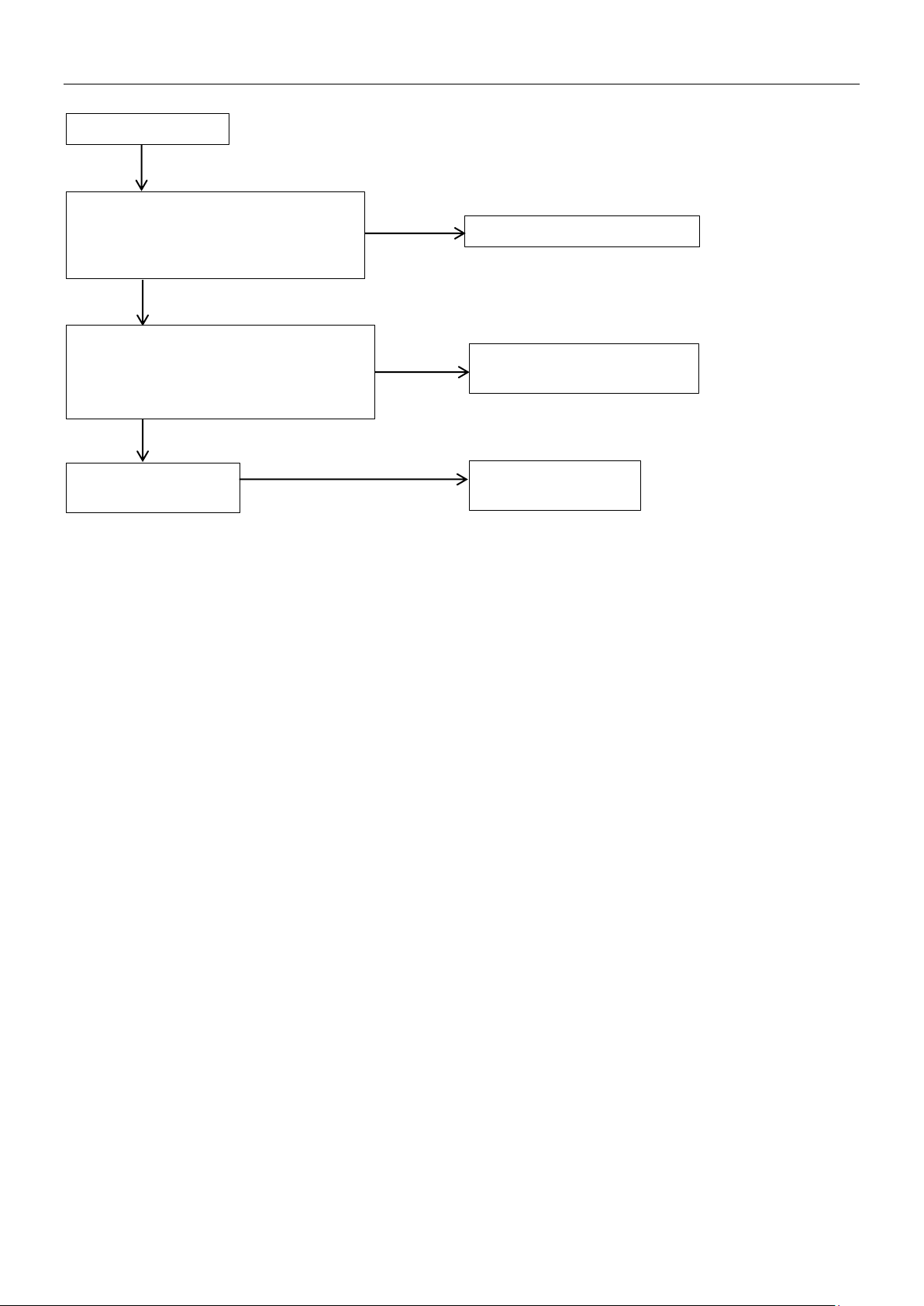
E5: Voltage error
Voltage of power supply is too high or
too low (the normal voltage between A
and N (B and N, C and N) should be
163V~268V)
Provide normal power supply
Check the high voltage circuit. Whether
, fan
, inverter module
is output error③, etc.
Replace the inverter module
or repair related parts
No
No
Yes
Yes
Outdoor main control
board is damaged
Replace the outdoor
main control board
4.4 E5: Voltage error
the compressor is short circuit①
motor is short circuit②
Note:
1. How to check whether the compressor is short circuit①:
The normal resistance value of inverter compressor among U V W is 0.7~1.5Ω, and infinity to earth. If the resistance value is out
of the range, the compressor is abnormal.
2. How to check whether the fan motor is short circuit②:
The normal value of DC fan motor coil among U V W is less than 10Ω, and the value of AC fan motor coil is from a few ohm to
hundreds of ohm for different fan motor model. If the measured value is 0Ω, the fan motor is short circuit.
3. How to check whether the inverter module is output error③:
Dial the multimeter to diode file, black pen on P and red pen respectively on U,V,W, if the multimeter displays 0.4~0.7 V, it is
normal; Red pen on N, black pen respectively on U,V,W, if the multimeter displays 0.4~0.7 V, it is normal. Satisfying the above
two conditions at the same time indicates that the inverter module has no problem.
92 Troubleshooting
Page 16
MCAC-VTSM-2015-02 R410A DC Inverter VRF V4 Plus Individual Series Side Discharge Type 50Hz
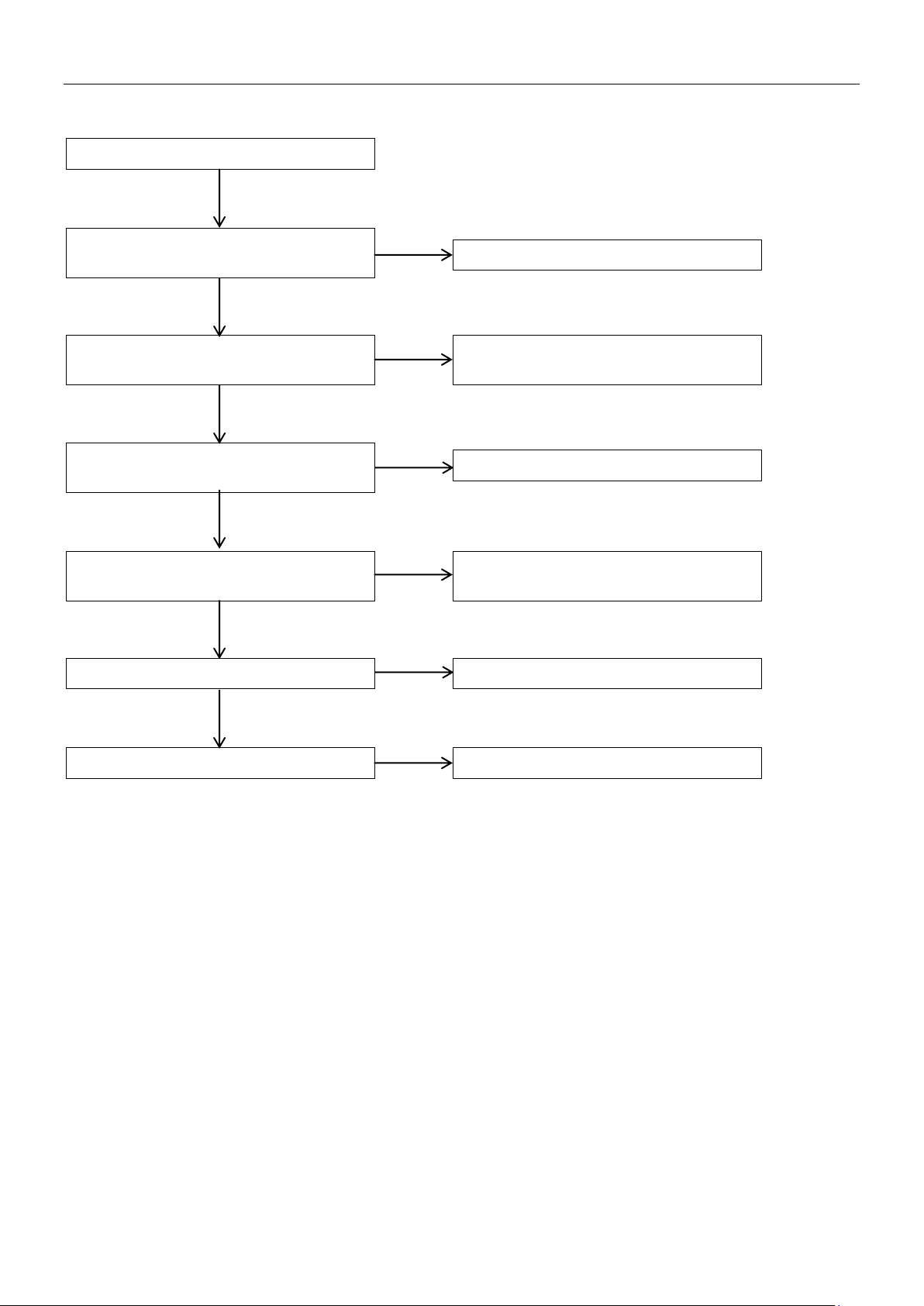
E6: DC fan motor error
There has strong airflow against fan
wheel when the fan is running
It belongs to normal protection
DC fan wiring connection is not
consistent with wiring nameplate
Wiring connection consists with wiring
nameplate
The voltage between PN of the fan
transfer board is not for 255V to 367V
The fuse on the filter is disconnected or
damaged
Reconnect the fuse or replace the fuse
Insure the power supply is 380-415V,
3N, 50Hz
Outdoor main control board is damaged
Replace the outdoor main control board
Fan motor is damaged
Replace the fan motor
No
No
No
No
No
Yes
Yes
Yes
Yes
Yes
Yes
4.5 E6: DC fan motor error; EB: E6 protection appears twice in 10 minutes
Troubleshooting 93
Page 17
R410A DC Inverter VRF V4 Plus Individual Series Side Discharge Type 50Hz MCAC-VTSM-2015-02
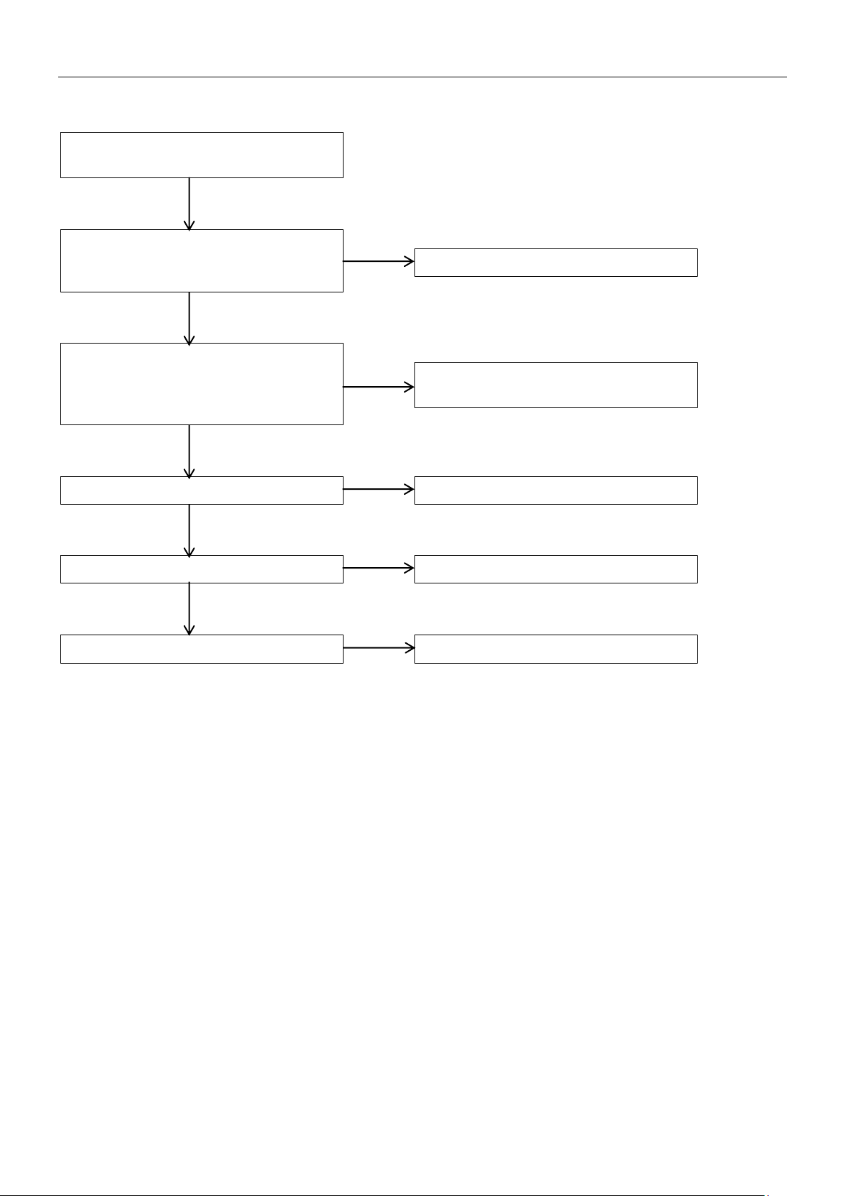
EA: T3 pipe temperature protection
in heating mode
The outdoor ambient temperature is
higher than the unit operating limitation
in heating mode
It belongs to normal protection
System is lack of refrigerant①.
(Refrigerant recharging is not according
refrigerant leakage)
Add refrigerant or check up the leakage
of the system
Outdoor heat-exchanger is blocked
Remove the obstacle
T3 temperature sensor is damaged
Replace the temperature sensor
Outdoor main control board is damaged
Replace the outdoor main control board
Yes
Yes
Yes
Yes
Yes
No
No
No
No
4.6 EA: T3 pipe temperature protection in heating mode
When T3 pipe temperature exceeds 27oC lasting for five minutes in heating mode, the unit will display EA error.
to the requirement, or there has
1. The phenomenon of lack of refrigerant②:
Top temperature and discharge temperature of all compressors are higher than normal value, discharge pressure and suction
pressure are both lower than normal value, current is lower than normal value, suction pipe may be frosting. All the phenomenon
will disappear after recharging refrigerant.
94 Troubleshooting
Page 18
MCAC-VTSM-2015-02 R410A DC Inverter VRF V4 Plus Individual Series Side Discharge Type 50Hz
H0/H1
Power supply for main PCB,
transformer 1 and transformer 2
terminals are abnormal①
The transformer on main control board
is disabled②
Remove the interference
There has electromagnetic interference
nearby the unit. Such as
High-frequency transmitter or other
high strength radiation device
Replace the transformer
Provide normal power supply
Outdoor main control board is damaged
Replace the outdoor main control board
No
No
No
Yes
Yes
Yes
Yes
4.7 H0: Communication error between main control chip and module chip; H1: Communication error
between main control chip and communication chip
Note:
1. How to check whether power supply of main PCB, transformer 1 and transformer 1 terminals are abnormal①
The voltage of power supply for transformer 1 and transformer 1 terminals are both 220V, the voltage between ―GND‖ and ―+5V‖
terminals of Power supply for main PCB ports is 5V, and between ―GND‖ and ―+12V‖ terminals of Power supply for main PCB
ports is 12V.
2. How to check whether the transformer on main control board is disabled②
The voltage of power supply for transformer 1 and transformer 2 terminals are both 220V, the voltage of transformer 1 output
terminals is AC9V (between left two pins) and AC13.5V (between rights two pins); the voltage of transformer 2 output terminal is
AC14.5V (between left two pins) and AC 14.5V (between rights two pins). If the voltage is out of the range, the transformer is
disabled.
Troubleshooting 95
Page 19
R410A DC Inverter VRF V4 Plus Individual Series Side Discharge Type 50Hz MCAC-VTSM-2015-02
H7: Quantity of indoor units
decrease error
Communication terminals P Q E
are loose
Fasten the communication
terminals
Yes
Transformer of IDU is disabled①
Replace the transformer
IDU are not unified power supply*
Insure all the IDU be unified
power supply
485 communication IC is disabled②
IDU PCB is disabled
Replace the IDU PCB
No
No
No
No
Yes
Yes
Some IDU are assigned the
same address
Some IDU are power off
Set the IDU addresses differently
Power on all IDU
No
No
Yes
Yes
P Q E terminals
4.8 H7: Quantity of indoor units decrease error
H7 error will display when the quantity of indoor units decrease above 3 minutes.
Note:
1. How to check whether the transformer of IDU is disabled①
The voltage input for IDU transformer is 220V, the voltage output of is AC9V (yellow-yellow) and AC13.5V (brown-brown)
2. How to check whether the 485 communication IC is disabled②
The normal voltage between ―P‖ and ―GND‖ is DC2.5~2.7V, between ―Q‖ and ―GND‖ is DC2.5~2.7V. If the voltage is out of the
normal range, the 485 communication IC is disabled.
*Indoor units should be unified power supply, which can prevent compressor from liquid hammer caused by dropped indoor units
with EXV unclosed.
96 Troubleshooting
Page 20
MCAC-VTSM-2015-02 R410A DC Inverter VRF V4 Plus Individual Series Side Discharge Type 50Hz
High pressure sensor is
short circuit or disabled①
Replace the sensor
System is lack of refrigerant②.
leakage)
Add refrigerant or check up
the leakage of the system
The low pressure side is blocked③
closed strop valve, dirty filter, etc.
Make sure all valves are open, clean
the system should be clean
Yes
The heat exchange of evaporator
of the air outlet, etc.
Check the system and
fixed up the error
No
No
No
No
No
H8: High pressure sensor error
High pressure sensor connection
port on main control board is loose
Fasten the connection port
Yes
Yes
Yes
Yes
Outdoor main control
board is damaged
Replace the outdoor
main control board
4.9 H8: High pressure sensor error
When the discharge pressure is lower than 0.3MPa, the system will display H8 error, the ODU in standby.
When the discharge pressure is back to normal, H8 disappears and normal operation resumes.
(Refrigerant recharging is not
according to the requirement,
or there has refrigerant
for squashed pipe, closed EXV,
the filter, if the filter is blocked by ice,
is not good. It may be caused by
dirty heat changer, abnormal IDU
fan running, some barrier in front
Note:
1. How to check whether the high pressure sensor is short circuit or disabled①
Measure the resistance among the three terminals of the pressure sensor, if the resistance value is megohm or infinite, the
pressure sensor is disabled, otherwise, it may be normal.
2. The phenomenon of lack of refrigerant②:
Top temperature and discharge temperature of all compressors are higher than normal value, discharge pressure and suction
pressure are both lower than normal value, current is lower than normal value, suction pipe may be frosting. All the phenomenon
will disappear after recharging refrigerant.
3. The phenomenon of the low pressure side is blocked③:
The discharge temperature is higher than normal value*, low pressure is lower than normal value*, current is lower than normal
value* and suction pipe may be frosting.
*The normal system running parameters please refer to attached table 3.
Troubleshooting 97
Page 21
R410A DC Inverter VRF V4 Plus Individual Series Side Discharge Type 50Hz MCAC-VTSM-2015-02
P1: High pressure protection
The heat exchange of condenser
dirty heat changer, abnormal ODU
each other, etc.
Check the system and
fixed up the error
The high pressure side of the system is
valve or closed stop valve
Make sure all valves are open,
the obstacle
Refrigerant is excess②
Discharge part of the refrigerant. Add
some oil if it leaks during the discharge
System contains air or nitrogen③
Discharge the entire refrigerant. Then
Add oil to the system if it leaks.
Yes
No
No
No
No
Yes
Yes
Yes
Outdoor main control
board is damaged
Replace the outdoor
main control board
4.10 P1: High pressure protection
When the pressure is over 4.4MPa, the system will display P1 protection, the ODU in standby. When the
pressure is lower than 3.2MPa, P1 disappears and normal operation resumes.
is not good. It may be caused by
fan running, ODU are too near to
blocked① for squashed pipe, blocked
check the system, and remove
vacuum the system and refill the refrigerant.
Note:
1. The phenomenon of The high pressure side of the system is blocked①:
The high pressure is higher than normal value, the low pressure is lower than normal value, and the discharge temperature is
higher than normal value.
2. The phenomenon of the refrigerant is excess②:
The high pressure is higher than normal value, the low pressure is higher than normal value, and the discharge temperature is
lower than normal value.
3. The phenomenon of the system contains air or nitrogen③:
The high pressure is higher than normal value, current is larger than normal value, discharge temperature is higher than normal
value, compressor makes noise, pressure meter do not display steady.
*The normal system running parameters please refer to attached table 3.
*If the system install three-phase protector, and the three-phase protector connect with high pressure switch in series connection,
the system will display P1 protection when fist power on, and P1 protection will disappear after system is steady.
*If the system install three-phase protector, and the three-phase protector connect with low pressure switch in series connection,
the system will display P2 protection when fist power on, and P2 protection will disappear after system is steady.
4.11 P2/H5: Low pressure protection
When the pressure is lower than 0.05MPa, the system will display P2 protection, the ODU in standby. When
the pressure is higher than 0.15MPa, P2 disappears and resumes normal operation.
H5 error will display when system appear 3 times P2 protection in 60 minutes, it cannot resume automatically,
and it can resume only by restarting the machine.
98 Troubleshooting
Page 22
MCAC-VTSM-2015-02 R410A DC Inverter VRF V4 Plus Individual Series Side Discharge Type 50Hz
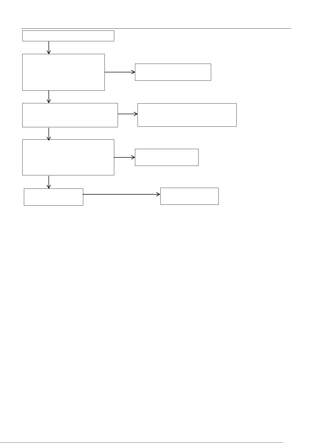
P2/H5: Low pressure protection
System is lack of refrigerant①.
leakage)
Add refrigerant or check up
the leakage of the system
The low pressure side is blocked②
closed strop valve, dirty filter, etc.
Make sure all valves are open, clean
the system should be clean
Yes
Yes
The heat exchange of evaporator
of the air outlet, etc.
Check the system and
fixed up the error
Yes
No
No
No
Outdoor main control
board is damaged
Replace the outdoor
main control board
(Refrigerant recharging is not
according to the requirement,
or there has refrigerant
for squashed pipe, closed EXV,
the filter, if the filter is blocked by ice,
is not good. It may be caused by
dirty heat changer, abnormal IDU
fan running, some barrier in front
Note:
1. The phenomenon of lack of refrigerant①:
Top temperature and discharge temperature of all compressors are higher than normal value, discharge pressure and suction
pressure are both lower than normal value, current is lower than normal value, suction pipe may be frosting. All the phenomenon
will disappear after recharging refrigerant.
2. The phenomenon of the low pressure side is blocked②:
The discharge temperature is higher than normal value*, low pressure is lower than normal value*, current is lower than normal
value* and suction pipe may be frosting.
*The normal system running parameters please refer to attached table 3.
*If the system install three-phase protector, and the three-phase protector connect with high pressure switch in series connection,
the system will display P1 protection when fist power on, and P1 protection will disappear after system is steady.
*If the system install three-phase protector, and the three-phase protector connect with low pressure switch in series connection,
the system will display P2 protection when fist power on, and P2 protection will disappear after system is steady.
Troubleshooting 99
Page 23
R410A DC Inverter VRF V4 Plus Individual Series Side Discharge Type 50Hz MCAC-VTSM-2015-02
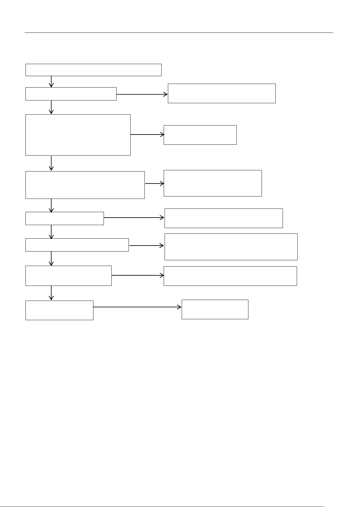
P3: Compressor current protection
The indoor load is too large①
Make sure the ratio of connectable
IDU is less than 130% or add ODU
No
Yes
The heat exchange of condenser
dirty heat changer, abnormal ODU
each other, etc.
Check the system and
fixed up the error
No
Yes
The high pressure side of the system is
valve or closed stop valve
Make sure all valves are open,
the obstacle
Refrigerant is excess③
Discharge part of the refrigerant. Add
some oil if it leaks during the discharge
System contains air or nitrogen④
Discharge the entire refrigerant. Then
Add oil to the system if it leaks.
Yes
No
No
Yes
Yes
High voltage short circuit or
compressor error⑤
Make sure the high voltage circuit is normal,
or replace the compressor
Yes
No
No
Outdoor main control
board is damaged
Replace the outdoor
main control board
4.12 P3: Current protection of inverter compressor
P3: When the current of inverter compressor is over12A, the system will display P3 protection, the ODU in
standby. When the current goes back to normal range, P3 disappears and normal operation resumes.
is not good. It may be caused by
fan running, ODU are too near to
blocked② for squashed pipe, blocked
check the system, and remove
vacuum the system and refill the refrigerant.
Note:
1. The phenomenon of the indoor load is too large①:
The suction temperature and discharge temperature are both higher than normal value.
2. The phenomenon of The high pressure side of the system is blocked②:
The high pressure is higher than normal value, the low pressure is lower than normal value, and the discharge temperature is
higher than normal value.
3. The phenomenon of the refrigerant is excess③:
The high pressure is higher than normal value, the low pressure is higher than normal value, and the discharge temperature is
lower than normal value.
4. The phenomenon of the system contains air or nitrogen④:
The high pressure is higher than normal value, current is larger than normal value, discharge temperature is higher than normal
value, compressor makes noise, pressure meter do not display steady.
5. How to check whether compressor is error⑤:
Measure the resistance between two terminals among the three terminals of compressor. The resistance between two terminals
is 2-5Ω, the resistance between each terminal and ground is infinity, if the resistance is out of the normal range, the compressor
100 Troubleshooting
Page 24
MCAC-VTSM-2015-02 R410A DC Inverter VRF V4 Plus Individual Series Side Discharge Type 50Hz
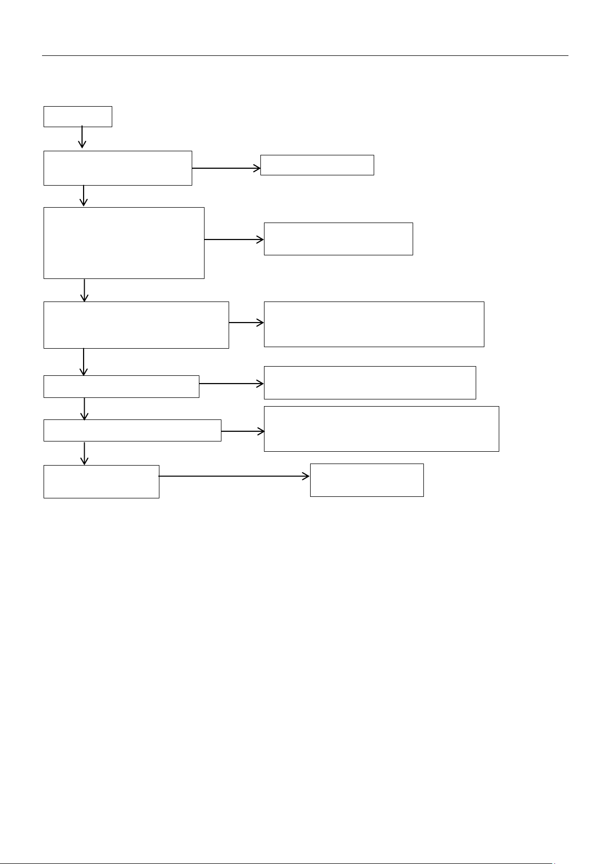
P4/H6
System is lack of refrigerant②.
leakage)
Add refrigerant or check up
the leakage of the system
The low pressure side is blocked③
closed strop valve, dirty filter, etc.
Make sure all valves are open, clean the
system should be clean
The indoor load is too large④
Make sure the ratio of connectable IDU is
less than 130% or add ODU
System contains air or nitrogen⑤
Discharge the entire refrigerant. Then vacuum
the system if it leaks.
T7C2/T7C3/T7C4 sensor is
short circuit or disabled①.
Replace the sensor
Yes
No
No
No
No
No
Yes
Yes
Yes
Yes
Outdoor main control
board is damaged
Replace the outdoor
main control board
is error.
*The normal system running parameters please refer to attached table 3.
4.13 P4: Discharge temperature protection; H6: P4 protection appears three times in 100 minutes
(Refrigerant recharging is not
according to the requirement,
or there has refrigerant
for squashed pipe, closed EXV,
filter, if the filter is blocked by ice, the
the system and refill the refrigerant. Add oil to
Note:
H6 error cannot resume automatically, and it can resume only by restarting the machine.
1. How to check whether the T7C2/T7C3/T7C4 sensor is short circuit or disabled①:
Using a multimeter to measure resistance, if the resistance is too small, the sensor is short circuit, if the resistance in certain
temperature is not consistent with attached table 2, the sensor is disabled
2. The phenomenon of lack of refrigerant②:
Top temperature and discharge temperature of all compressors are higher than normal value, discharge pressure and suction
pressure are both lower than normal value, current is lower than normal value, suction pipe may be frosting. All the phenomenon
will disappear after recharging refrigerant.
3. The phenomenon of the low pressure side is blocked③:
The discharge temperature is higher than normal value*, low pressure is lower than normal value*, current is lower than normal
value* and suction pipe may be frosting.
4. The phenomenon of the indoor load is too large④:
The suction temperature and discharge temperature are both higher than normal value.
5. The phenomenon of the system contains air or nitrogen⑤:
The high pressure is higher than normal value, current is larger than normal value, discharge temperature is higher than normal
value, compressor makes noise, pressure meter do not display steady.
*The normal system running parameters please refer to attached table 3.
4.14 P5: Condenser temperature protection
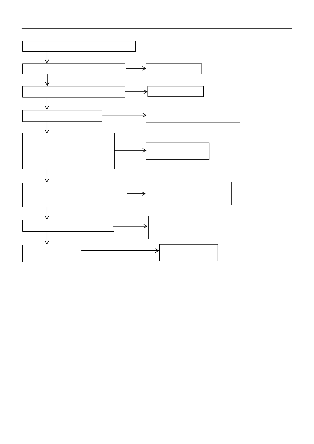
When condenser temperature is over 65℃, the system will display P5 protection, the ODU in standby. When
Troubleshooting 101
Page 25
R410A DC Inverter VRF V4 Plus Individual Series Side Discharge Type 50Hz MCAC-VTSM-2015-02
P5: Condenser temperature protection
T3 port on main control board is loose
Fasten the T3 port
T3 sensor is short circuit or disabled①
Replace the sensor
Yes
Yes
The indoor load is too large②
Make sure the ratio of connectable
IDU is less than 130% or add ODU
No
Yes
No
The heat exchange of condenser
dirty heat changer, abnormal ODU
each other, etc.
Check the system and
fixed up the error
No
Yes
The high pressure side of the system is
valve or closed stop valve
Make sure all valves are open,
the obstacle
System contains air or nitrogen④
Discharge the entire refrigerant. Then
Add oil to the system if it leaks.
Yes
No
Yes
No
No
Outdoor main control
board is damaged
Replace the outdoor
main control board
the temperature goes back to normal range, P5 disappear and normal operation resumes.
is not good. It may be caused by
fan running, ODU are too near to
blocked③ for squashed pipe, blocked
check the system, and remove
vacuum the system and refill the refrigerant.
Note:
1. How to check whether the T3 sensor is circuit or disabled①:
Using a multimeter to measure resistance, if the resistance is too small, the sensor is short circuit, if the resistance in certain
temperature is not consistent with attached table 1, the sensor is disabled
2. The phenomenon of the indoor load is too large②:
The suction temperature and discharge temperature are both higher than normal value.
3. The phenomenon of The high pressure side of the system is blocked③:
The high pressure is higher than normal value, the low pressure is lower than normal value, and the discharge temperature is
higher than normal value.
4. The phenomenon of the system contains air or nitrogen④:
The high pressure is higher than normal value, current is larger than normal value, discharge temperature is higher than normal
value, compressor makes noise, pressure meter do not display steady.
102 Troubleshooting
Page 26
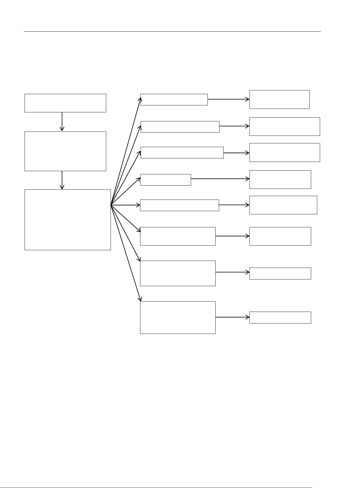
MCAC-VTSM-2015-02 R410A DC Inverter VRF V4 Plus Individual Series Side Discharge Type 50Hz
L1: low voltage protection
L4: MCE error
L2: high voltage protection
L8: frequency difference
in one second more than
15Hz
L9: frequency difference
between the real and the
than 15Hz
L0: module protection
L5: Zero speed protection
L7: Phase sequence
error
P6, L0~L9 error codes can’t
a time)
Check module and
compressor
Check power supply of
module
Check power supply of
module
Check module and
electric circuit
Check electric circuit
and compressor
Check module and
wiring connection
Check compressor
Check compressor
H4 will display if P6 occur
3 times in 30 minutes
Check whether inverter
DC generatrix is connected
connected inversely
4.15 P6/H4: Module protection
P6, L0~L9 error codes can’t display on digital tube automatically, these error codes will display on digital tube
only through SW3 button (pressure SW3 ten times, every one second for a time)
If the system display three times P6 protection in 60 minutes, the system will stop and display H4 error code.
When the system displays H4 error code, the system can resume only by restarting the machine. At this time,
malfunction should be disposed promptly to avoid further damage.
module is broken, and
eliminate the situation that
display on digital tube
automatically, these error
codes will display on digital
tube only through SW3
button (pressure SW3 ten
times, every one second for
setting frequency more
Troubleshooting 103
Page 27
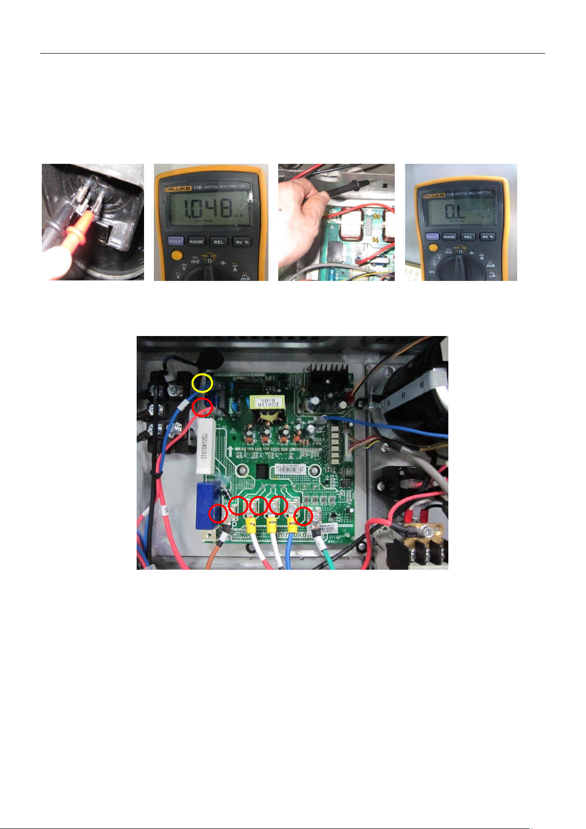
R410A DC Inverter VRF V4 Plus Individual Series Side Discharge Type 50Hz MCAC-VTSM-2015-02
N
3 2 4
5
1
P
1) L0 troubleshooting
Step 1: Compressor check
Measure the resistance between each two of U, V, W terminals of the compressor, all the resistance should be
the same and equal to 0.9~5 Ohms. (Fig. A and Fig. B)
Measure the resistance between each of U, V, W terminals of the compressor to ground (Fig. C), all the
resistance should trend to infinity (Fig. D), otherwise the compressor has been malfunction, needs to be
replaced.
Fig. A Fig.B Fig.C Fig.D
If the resistance value are normal, then go to step 2.
Step 2: Module check
1) DC voltage between terminal P and terminal N should be 1.41 times of the local power supply voltage.
2) DC voltage between terminal 1 and 2 should be 510V~580V.
3) Disconnect the terminal 3, 4, and 5 from inverter compressor. Measure the risistance between any two
terminals among terminal 1, 2, 3, 4, 5. All the values should be infinity. If any of the value approximates to 0,
the inverter module is damaged and should be replaced.
After replaced the inverter module, if the system is still abnormal, then go to step 3.
Step 3: DC generatrix check
Direction of the current in DC supply wire which is running through the inductor should be the same as the
direction of arrow marked on the inductor.
104 Troubleshooting
Page 28
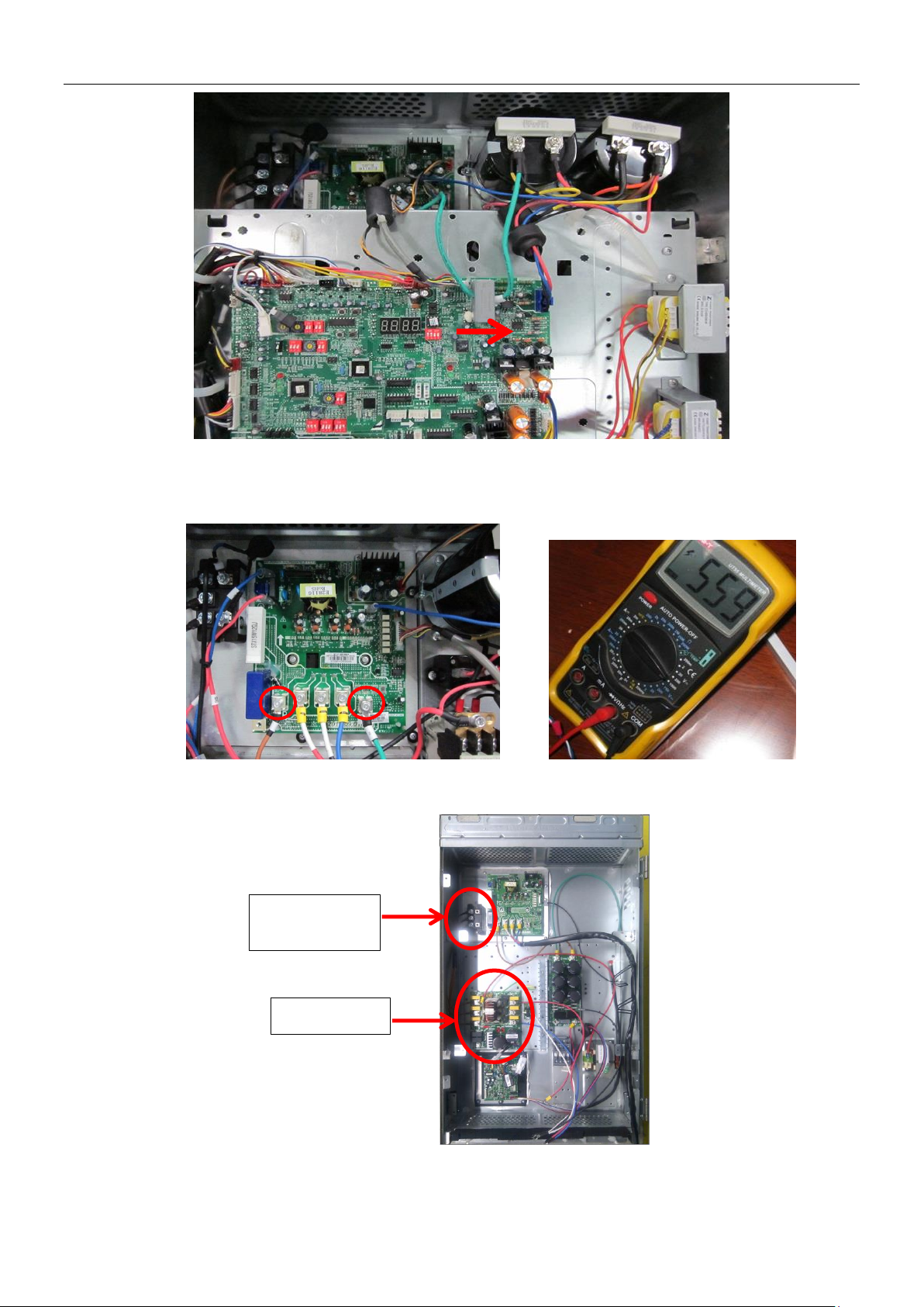
MCAC-VTSM-2015-02 R410A DC Inverter VRF V4 Plus Individual Series Side Discharge Type 50Hz
1
2
3-Phase bridge
rectifier
Filter board
2) L1/L4 troubleshooting
Step 1: Check the DC voltage between 1 and 2 terminal, the normal value should be 510V~580V, if the voltage
is lower than 510V, go to step 2.
Step 2: Check whether the wires of rectifier circuit are loose or not. If wires are loosen, fasten the wires. If wires
are OK, replace the main PCB.
3) L2 troubleshooting
Step 1: Check the DC voltage between 1 and 2 terminal, the normal value should be 510V~580V, if the voltage
Troubleshooting 105
Page 29
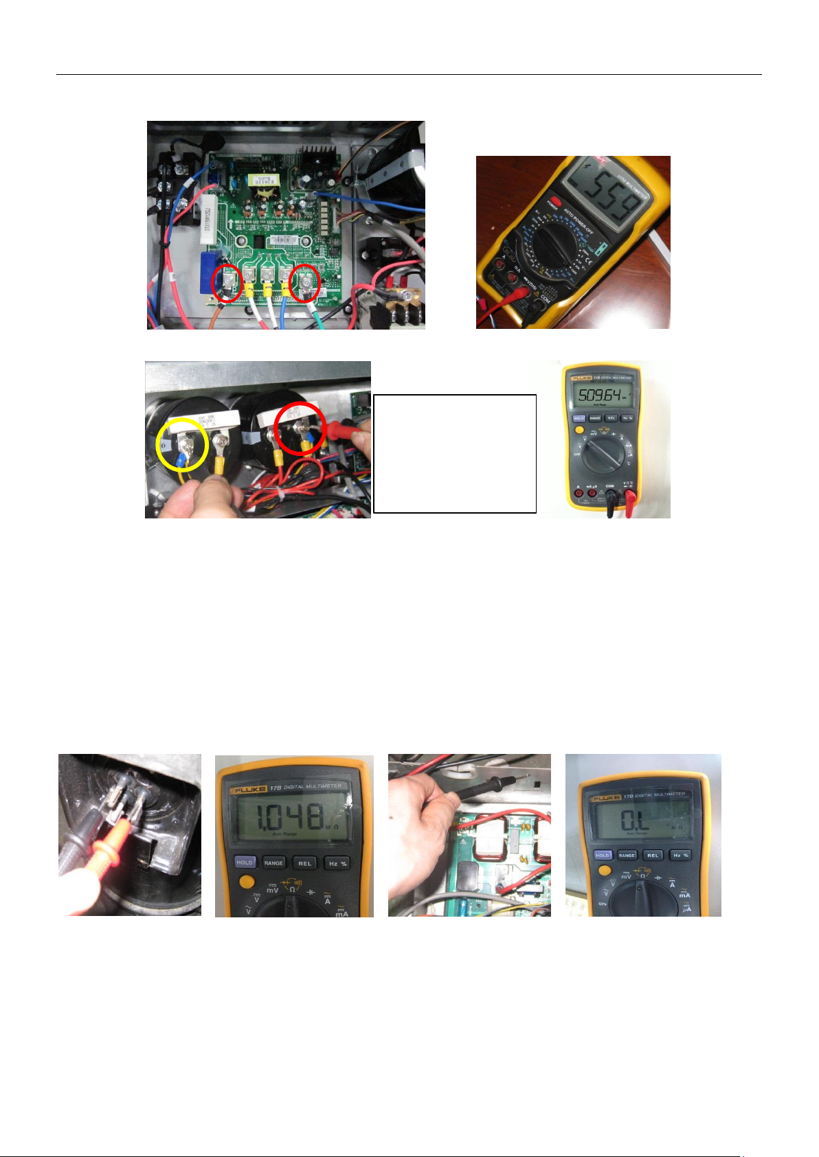
R410A DC Inverter VRF V4 Plus Individual Series Side Discharge Type 50Hz MCAC-VTSM-2015-02
Turn the measure
electrolytic capacitors
1
2
is higher than 580V, go to step 2.
Step 2: Check the voltage between the two electrolytic capacitors, the normal value should be 510V~580V.
range of the meter to
1kV, measure the
voltage between two
If the value is not in the range, that means the power supply for electrolytic capacitors has problem, you should
check the power supply, whether the voltage is too high and whether the voltage is stable.
If the voltage value is normal, then the main PCB has malfunction, it needs to be replaced.
4) L8/L9 troubleshooting
Step 1: Compressor check
Measure the resistance between each two of U, V, W terminals of the compressor, all the resistance should be
the same and equal to 0.9~5 Ohms. (Fig. A and Fig. B)
Measure the resistance between each of U, V, W terminals of the compressor to ground (Fig. C), all the
resistance should trend to infinity (Fig. D), otherwise the compressor has been malfunction, needs to be
replaced.
Fig. A Fig. B Fig. C Fig. D
If the resistance value are normal, then go to step 2.
Step 2: Disconncet the power wiring from the compressor(named compressor A) of the faulted system(named
system A).
If there is a system running normally nearby(named system B):
Extend the power line of the inverter compressor of system B, connect compressor A to the control box of
system B, make sure that the U, V, W terminals are connected in right order, then start system B.
106 Troubleshooting
Page 30
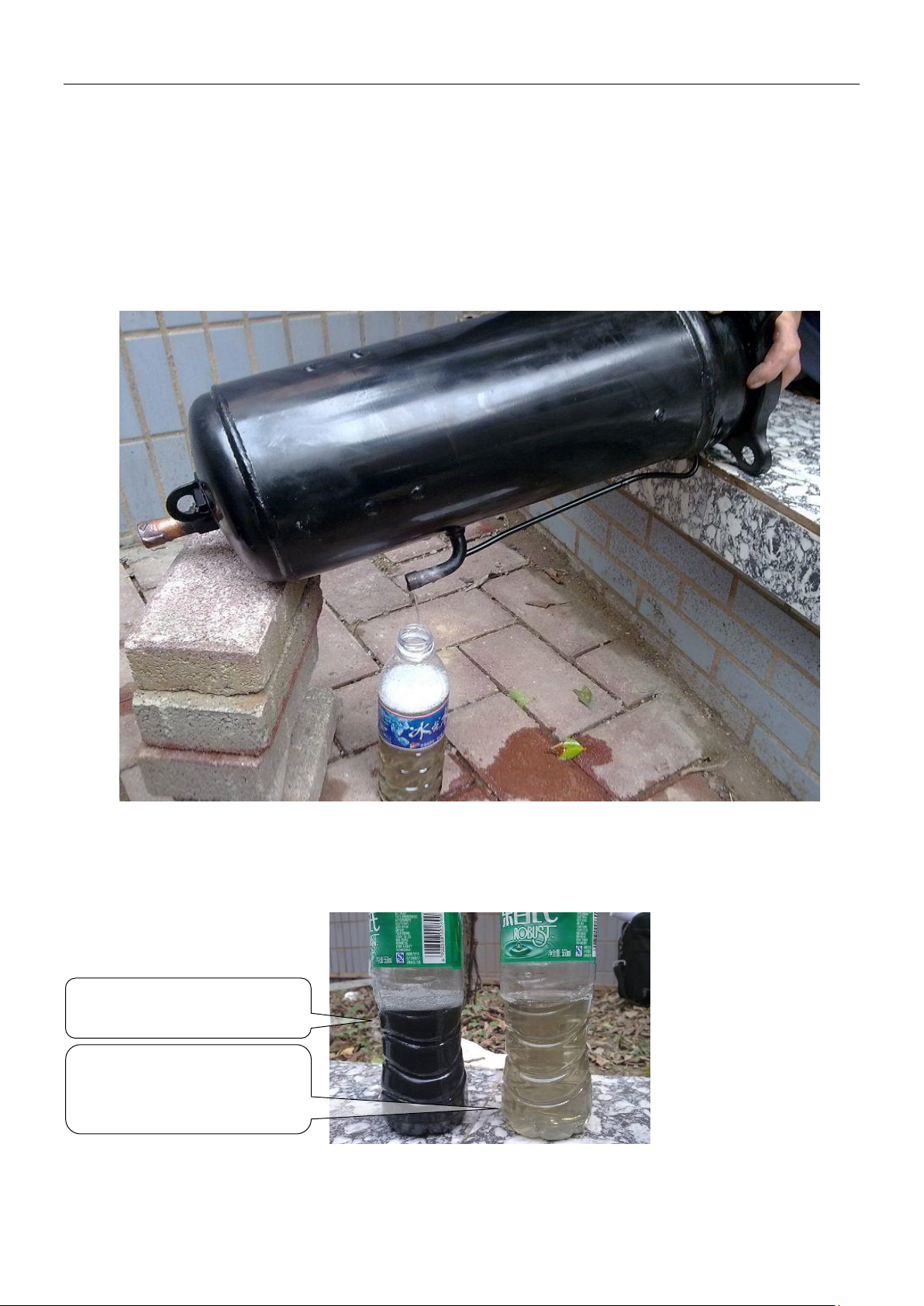
MCAC-VTSM-2015-02 R410A DC Inverter VRF V4 Plus Individual Series Side Discharge Type 50Hz
The oil is a little yellowing, but
quality is OK
The oil is black, it has been
carbonized
If compressor A can start normally, that means compressor is OK, the control box of system A is malfunction,
then raplace the main PCB of system A with correct wire connection.
If compressor A can not start normally, that means compressor A is demaged, needs to be replaced.
If there is no normal system nearby:
Replace the main PCB of system A with correct connection, if compressor A can start normally, it means the
main PCB which is replaced is damaged. If compressor A still can’t start normally, replace the compressor.
5) Guide for compressor replacement
Step 1: Take out the compressor from the faulty outdoor unit, pour out the oil from the compressor according to
the method illustrated. Normally the oil will outflow from the discharge pipe of the compressor.
Step 2: check the oil of the system
Normally the oil is clear and transparent, if it is a little yellowing, it is also OK. However, if the oil is become
black, feculent, or even there is impurity in the oil, that means the system has problems and the oil has gone
bad, the oil need to be replaced.
it is clear and transparent, the
Troubleshooting 107
Page 31
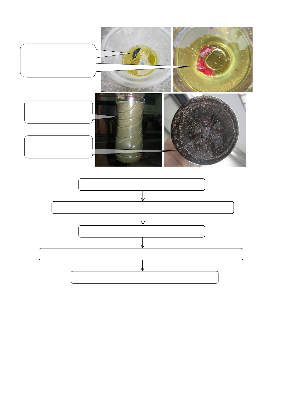
R410A DC Inverter VRF V4 Plus Individual Series Side Discharge Type 50Hz MCAC-VTSM-2015-02
The oil is still transparent,
The oil is still transparent, but
there is impunity in the oil, the
and gray
copper scrap
The compressor can’t be lubricated effectively.
The electric heat will rise and the temperature of the motor becomes increasingly high
The motor is burned and the compressor is damaged at last
The scroll plate, the crankshaft and the bearing of the compressor is worn
Abrasion leads to larger load, higher current
but there is impunity in the
oil, the impunity may clog
impunity may clog the filter
The oil becomes cloudy
The oil contains a lot of
If the oil has gone bad:
108 Troubleshooting
Page 32
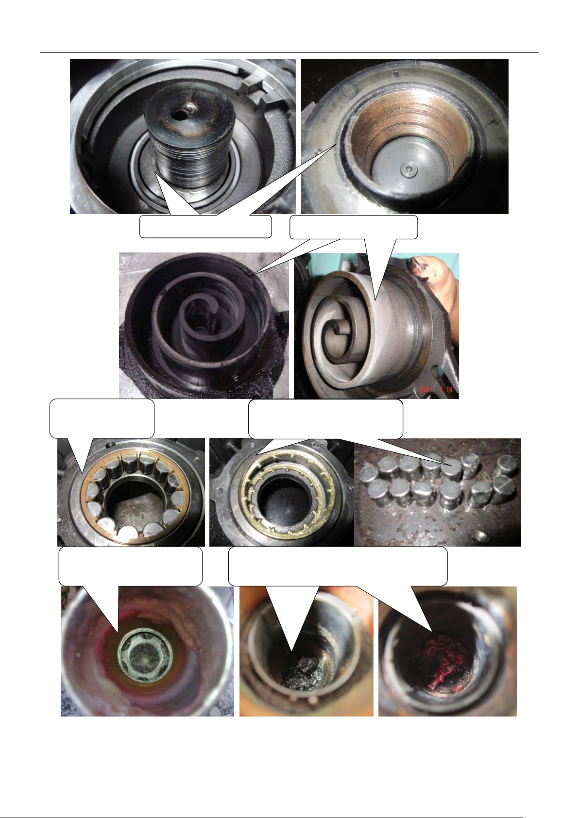
MCAC-VTSM-2015-02 R410A DC Inverter VRF V4 Plus Individual Series Side Discharge Type 50Hz
The crankshaft is
The scroll plate of the
The crankshaft is worn.
The scroll plate is worn.
A normal bearing
of the compressor
The bearing is worn seriously,
it is damaged completely
The bearing is worn seriously,
it is damaged completely
A clean filter (on the suction
pipe of the system)
The filter is blocked by impunity, the suction
and exhaust of the compressor will be
The filter is blocked by impunity, the suction
of the compressor will be abnormal
Troubleshooting 109
Page 33
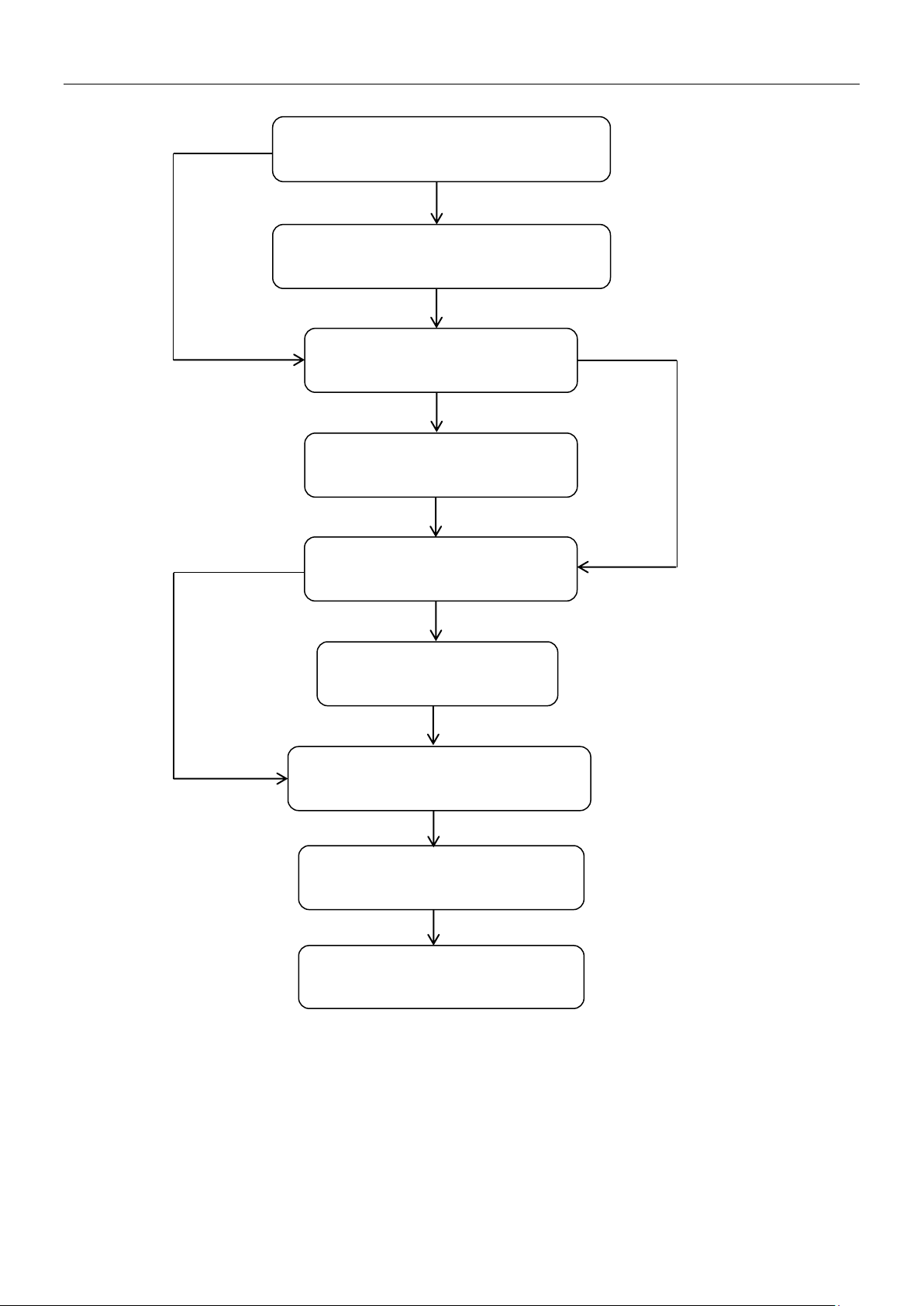
R410A DC Inverter VRF V4 Plus Individual Series Side Discharge Type 50Hz MCAC-VTSM-2015-02
Pour out all of the oil from the compressor,
oil separator and gas-liquid separator
The oil is dirty
Check the filter between the ball
valve and the 4-way valve
The filter is blocked by impunity
Clean the filter screen with
nitrogen, or replace the filter
Replace the compressor which
has been damaged
Add clean oil to the new compressor,
and gas-liquid separator
Replace the oil separator and
gas-liquid separator
Weld the pipes, vacuum drying the
system and recharge refrigerant
Make sure all the wire connection is
OK, restart the system
The oil is clean
The filter is clean
Pour out some oil from each compressor;
check the quality of the oil
The oil is dirty
The oil is clean
Step 3: Replace the compressor
Note:
1. Before pouring out the oil, shake the compressor, oil separator and gas-liquid separator first, because
impunity may deposit at the bottom of the tank.
2. If the oil of one compressor is clean, there’s no need to check the oil of the other compressor. If the oil of one
compressor has gone bad, check the oil of the other compressor is necessary. If all the oil of an outdoor unit
needs to be replaced, after adding oil to the compressors, the rest oil should be charged to the gas-liquid
separator.
110 Troubleshooting
Page 34
MCAC-VTSM-2015-02 R410A DC Inverter VRF V4 Plus Individual Series Side Discharge Type 50Hz
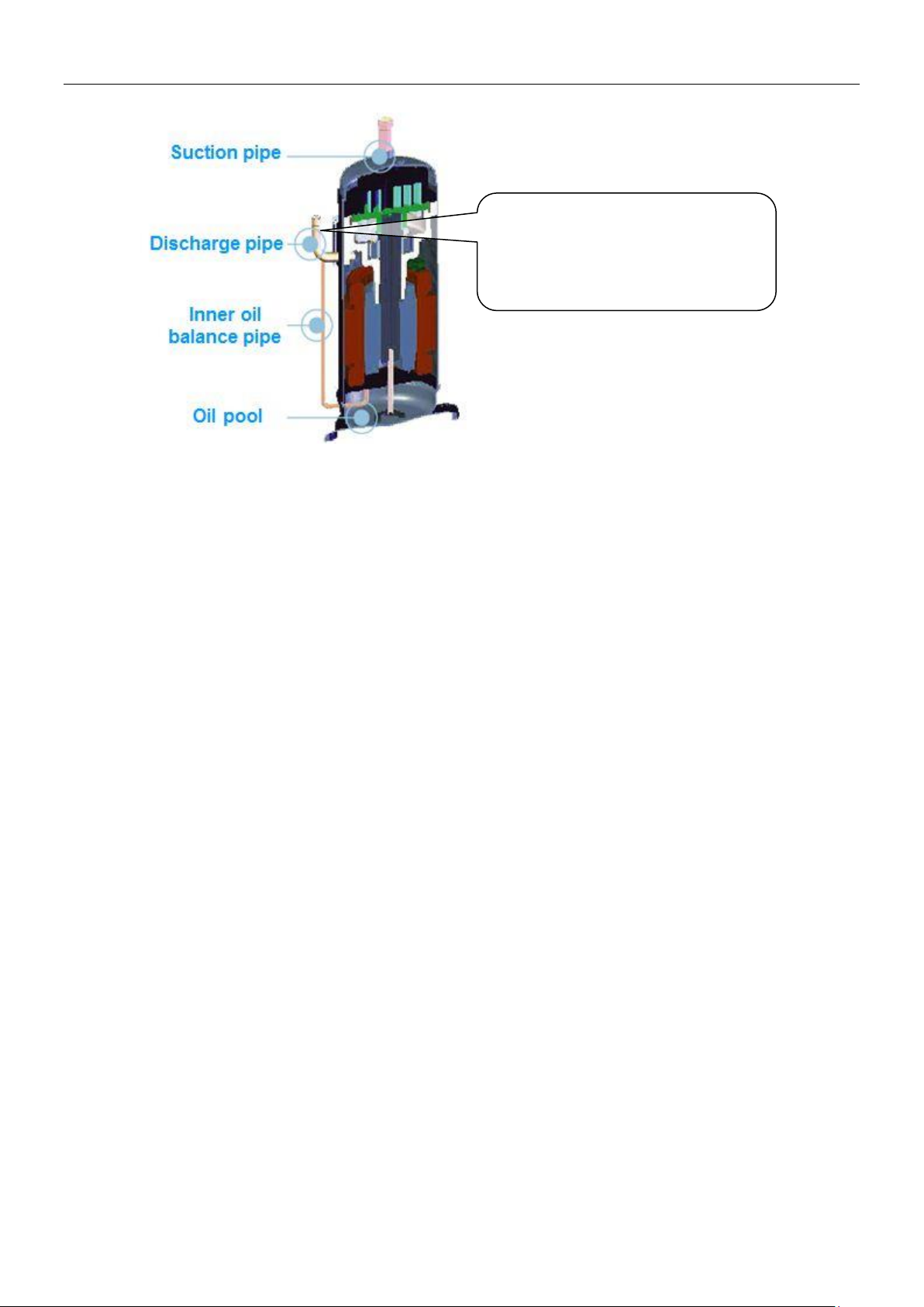
The discharge pipe is connected to
the oil pool of the compressor by the
inner oil balance pipe, add oil from
the discharge pipe with a funnel
3. Add oil to the compressor from the discharge pipe.
4. The type of the oil is FVC-68D, make sure the type of the oil is right because different compressor need
different type of oil, if the type is wrong there will be various kinds of problems.
Troubleshooting 111
Page 35
R410A DC Inverter VRF V4 Plus Individual Series Side Discharge Type 50Hz MCAC-VTSM-2015-02
Yes
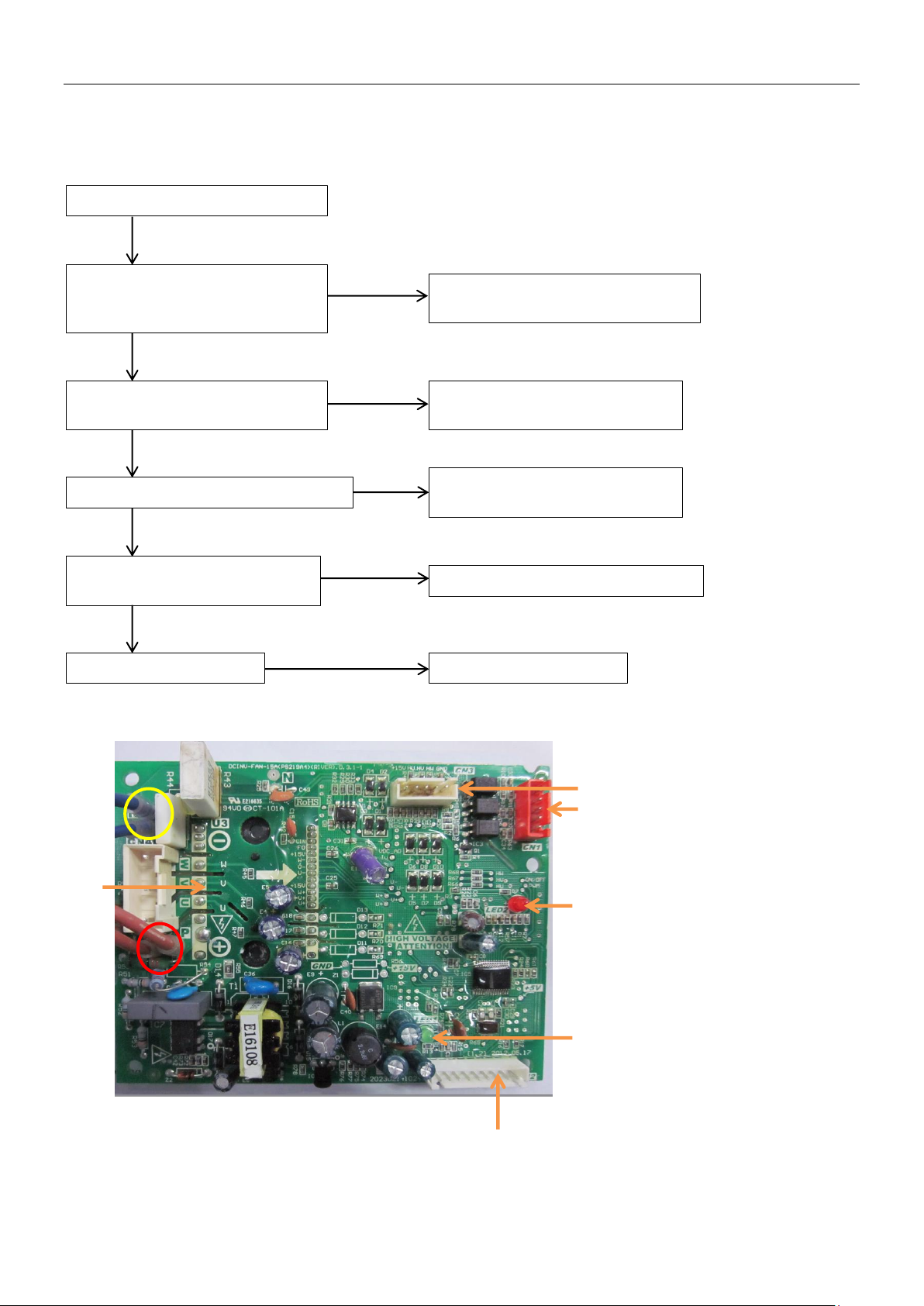
P9/H9: Fan module protection
The fan module is too hot for bad
temperature
Make sure the fan module working
in the normal temperature range
Some power wires or signal
wires of fan module are loose
Well connect the power wires
and signal wires
The fan motor is blocked or disabled
Clear away the block or replace
the fan motor
Output voltage between P and
N on fan module is abnormal*
Replace the power supply module
Fan module is disabled
Replace the fan module
No
No
No
No
Yes
Yes
Yes
Yes
1 Program input port
3 Fan motor U, V, W output port
5 PCB control signal input port
* The normal value of output
voltage between P and N on fan
5
6
4 3 2
1
P
N
4.16 P9/H9: DC fan module protection
If the system display three times P9 protection in 60 minutes, the system will stop and display H9 error code.
When the system displays H9 error code, the system can resume only by restarting the machine. At this time,
malfunction should be disposed promptly to avoid further damage.
heat dissipation or high ambient
Fan module instruction
2 Power supply indicator lamp
4 Fault indicator lamp
6 Signal feedback port
module is DC 310V
112 Troubleshooting
Page 36
MCAC-VTSM-2015-02 R410A DC Inverter VRF V4 Plus Individual Series Side Discharge Type 50Hz
Conditions
Fault indicator
lamp of fan
module
Power supply
indicator lamp
of fan module
Digital
tube
display
Malfunction analysis
Power on
Off
Off
Quantity
of IDU or
―0‖
Check the power supply circuit for fan module.
Check whether there has power supply for lightning
protection plate, whether the protective tube is broken,
whether the voltage after rectification is normal, whether the
bridge rectifier is broken.
Power on
Off
Flicker
Quantity
of IDU or
―0‖
Power supply of fan module has problem, needs to replace
the fan module.
When fan
motor start
At first the lamp
is on then the
lamp is off
On
P9/H9
Check whether the drive port and signal feedback port is
loose, whether the fan module and fan motor is installed
firmly. If above conditions are all OK, it needs to replace the
fan module.
When fan
motor start
At first the lamp
is on then the
lamp flicker
On
P9/H9
Check whether the transformer in lightning protection plate
Is open circuit, whether the relay is broken. If occurs above
problem, it needs to replace the lightning protection plate.
Fan motor
running
several
minutes
On
On
P9/H9
Check whether the capacity setting from dial switch is
accordance with actual ODU capacity, whether the capacity
from spot check is accordance with actual ODU capacity. If
occurs above problem, it needs to adjust the capacity setting.
If above conditions are both OK, it needs to replace the main
control board.
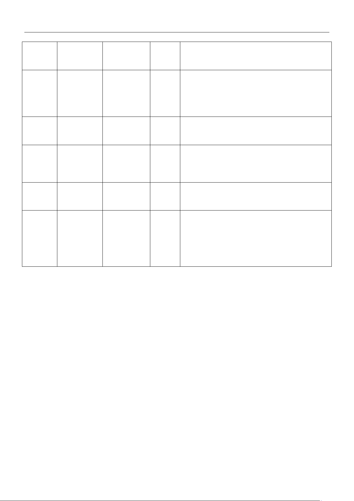
P9 protection analysis
Troubleshooting 113
Page 37
R410A DC Inverter VRF V4 Plus Individual Series Side Discharge Type 50Hz MCAC-VTSM-2015-02
The screw between inverter
module and radiating fin is
loose
Outdoor main PCB is damaged
Replace the outdoor
main PCB
PL/CL
Temperature sensor of main
or disabled①.
Replace the sensor
Yes
No
No
Yes
Tighten the screw,
make sure the
inverter module is
closed to the
radiating fin
Yes
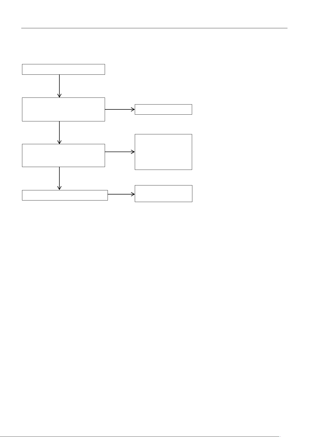
4.17 PL/C7: Temperature protection of main inverter module
When the temperature of inverter module is over 80oC, it will display PL protection.
If the system display three times PL protection in 100 minutes, the system will stop and display C7 error code.
When the system displays C7 error code, the system can resume only by restarting the machine.
inverter module is short circuit
1. How to check whether the temperature sensor is short circuit or disabled①:
Using a multi-meter to measure resistance, if the resistance is too small, the sensor is short circuit, if the resistance in certain
temperature is not consistent with attached table 2, the sensor is disabled
114 Troubleshooting
Page 38
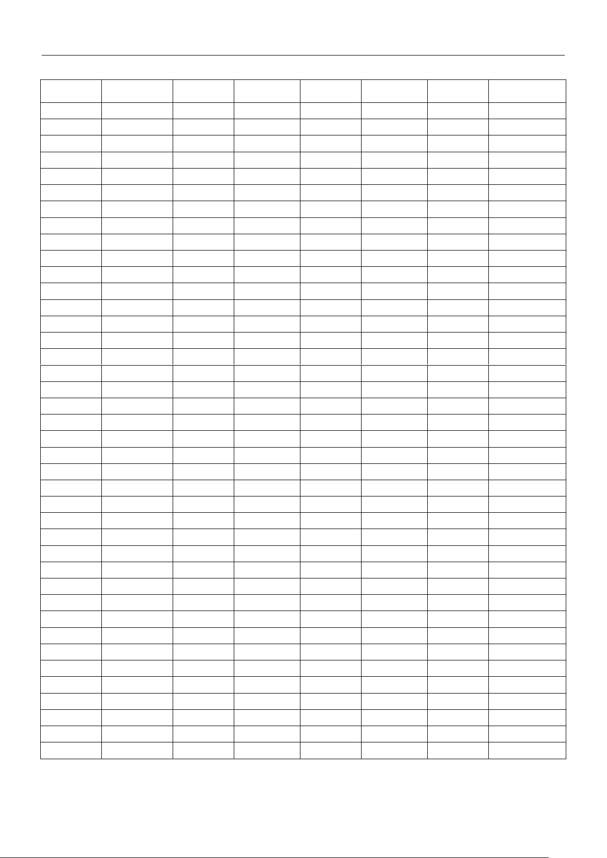
MCAC-VTSM-2015-02 R410A DC Inverter VRF V4 Plus Individual Series Side Discharge Type 50Hz
Temperature
(℃)
Resistance
value (kΩ)
Temperature
(℃)
Resistance
value (kΩ)
Temperature
(℃)
Resistance
value (kΩ)
Temperature
(℃)
Resistance
value (kΩ)
-20
115.266
20
12.6431
60
2.35774
100
0.62973
-19
108.146
21
12.0561
61
2.27249
101
0.61148
-18
101.517
22
11.5
62
2.19073
102
0.59386
-17
96.3423
23
10.9731
63
2.11241
103
0.57683
-16
89.5865
24
10.4736
64
2.03732
104
0.56038
-15
84.219
25
10
65
1.96532
105
0.54448
-14
79.311
26
9.55074
66
1.89627
106
0.52912
-13
74.536
27
9.12445
67
1.83003
107
0.51426
-12
70.1698
28
8.71983
68
1.76647
108
0.49989
-11
66.0898
29
8.33566
69
1.70547
109
0.486
-10
62.2756
30
7.97078
70
1.64691
110
0.47256
-9
58.7079
31
7.62411
71
1.59068
111
0.45957
-8
56.3694
32
7.29464
72
1.53668
112
0.44699
-7
52.2438
33
6.98142
73
1.48481
113
0.43482
-6
49.3161
34
6.68355
74
1.43498
114
0.42304
-5
46.5725
35
6.40021
75
1.38703
115
0.41164
-4
44
36
6.13059
76
1.34105
116
0.4006
-3
41.5878
37
5.87359
77
1.29078
117
0.38991
-2
39.8239
38
5.62961
78
1.25423
118
0.37956
-1
37.1988
39
5.39689
79
1.2133
119
0.36954
0
35.2024
40
5.17519
80
1.17393
120
0.35982
1
33.3269
41
4.96392
81
1.13604
121
0.35042
2
31.5635
42
4.76253
82
1.09958
122
0.3413
3
29.9058
43
4.5705
83
1.06448
123
0.33246
4
28.3459
44
4.38736
84
1.03069
124
0.3239
5
26.8778
45
4.21263
85
0.99815
125
0.31559
6
25.4954
46
4.04589
86
0.96681
126
0.30754
7
24.1932
47
3.88673
87
0.93662
127
0.29974
8
22.5662
48
3.73476
88
0.90753
128
0.29216
9
21.8094
49
3.58962
89
0.8795
129
0.28482
10
20.7184
50
3.45097
90
0.85248
130
0.2777
11
19.6891
51
3.31847
91
0.82643
131
0.27078
12
18.7177
52
3.19183
92
0.80132
132
0.26408
13
17.8005
53
3.07075
93
0.77709
133
0.25757
14
16.9341
54
2.95896
94
0.75373
134
0.25125
15
16.1156
55
2.84421
95
0.73119
135
0.24512
16
15.3418
56
2.73823
96
0.70944
136
0.23916
17
14.6181
57
2.63682
97
0.68844
137
0.23338
18
13.918
58
2.53973
98
0.66818
138
0.22776
19
13.2631
59
2.44677
99
0.64862
139
0.22231
Attached table 1: Resistance value of ambient temperature and pipe temperature sensor
Troubleshooting 115
Page 39
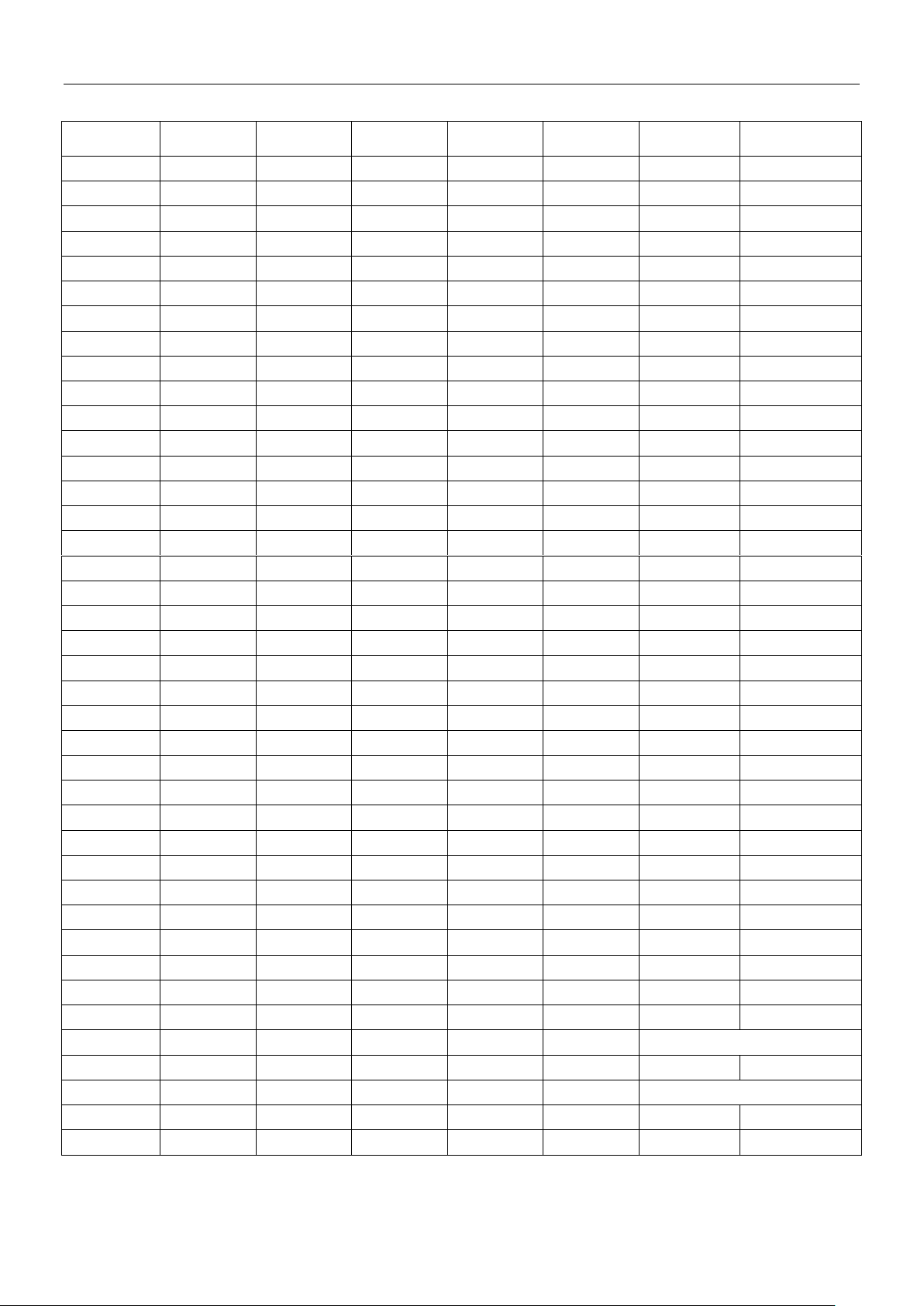
R410A DC Inverter VRF V4 Plus Individual Series Side Discharge Type 50Hz MCAC-VTSM-2015-02
Temperature
(℃)
Resistance
value (kΩ)
Temperature
(℃)
Resistance
value (kΩ)
Temperature
(℃)
Resistance
value (kΩ)
Temperature
(℃)
Resistance value
(kΩ)
-20
542.7
20
68.66
60
13.59
100
3.702
-19
511.9
21
65.62
61
13.11
101
3.595
-18
483
22
62.73
62
12.65
102
3.492
-17
455.9
23
59.98
63
12.21
103
3.392
-16
430.5
24
57.37
64
11.79
104
3.296
-15
406.7
25
54.89
65
11.38
105
3.203
-14
384.3
26
52.53
66
10.99
106
3.113
-13
363.3
27
50.28
67
10.61
107
3.025
-12
343.6
28
48.14
68
10.25
108
2.941
-11
325.1
29
46.11
69
9.902
109
2.86
-10
307.7
30
44.17
70
9.569
110
2.781
-9
291.3
31
42.33
71
9.248
111
2.704
-8
275.9
32
40.57
72
8.94
112
2.63
-7
261.4
33
38.89
73
8.643
113
2.559
-6
247.8
34
37.3
74
8.358
114
2.489
-5
234.9
35
35.78
75
8.084
115
2.422
-4
222.8
36
34.32
76
7.82
116
2.357
-3
211.4
37
32.94
77
7.566
117
2.294
-2
200.7
38
31.62
78
7.321
118
2.233
-1
190.5
39
30.36
79
7.086
119
2.174
0
180.9
40
29.15
80
6.859
120
2.117
1
171.9
41
28
81
6.641
121
2.061
2
163.3
42
26.9
82
6.43
122
2.007
3
155.2
43
25.86
83
6.228
123
1.955
4
147.6
44
24.85
84
6.033
124
1.905
5
140.4
45
23.89
85
5.844
125
1.856
6
133.5
46
22.89
86
5.663
126
1.808
7
127.1
47
22.1
87
5.488
127
1.762
8
121
48
21.26
88
5.32
128
1.717
9
115.2
49
20.46
89
5.157
129
1.674
10
109.8
50
19.69
90 5 130
1.632
11
104.6
51
18.96
91
4.849
12
99.69
52
18.26
92
4.703
13
95.05
53
17.58
93
4.562
14
90.66
54
16.94
94
4.426
15
86.49
55
16.32
95
4.294
B(25/50)=3950K
16
82.54
56
15.73
96
4.167
17
78.79
57
15.16
97
4.045
R(90℃)=5KΩ+-3%
18
75.24
58
14.62
98
3.927
19
71.86
59
14.09
99
3.812
Attached table 2: Resistance value of compressor discharge temperature sensor
116 Troubleshooting
Page 40
MCAC-VTSM-2015-02 R410A DC Inverter VRF V4 Plus Individual Series Side Discharge Type 50Hz
Ambient temperature (T4)
℃
20-27
27-33
33-38
38-45
Discharge pressure (spot check)
MPa
2.1-2.3
2.8-3.1
3.3-3.5
3.7-3.9
Pressure of high pressure valve
MPa
1.8-2.0
2.4-2.7
2.8-3.0
3.2-3.5
Pressure of low pressure valve
MPa
0.7-0.9
0.8-1.0
1.0-1.2
1.2-1.4
Discharge temperature (spot check)
℃
50-65
70-85
70-90
80-90
DC Inverter compressor current (spot check)
A
4-5
6-7
7-8
9-11
Fixed compressor current (spot check)
A
6-7
8-9
9-11
11-12
Average temperature of evaporator outlet T2B
℃
8-9
12-15
16-17
20
Ambient temperature (T4)
℃
-15--5
-5-5
5-12
12-18
Discharge pressure (spot check)
MPa
2.0-2.2
2.2-2.7
3.0-3.1
2.6-2.7
Pressure of high pressure valve
MPa
1.7-1.8
1.8-2.4
2.6-2.8
2.1-2.4
Pressure of low pressure valve
MPa
2.0-2.2
2.2-2.6
3.0-3.1
2.5-2.7
Discharge temperature (spot check)
℃
50-70
60-70
60-85
60-70
DC Inverter compressor current (spot check)
A 5 5-6
6-8
5-6
Fixed compressor current (spot check)
A 6 6-7
9-10
8-9
Average temperature of condenser outlet T2
℃
33
33-40
46-50
39-41
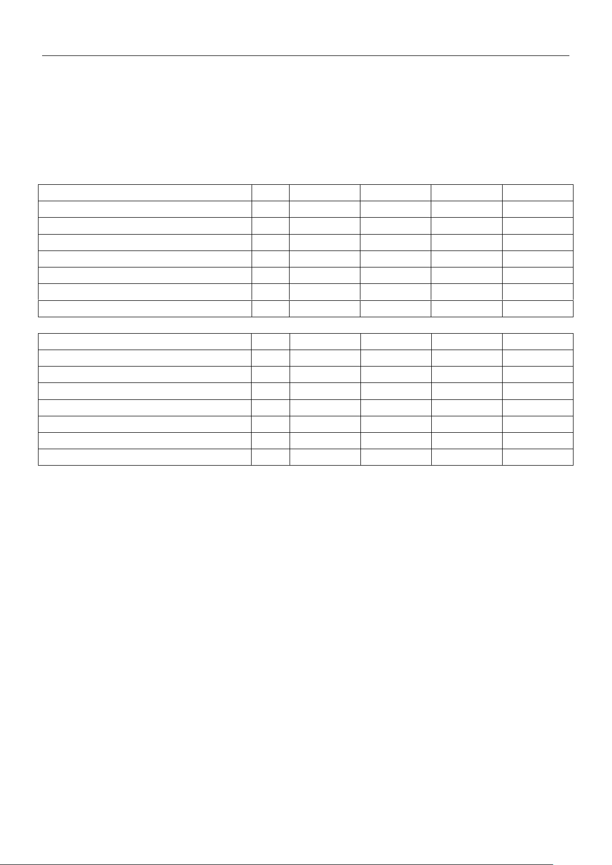
Attached table 3: Commissioning and operating parameters of refrigerant system
Conditions 1: Make sure outdoor unit can detect all the indoor units, the quantity of indoor units display steadily and be equal to
actual quantity of installed indoor units.
Conditions 2: Make sure all the valves in outdoor unit are open, indoor units EXV have connected to indoor PCB.
Conditions 3: The ratio of connectable indoor units is 100%. When ambient temperature is high, operate the system in cooling
mode and set the temperature 17℃. When ambient temperature is low, operate the system in heating mode and set the
temperature 30℃. Then get the parameters after system running normally more than 30 minutes.
Outdoor unit cooling parameters table
Outdoor unit heating parameters table
Troubleshooting 117
 Loading...