

Page 1
Congratulations on your purchase of an MDS engine. MDS engines are
noted for their excellent power, robust character, and efficient operation.
All MDS engines are designed to precise tolerances and should be handled
with care. The following information and recommendations are presented
to help you become more familiar with the assembly and operating
characteristics of your new MDS engine. For best results, please closely
follow the break-in procedures and adjustment suggestions. Also, be sure
to read the enclosed safety instructions and warranty information prior
to operation.
A. Assembly
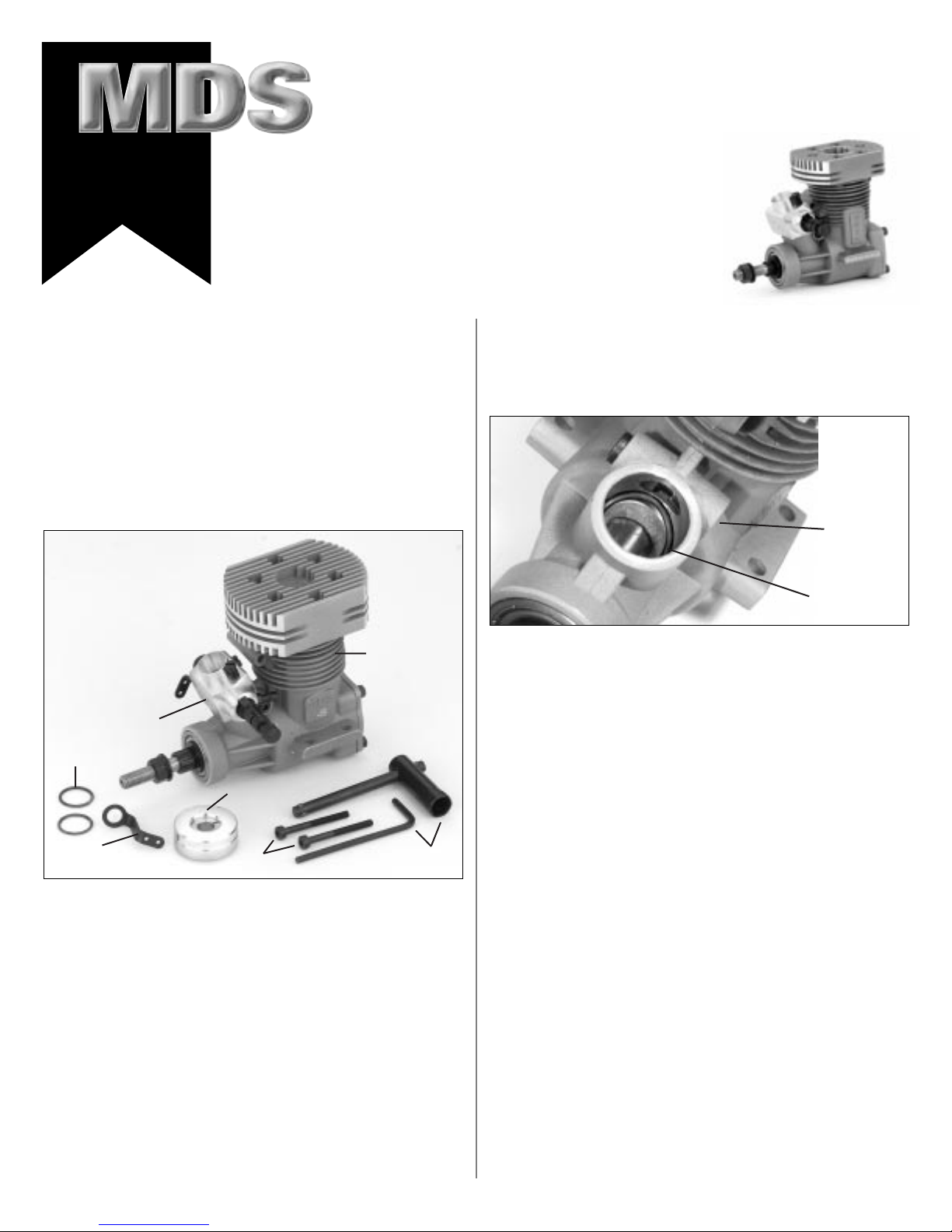
Inside the MDS engine box you should find one each of the
following items as shown in Photo 1:
To assemble your new engine, please follow these simple steps:
1. Remove the individual plastic bags from the box and place
them on a table or workbench in front of you. Remove the
engine from its plastic wrapper. Note: Some engines may
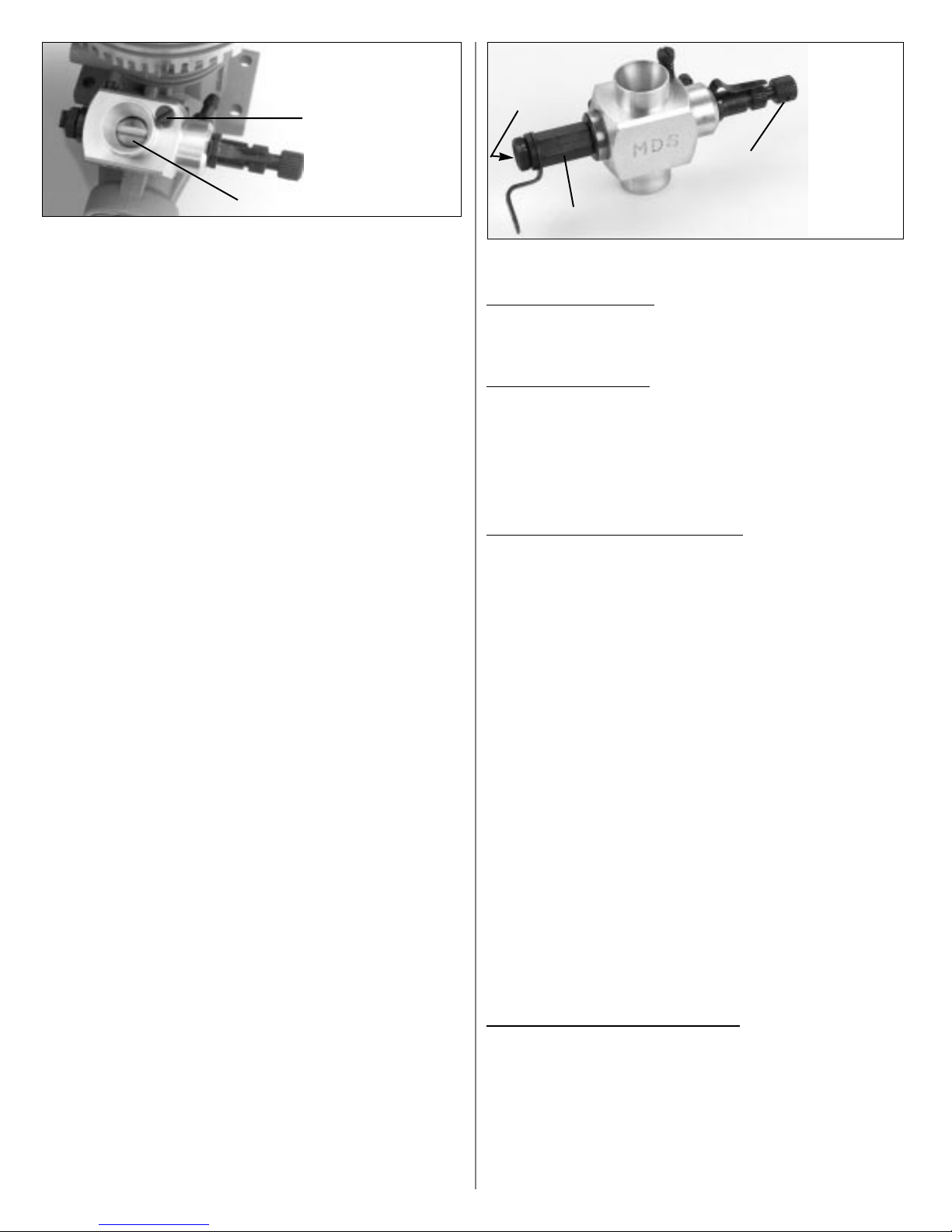
already have the carburetor installed. If so, it will be necessary to remove the carburetor at this time. If the carburetor
assembly does not remove easily, it may be necessary to
loosen the carburetor retaining bolt slightly (see Photo 2)
using the Allen wrench supplied in the parts/tool bag. Next,
rotate the carburetor back and forth slightly while pulling
upward to remove the carburetor.
2. Remove the two O-rings from the parts bag. Install the first
O-ring into the cavity of the air intake port of the crankcase,
as shown in Photo 2, making sure that the O-ring is seated
evenly at the bottom of the cavity and cannot come in
contact with the engine crankshaft. The second O-ring is a
spare.
3. It is now time to re-attach the carburetor to the engine.
Before inserting the carburetor, inspect the carburetor
retainer
to insure that the curved portion of the carburetor retainer
drawbar matches the inside wall of the air intake port. If it
does not, simply place it in position with your finger. Before
tightening the carburetor to the engine, it’s suggested that a
downward pressure be applied to the carburetor to create an
airtight seal to the O-ring. Align the carburetor so the needle
valve is 180 degrees to the crankshaft of the engine and
secure if using the provided Allen wrench.
Note: The carburetor is correctly positioned when the
throttle arm is located on the right side of the engine when
viewed from the rear.
CAUTION: Do not overtighten; doing so could damage the
carburetor body.
4. Move the carburetor barrel to its full idle position and adjust
the barrel stop screw so the air passage of the carburetor barrel is completely closed as shown in Photo 3 on the next
page. This will allow for the engine to be shut off by moving
the throttle trim of your transmitter to the full low position
during operation. Note: It’s important to do this procedure
at this time as the barrel stop screw is not accessible once the
engine is installed in the helicopter.
A. Engine assembly
B. Aeromix
™
carburetor
(may be pre-installed)
C. Complete accessory and
tool set (included tools
may vary slightly with
different engines)
D. Two muffler mounting
bolts (.38 & .48 only)
E. Tapered collet and
knurled prop washer
(.38 & .48 only)
F. Extended heli throttle arm
(.38 & .48 only)
G. Two carburetor O-Rings
• Instructions and
warranty card
Pro Heli Engine Operating Instructions
™
Photo 1
Photo 2
A
Carb
Retaining
Bolt
O-Ring
B
C
D
(.38 & .48 only)
E
(.38 & .48 only)
F
(.38 & .48 only)
G
Version 1.1
Page 2
5. In many helicopter installations, it will be necessary to
replace the existing throttle arm with the extended heli
throttle arm provided in the parts bag (.38 & .48 only). In
most cases, it’s suggested that the throttle arm be positioned
once the engine has been installed in the helicopter to
achieve proper alignment and to accomodate each engine
installation. Prior to attaching the throttle arm, it’s also
suggested that you first test fit the desired control linkage to
the throttle arm to insure that the attachment holes in the
throttle arm are of the correct size. In some cases, it may be
necessary to enlarge the attachment holes using a drill for
proper fit. Note: The holes are already enlarged in the .68
heli engine.
6. Attach the appropriate fan/flywheel assembly included with
your helicopter kit per the kit manufacturer’s instructions. A
tapered collet and knurled prop washer, as well as a stepped
spacer, have been included with this engine to facilitate
fan/flywheel assemblies which require this arrangement
(.38 & .48 engines only). If the tapered collet/knurled
prop washer are to be used, it will first be necessary to
remove the stepped spacer from the engine prior to attachement. Note: When attaching and tightening the fan/flywheel assembly to the engine, it’s suggested that a piston
locking tool be used to achieve proper tightness. We recommend the Revolution Piston Locking Tool (RVO1003) or similar item.
7. Install the engine into the helicopter per the kit manufacturer’s recommendations.
B. Understanding Your MDS Aeromix
™
Carburetor
The MDS Aeromix™carburetor is designed for use with the
Pro series of MDS helicopter engines. This carburetor provides
the proper air-fuel mixture necessary for helicopter flying and
provides smooth performance throughout the throttle operating range.
Note: If this is your first attempt at operating a model engine,
we suggest you seek the advice of an experienced modeler for
help, if possible. Your local hobby dealer may be able to help or
put you in contact with an experienced modeler who would be
willing to help you.
CAUTION: Before making any adjustments to the carburetor,
please consider the following: In helicopters, engine failure in
flight is a serious problem, especially for modelers who do not
have much flying experience. Such a failure will usually result
in loss of control of the helicopter and a resulting crash.
To ensure safe, reliable control of the helicopter in flight, you
must adjust the engine to achieve a throttle response that’s
quick and reliable. This means the carburetor adjustment is
very important for proper helicopter performance and must be
done with great care in order to obtain reliable throttle
response. Initial test flights are recommended at a very low
altitude (approximately 1 foot or less from the ground) until
reliable operation is achieved.
When the helicopter is in flight, accurate and reliable throttle
response in the medium speed hover range is very important!
This is because most initial helicopter flying (hovering) is done
at the medium speed position.
On this carburetor, there are two adjustable needle valves for
fuel flow control.
High Speed Needle V
alve
1. The High Speed Needle Valve (located on the left side of
carburetor as you look at the engine from the rear forward)
controls the mixture of the engine speed range from half
(midstick) to fully opened throttle.
Low Speed Needle V
alve
2. Low (idle) Speed Needle Valve (located in the throttle barrel
in right side with throttle arm) controls the mixture of
the engine speed range from idling to half open throttle
(midstick). Note: The idle needle valve is recessed into the
throttle arm extension on the .68 heli engines.
Note that the best mixture around half (midstick) throttle is
obtained by balancing the High Speed Needle Valve and the
Low Speed Needle Valve Settings.
Suggested Initial Needle V
alve Settings:
High Speed Needle Valve: 2-1/2 turns
Low Speed Needle Valve: 2-1/2 turns
Please note that all settings are established by turning the
respective needle valve clockwise until it stops, then backing
out counterclockwise to the desired position.
C. Engine Break-in
Your new MDS helicopter engine can be broken-in either in the
helicopter or on an engine test stand. Most helicopter pilots
choose to break-in their new engines while in the helicopter.
This is an acceptable practice, provided that the engine is run
in a low rpm condition, with a rich needle setting for a minimum of 6–8 tanks of fuel. Once this has been completed, the
engine can be leaned down in small increments and taken to
full power as needed. Note: If the engine is used in a lean or
full power condition during the first 6–8 flights, possible damage can occur, voiding the warranty.
D. Initial Test Flights and Adjustments
To start the engine, you will need the following items:
• We recommend a high quality, 2-cycle heli fuel
containing 15% to 30% nitromethane.
• Fuel pump
• Electric starter with appropriate extension
• Glow driver or power panel
• Glow plug (HAN3020 recommended)
• In-line fuel filter
The following adjustment procedures are recommended:
Initial Carburetor Adjustments
(Range from idle to 1/2 open throttle)
1. Start the engine with the transmitter throttle stick fully
down and the throttle trim lever set in the center position.
Be sure to hold the rotor blades firmly while starting in case
of clutch engagement.
2. Set the throttle trim lever so the engine runs with the highest idling rpm possible, without engaging the clutch. Let the
engine run for 1–2 minutes in this condition to warm up.
Photo 3
Carburetor barrel fully closed
Idle stop screw
Photo 4
Low Speed
Needle Valve
recessed inside
(.68 only)
High Speed
Needle Valve
Throttle Arm Extension
(.68 only)
Page 3

3. Pinch the fuel intake line between your fingers to restrict fuel
flow, while listening to the engine rpm. If the rpm increases
immediately, this may indicate that the low speed needle
valve is set too lean. Richen as necessary. Adjust the low
speed needle valve until a reliable idle is achieved and a hesitation of 2–3 seconds is established once the fuel line is
pinched.
4. Test hover the helicopter by advancing the transmitter throttle stick gradually until the helicopter just lifts up (floats)
from the ground. Warm up the engine while maintaining a
low level floating hover for approximately 10 seconds, then
slowly reduce the engine speed and allow the engine to idle
for a while. If the engine remains at a high idle for a few
seconds, then settles down (loses rpm), this may indicate
that the engine is running too lean. Adjust the low speed
needle valve in small 1/8 turn increments until the engine
will return to a low idle directly after hovering.
5. Repeat the above procedure several times. If the engine tends
to hesitate or cut-out as the throttle is increased, this may
indicate that the low (or high) speed needle valve is set too
rich. Lean the low speed needle valve slightly and re-test
until an acceptable throttle response is achieved. On the
contrary, if the low speed needle valve is set too lean, the
engine may hesitate longer and exhibit a weaker exhaust
tone. It may also be possible that the engine will run roughly
and produce a “missing” or inconsistent exhaust sound.
Richen the low speed needle valve as needed until the proper
adjustment is achieved.
6. If the engine runs with hesitation but does not stop, try to
hover the helicopter, maintaining an altitude of approximately 1 foot from the ground and carefully watching the
exhaust smoke. If the mixture is too rich, you may observe
an excess of exhaust smoke and the throttle response will be
very soft. If the mixture is too lean, the engine will run with
a higher pitched exhaust sound, lose power gradually, and
little smoke will be produced, showing an overheating tendency. It will be difficult to maintain a hover or keep the
helicopter flying. CAUTION: Do not continue to fly the
helicopter in this condition as this could cause severe damage to your engine. Re-adjust the fuel mixture as needed.
Note: In most cases, the higher the nitro content of the fuel,
the more the engine will smoke due to increased oil content
in the fuel.
Maximizing High Speed Performance
This setting will depend on the individual characteristics of the
helicopter engine/muffler configuration, the fuel used, and the
atmospheric conditions. The high speed needle valve should be
gradually closed (leaned out) in 1/8 turn increments until the
highest performance is obtained in flight at full power.
CAUTION: Do not close the high speed needle valve to a lean
setting and risk overheating the engine during the first 6–8
tankfuls of operation during the initial break-in process.
Operating the engine at too lean a setting in pursuit of maximum performance is not recommended and can cause damage
to the engine. Note: Do not attempt these adjustments until a
reliable fuel mixture setting in the initial hovering position has
been achieved. If you are not proficient in forward flight, seek
the help of a more experienced pilot for these adjustments.
Maximizing Middle Range of Performance
(Hovering speed)
In helicopter flight, throttle response at hovering speeds is very
important. If the low speed needle valve and high speed needle
valve are properly adjusted (balanced) the mixture will be correct through the middle range of performance. If, however,
minor re-adjustments are necessary for the best possible throttle
response, use the following symptoms to make the necessary
corrections:
1. If the mixture at the middle range of operation is too lean,
gradually increased engine speed is accompanied by diminished exhaust smoke and a high-pitched exhaust sound
while maintaining a hover. In some extreme cases, the
engine will overheat and begin to lose power to a point
where a hover cannot be maintained. In this situation, open
both the high speed and low speed needles valve 1/8 turn
counterclockwise (richer) and retest.
2. If the mixture at middle range of operation is too rich, positive and quick throttle response will not be possible to
obtain. Exhaust smoke will be dense, and the exhaust sound
will be lower, accompanied sometimes by a considerably
reduced rotor speed. When this occurs, close both the high
speed and low speed needle valves clockwise (leaner) 1/8 of a
turn and re-test.
Note: Make any needle valve adjustments in small increments
of not more than 1/8 of a turn when trying to make adjustments to the middle range of operation. Excessive re-adjustment will upset either the low or high speed performance. Be
patient when making re-adjustments so you can find the best
balance of idle, hover and high speed performance. You want
the engine to respond quickly and positively to the throttle
control. Throttle response at hovering speeds is also affected by
the relationship of the main rotor pitch curves and engine
throttle curves. If the optimum middle range throttle response
cannot be obtained using the carburetor adjustments described
above, try adjusting the helicopter’s pitch and throttle curves to
achieve the desired response.
E. Engine Care
D
os
Fuel
Always use clean, fresh fuel. Because dirt is the number one
enemy of any engine, we highly recommend the use of an
in-line fuel filter between the tank and the carburetor. Also,
place one between your fuel pump and the tank filler line.
After-Run Oil
Because model fuel contains methanol, it has the property of
drawing moisture from the atmosphere. Exposure to moisture
can cause corrosion to such vital engine parts as the bearings
and crankshaft. Therefore, we strongly urge that after every
flying session you drain all fuel from the tank and then put
approximately 1 oz. of after-run fuel into the fuel tank. We
recommend Hangar 9 Final Run (HAN3100). Start the engine
and let it run for 1–2 minutes at idle. Drain the excess after-run
fuel from the tank. Your engine will now be protected against
corrosion.
Glow Plug
Proper glow plug selection is extremely important if you are to
achieve maximum performance from your MDS heli engine.
We recommend the use of the Hangar 9 #3 heli performance
plug (HAN3020).
Inspection
Periodically remove the muffler and inspect the piston
through the exhaust port. Any signs of scoring may be an
indication that the engine has been overheated and run in a
lean condition.
Don’ts
Don’t dismantle the engine unnecessarily as doing so can
cause damage to the precision fit parts, such as the piston and
sleeve. If it’s necessary to clean the interior of the engine (such
as after a crash), remove only the muffler, carburetor, cylinder
head and backplate. You should be able to clean all foreign
matter from the engine without disturbing the fit of the precision parts. Any further disassembly could result in voiding the
manufacturer’s warranty.
F. MDS Safety Instructions and Warnings
See the enclosed safety instruction card for details.
G. Service and Warranty
See the enclosed registration card for details.
Page 4

MDSMAN4 Version 1.1
8
5
6
18
4
3
2
1
16
7
19
15
9
10
11
12
13
14
15
17
11
1
2
3
4
5
6
7
8
9
10
11
28
12
No. Description .38FSH Pro .48FSH Pro .68FSH Pro
1 High Speed Needle Valve Assembly 04600250 04600250 04600250
2 Idle Stop Screw & Spring 04600240 04600240 04600240
3 Carburetor Body 03800201 03800201 04600201
4 Fuel Inlet Nipple & Gasket 04000230 04000230 04000230
5 Throttle Barrel Retaining Screw 04600212 04600212 04600212
6 Throttle Barrel Spring 04000211 04000211 04000211
7 Throttle Barrel 04000210 04000210 06100210
8 Low Speed Needle Valve 04600215 04600215 04600215
9 Throttle Lever Arm 04000220 04000220 —
10 Throttle Lever Arm Extended (Heli) 03830220 03830220 03830220
11 Throttle Lever Nut & Washer 04000221 04000221 03830221
12 Throttle Arm Extension — — 06830225
28 Carburetor O-Ring 03800092 03800092 06800092
No. Description .38FSH .48FSH Pro .68FSH Pro
1 Prop Nut & Washer 03830002 03830002 06800002
2 Top Hat/Sleeve/Stepped Spacer 03830008 04830008 N/A
3 Prop Washer/Tapered Collet 03830006 04830006 06800006
4 Front Ball Bearings 03800021 03800021 06800021
5 Rear Ball Bearing 04000022 04600022 06800022
6 Crankcase 03800060 04830060 06800060
7 Crankshaft 03830030 04830030 06830030
8 Backplate 03800061 04001061 06800061
9 Connecting Rod 03800031 04800031 06800031
10 Wrist Pin 03800033 04800033 06800033
11 Wrist Pin Clips 03800034 06800034 06800034
12 Piston & Cylinder Assembly 03800040 04800040 06830040
13 Head Gasket 03800053 04800053 06800053
14 Cylinder Head 03830050 04830050 06830050
15 Screw Set 02800091 04001091 06800091
16 Muffler Screw Set 03800304 04600304 06800304
17 Carburetor Retainer & Nut 04600090 04600090 04600090
18 F/R Gasket 03800062 04600062 06800062
19 Carburetor 03800200 03800200 06830500
Aeromix™Carburetor Parts Diagram
Dimensions (mm) A B C D E F G
MDSE03830 .38 Heli 30 39 15 37 77 65 1/4 x 28
MDSE04830 .48 Heli 36 44 17.5 55 87 100 1/4 x 28
MDSE06830 .68 Heli 40 52 24 55 100 120 5/16 x 24
Engine Parts Diagram
B
A
C
D
E
F
G
=HEIGHT
=LENGTH
=CRANKSHAFT
 Loading...