

Page 1

TM
MX-2100/2104
Data, Voice, Fax and LAN Integrating
Modular Multiplexer
Installation and Operation Manual
NOTICE
This manual contains information that is proprietary to MICROWAVE DATA SYSTEMS, INC.
No part of this publication may be reproduced in any form whatsoever without prior written
approval by MICROWAVE DATA SYSTEMS, INC.
No representation or warranties for fitness for any purpose other than what is specifically
mentioned in this manual is made either by MICROWAVE DATA SYSTEMS, INC. or its
agents.
MICROWAVE DATA SYSTEMS, INC. reserves the right to revise this publication and make
changes without obligation to notify any person of such revisions or changes.
For further information contact MICROWAVE DATA SYSTEMS, INC. at the address below or
contact your local distributor.
MICROWAVE DATA SYSTEMS, INC.
175 SCIENCE PARKWAY
ROCHESTER, NY 14620-4261 U.S.A.
Tel: General Business: +1 (716) 242-9600
Customer Service: +1 (800) 474-0964
Fax All Services: +1 (716) 242-9620
Internet E-mail: techsupport@microwavedata.com
World Wide Web: http://www. microwavedata.com
2002 Microwave Data Systems, Inc. Pub. No. 8011130000
Page 2

Page 3

SAFETY WARNINGS
Always observe standard safety precautions during installation, operation and maintenance of this
product. Only qualified and authorized service personnel should carry out adjustment,
maintenance or repairs to this instrument. No adjustment, maintenance or repairs should be
performed by either the operator or the user.
WARRANTY FOR PRODUCTS MANUFACTURED BY
MICROWAVE DATA SYSTEMS, INC.
A. MICROWAVE DATA SYSTEMS, INC. (MDS) products, except as stated otherwise in an
applicable price list, are warranted against defects in workmanship and material for a period
of one (1) year from date of delivery as evidenced by MDS's packing slip or other
transportation receipt.
B. MDS’s sole responsibility under this warranty shall be to either repair or replace, at its
option, any component which fails during the applicable warranty period because of a defect
in workmanship and material, provided PURCHASER has promptly reported same to MDS
in writing. All replaced Products or parts shall become MDS's property.
C. MDS will honor the warranty at MDS's repair facility in Rochester, New York. It is
PURCHASER's responsibility to return, at its expense, the allegedly defective Product to
MDS. PURCHASER must obtain a Return Material Authorization (RMA) number and
shipping instructions from MDS prior to returning any Product under warranty.
Transportation charges for the return of the Product to PURCHASER shall be paid by MDS
within the United States. For all other locations, the warranty excludes all costs of shipping,
customs clearance and other related charges. If MDS determines that the Product is not
defective within the terms of this warranty, PURCHASER shall pay MDS all costs of
handling, transportation and repairs at the then prevailing repair rates.
D. All the above warranties are contingent upon proper use of the Product. These warranties
will not apply (i) if adjustment, repair or parts replacement is required because of accident,
unusual physical, electrical or electromagnetic stress, neglect, misuse, failure of electric
power, environmental controls, transportation, not maintained in accordance with MDS
specifications, or abuses other than ordinary use; (ii) if the Product has been modified by
PURCHASER or has been repaired or altered outside MDS's repair facility, unless MDS
specifically authorizes such repairs or alterations; (iii) where MDS serial numbers, warranty
data or quality assurance decals have been removed or altered.
E. MDS also reserves the right to make product improvements without incurring any obligation
or liability to make the same changes in Products previously manufactured or purchased. In
no event shall MDS be liable for any breach of warranty in an amount exceeding the net
selling price of any defective Product. No person, including any dealer, agent or
representative of MDS is authorized to assume for MDS any other liability on its behalf
except as set forth herein. Non-payment of any invoice rendered within the stated payment
terms automatically cancels any warranty or guarantee stated or implied. If any payment is
due MDS for services performed hereunder, it shall be subject to the same payment terms as
the original purchase.
F. EXCEPT FOR THE EXPRESS WARRANTIES STATED HEREIN, MDS DISCLAIMS
ALL WARRANTIES ON PRODUCTS FURNISHED HEREUNDER, INCLUDING,
WITHOUT LIMITATION, ALL IMPLIED WARRANTIES OF MERCHANTABILITY
AND FITNESS; and the stated express warranties are in lieu of all obligations or liabilities
on the part of MDS arising out of or in connection with the performance of the Products.
Page 4

WARRANTY FOR PRODUCTS MANUFACTURED BY OTHERS
A. For products not manufactured by MDS, the original manufacturer's warranty shall be
assigned to PURCHASER to the extent permitted and is in lieu of any other warranty,
expressed or implied.
B. For warranty information on a specific product, a written request should be made to MDS.
FCC-15 User Information
This equipment has been tested and found to comply with the limits of the Class A digital device,
pursuant to Part 15 of the FCC rules. These limits are designed to provide reasonable protection
against harmful interference when the equipment is operated in a commercial environment. This
equipment generates, uses and can radiate radio frequency energy and, if not installed and used in
accordance with the instruction manual, may cause harmful interference to the radio
communications. Operation of this equipment in a residential area is likely to cause harmful
interference in which case the user will be required to correct the interference at his own expense.
Page 5

Foreword
This manual describes the MX-2100/2104 family of data, voice, fax and
LAN integrating modular multiplexers. The manual covers the general
system characteristics, presents typical system applications, and provides
installation, operating procedure and configuration information for the
modules that are part of the basic MX-2100/2104 system configuration.
This release of the manual covers the characteristics of equipment
equipped with the Common Logic Module running software version 3.1
and above.
Manual Organization
This manual is organized as follows:
Chapter 1. General Information
presents the main features and typical applications of the MX-2100/2104
family, describes the various equipment versions, and lists the technical
characteristics of the MX-2100/2104 systems.
Preface
Chapter 2. Installation
provides detailed installation and operation instructions for MX-2100/2104
systems.
Chapter 3. Configuring MX-2100
provides general instructions for using and managing MX-2100/2104
systems by means of terminals and Telnet hosts.
Chapter 4. Operation
provides typical configuration procedures for MX-2100/2104 systems.
Chapter 5. Diagnostics
describes the diagnostic and performance monitoring functions supported
by MX-2100/2104 systems.
Appendix A. Connection Data
provides connection data for the basic modules used in the MX-2100/2104
system.
Appendix B. Alarms
explains the alarms and configuration error messages generated by the
MX-2100/2104 system.
Page 6

Appendix C. SNMP Management
describes the SNMP and IP environments, and provides background
information regarding the handling of management traffic.
Appendix D. Software Download
provides instructions for the installation of new software releases.
Appendix E. Configuration Parameters
lists the various parameters that can be used to configure MX-2100/2104.
Appendix F. Command Set Description
describes MX-2100/2104 commands.
Conventions
Note
Caution
A note draws attention to a general rule for a procedure, or to exceptions to
a rule.
A caution warns of possible damage to the equipment if a procedure is not
followed correctly.
A warning alerts to the presence of important operating and maintenance
(servicing) instructions in the literature accompanying the equipment. If
Warning
these instructions are not followed exactly, bodily injury may occur.
Related Documentation
In addition to this system manual, separate Installation and Operation
Manuals are available for each of the modules that are used in the
MX-2100/2104 systems. Each module’s Installation and Operation Manual
presents the technical characteristics, applications and specific
configuration information for that module.
Note that when the module manual refers to the respective MX-2000 or
MX-2004 system Installation and Operation Manual, refer to the
corresponding section of
this
system manual.
Page 7

Quick Start Guide
This Quick Start Guide is a brief step by step guide to setting up and using your
MX-2100. It is a supplement to the MX-2100/2104 Installation and Operation
Manual.
1. Installing MX-2100
To install MX-2100 (for more detailed instructions refer to the System Installation
and Setup chapter):
1. Unpack the equipment.
2. Check that your site conforms to the equipment requirements (refer to Site
Requirements in the System Installation and Setup chapter).
3. Check the power supply rating considerations (refer to Power Supply Rating
Considerations in the System Installation and Setup chapter).
4. Install the MX-2100 enclosure (refer to Installation and Setup in the System
Installation and Setup chapter).
5. Install an additional KPS module if necessary (refer to Installation and Setup in
the System Installation and Setup chapter).
6. Install the KM-Ringer module (refer to Installation and Setup in the System
Installation and Setup chapter).
7. Connect the power cable, the KM-Ringer module, the Supervisory Port (KCL.2
module), the KML module, option modules and I/O modules (refer to
Interfaces and Connections in the System Installation and Setup chapter).
8. Set the IP address using the DEF AGENT (refer to DEF AGENT in the Command
Set Description appendix).
2. Operating MX-2100
To operate MX-2100 (for more detailed instructions refer to Operating Instructions
in the Operation chapter):
1. If MX-2100 includes a KM-Ringer module, set the KM-Ringer module power
switch to OFF.
2. Turn on MX-2100 by setting the ON/OFF switches (on the rear panels) to ON.
3. Check the front-panel indications (refer to Operating Instructions in the
Operation chapter).
Operating MX-2100 1
Page 8

Quick Start Guide MX-2100/2104 Installation and Operation Manual
4. If MX-2100 includes a KM-Ringer module, turn it on by setting its POWER
switch to ON. Verify that the RING VOLTAGE and BATTERY VOLTAGE
indicators light.
5. Check the MX-2100 configuration (refer to Checking Current Operating
Configuration in the Operation chapter).
6. Check the normal MX-2100 operating indications (refer to Normal Indications
in the Operation chapter).
7. MX-2100 has diagnostic functions which can be used to test the proper
operation of the MX-2100 system and identify the faulty components. For an
explanation of the MX-2100 diagnostic functions refer to the Diagnostics
chapter.
8. Turn off MX-2100 as follows:
- If MX-2100 includes a KM-Ringer module, then turn off the
KM-Ringer before MX-2100.
- For the MX-2100’s KPS modules and MX-2104,
set the ON/OFF switches (on the rear panels) to OFF.
3. Setting-Up the Local Configuration
To set-up the MX-2100 local configuration (for more detailed information refer to
Setting Configuration Parameters in the Configuring MX-2100 chapter):
1. Set the system parameters refer to Configuring the System Parameters in the
Configuring MX-2100 chapter).
2. Select the main link parameters (refer to Configuring the Main Link Parameters
in the Configuring MX-2100 chapter).
3. Select the channel parameters (refer to Configuring the Channel Parameters in
the Configuring MX-2100 chapter).
4. Controlling MX-2100 from a Supervisory Port
To control MX-2100 from a supervisory port (for more detailed instructions refer to
Operating Instructions in the Operation chapter):
1. Start a session for MX-2100 (refer to Starting a Session - Single MX-2100 and
Starting a Session - Multiple MX-2100 in the Operation chapter).
2. Type the desired commands after the working prompt and press Enter to
execute the command. Refer to the Command Set Description appendix for a
list of commands available.
3. End the control session by typing EXIT. You can now control MX-2100 from
the front panel (refer to General Front Panel Operating Instructions in the
Configuring MX-2100 chapter).
2 Controlling MX-2100 from a Supervisory Port
Page 9

Contents
Chapter 1 General Information
UNCTIONAL DESCRIPTION
1.1 F
Main System Features ..............................................................................................1-1
System Supervision and Configuration......................................................................1-4
Diagnostic Capabilities.............................................................................................1-6
HYSICAL DESCRIPTION
1.2 P
MX-2100, General Description ................................................................................1-6
MX-2100 Rear Panel................................................................................................1-7
MX-2100 Front Panel...............................................................................................1-8
MX-2104, General Description ................................................................................1-8
MX-2104 Rear Panel................................................................................................1-9
MX-2104 Front Panel.............................................................................................1-10
Common Logic Modules........................................................................................1-10
Main Link Modules................................................................................................1-10
Power Supply Modules ..........................................................................................1-11
Option Modules (not for MX-2104)........................................................................1-12
I/O Modules ..........................................................................................................1-12
PPLICATION CONSIDERATIONS
1.3 A
Basic MX-2100 System...........................................................................................1-16
Redundancy (not for MX-2104)..............................................................................1-20
Dual Link Operation (not for MX-2104) .................................................................1-22
Priority Bumping (not for MX-2104) .......................................................................1-27
Switched Backup Operation (not for MX-2104)......................................................1-28
Switch Mode .........................................................................................................1-30
System Management..............................................................................................1-32
System Timing Considerations................................................................................1-38
Data Channel Clock Modes ...................................................................................1-45
Timing Modes of ISDN Channels ...........................................................................1-46
Sub Link Timing.....................................................................................................1-47
Main Link Interface Characteristics.........................................................................1-47
1.4 I/O M
1.5 T
ODULE APPLICATIONS
ECHNICAL SYSTEM CHARACTERISTICS
......................................................................................................1-6
.................................................................................................1-1
.........................................................................................1-16
.............................................................................................1-50
................................................................................1-50
Chapter 2 Installation
NTRODUCTION
2.1 I
ITE REQUIREMENTS AND PREREQUISITES
2.2 S
Input Power Requirements.......................................................................................2-2
Grounding...............................................................................................................2-2
Channel Connection Considerations ........................................................................2-3
Front and Rear Panel Clearance ...............................................................................2-3
Ambient Requirements ............................................................................................2-3
Electromagnetic Compatibility Considerations ..........................................................2-3
Current and Power Requirements of MX-2100 Power Supply Modules.....................2-3
Current and Power Capabilities of MX-2100 Power Supply Modules ........................2-6
Ratings of Ring and Feed Voltage Supplies................................................................2-7
QUIPMENT NEEDED
2.3 E
Terminal Characteristics...........................................................................................2-8
Software Requirements ............................................................................................2-8
MX-2100/2104 Installation and Operation Manual i
................................................................................................................2-1
...............................................................................2-2
..........................................................................................................2-8
Page 10

Table of Contents
Supervisory Port Interface Characteristics .................................................................2-8
Connection of Supervision Terminal.........................................................................2-9
ACKAGE CONTENTS
2.4 P
NSTALLATION AND SETUP OF
2.5 I
MX-2100...............................................................................................................2-12
MX-2104...............................................................................................................2-12
KPS Module...........................................................................................................2-13
KCL.2 Module .......................................................................................................2-14
NTERFACES AND CONNECTIONS
2.6 I
KPS Module...........................................................................................................2-16
KCL.2 Module .......................................................................................................2-17
Connections to KML, Options, I/O Modules, and Ringers .......................................2-19
MX-2104...............................................................................................................2-19
NITIAL SETUP AND CONFIGURATION
2.7 I
........................................................................................................2-11
Chapter 3 Configuring MX-2100
NTRODUCTION
3.1 I
ONTROL OF
3.2 C
General ...................................................................................................................3-1
Front Panel Operating Instructions ...........................................................................3-2
Front Panel Menu....................................................................................................3-2
ETTING CONFIGURATION PARAMETERS
3.3 S
General Configuration Procedure.............................................................................3-7
Configuring the System Parameters ..........................................................................3-9
Configuring the Main Link Parameters....................................................................3-11
Configuring the Channel Parameters ......................................................................3-11
Configuring the SP Parameters .................................................................................3-12
................................................................................................................3-1
MX-2100 O
PERATION
MX-2100.............................................................................2-12
........................................................................................2-16
..................................................................................2-21
...................................................................................3-1
................................................................................3-7
Chapter 4 Operation
ENERAL
4.1 G
4.2 MX-2100 S
4.3 F
4.4 O
..........................................................................................................................4-1
UPERVISION LANGUAGE
Command Language Syntax.....................................................................................4-1
Command Options ..................................................................................................4-2
Command Protocol..................................................................................................4-3
Index of Commands ................................................................................................4-4
RONT PANEL CONTROLS AND INDICATORS
Organization of MX-2100 Display............................................................................4-9
Using the Front Panel Push-buttons.......................................................................... 4-9
Checking Current Operating Configuration.............................................................4-10
Normal Indications ................................................................................................4-12
PERATING INSTRUCTIONS
Supervision Terminal .............................................................................................4-12
Front Panel............................................................................................................4-16
Chapter 5 Diagnostics
LARMS
5.1 A
5.2 D
...........................................................................................................................5-1
IAGNOSTIC TESTS
MX-2100 TEST OPTIONS, General..........................................................................5-1
Test Options Operating Instructions .........................................................................5-3
MX-2100 Diagnostic Functions, General ..................................................................5-7
Main Link Loops ......................................................................................................5-8
I/O Module Loops and Tests ..................................................................................5-12
.....................................................................................4-1
..........................................................................4-7
...............................................................................................4-12
............................................................................................................5-1
ii MX-2100/2104 Installation and Operation Manual
Page 11

Table of Contents
Appendix A Connection Data
COPE
A.1 S
A.2 S
A.3 MNG C
A.4 A
A.5 DC P
Appendix B Alarms
B.1 A
B.2 C
.......................................................................................................................... A-1
UPERVISORY PORT CONNECTOR
ONNECTOR
LARM RELAY CONNECTOR
OWER INPUT CONNECTOR
LARM MESSAGES
ONFIGURATION ERROR MESSAGES
........................................................................................................ A-3
.............................................................................................................B-1
Appendix C SNMP Management
COPE
C.1 S
C.2 SNMP E
C.3 IP E
C.4 SNMP T
............................................................................................................................ C-1
NVIRONMENT
General .................................................................................................................. C-1
SNMP Principles ..................................................................................................... C-1
Management Domains Under SNMP ...................................................................... C-3
NVIRONMENT
General .................................................................................................................. C-4
IP Environment....................................................................................................... C-5
Automatic IP Traffic Routing.................................................................................... C-6
RAPS
.................................................................................................................. C-8
...................................................................................................... C-1
............................................................................................................ C-4
...................................................................................... A-1
.............................................................................................. A-4
....................................................................................... A-4
...................................................................................B-10
Appendix D Software Download
COPE
D.1 S
D.2 C
D.3 W
.......................................................................................................................... D-1
OLD (LOCAL
Preparations ...........................................................................................................D-1
Downloading Procedure - MX-2100 with Single KCL.2............................................ D-2
ARM INSTALLATION (UPGRADING
Preparations ...........................................................................................................D-3
Downloading Procedure .........................................................................................D-3
NSTALLATION PROCEDURE
) I
Appendix E Configuration Parameters
ENERAL
E.1 G
..........................................................................................................................E-1
System Configuration Parameters .............................................................................E-1
Main Link Configuration Parameters.........................................................................E-3
Supervisory Port Configuration Parameters............................................................... E-7
Appendix F Command Set Description
ENERAL
F.1 G
F.2 C
..........................................................................................................................F-1
OMMANDS
.....................................................................................................................F-2
BYE .........................................................................................................................F-2
CLR ALM.................................................................................................................F-2
CLR LOOP .............................................................................................................. F-3
CLR MONITOR .......................................................................................................F-4
CONNECT SWITCH................................................................................................ F-4
DATE....................................................................................................................... F-5
DEF AGENDA.......................................................................................................... F-6
DEF AGENT............................................................................................................. F-7
ROCEDURE
) P
......................................................................... D-1
INDOWS-BASED STATIONS
- W
..................... D-3
MX-2100/2104 Installation and Operation Manual iii
Page 12

Table of Contents
DEF ALM DEBOUNCE.............................................................................................F-9
DEF CALL................................................................................................................ F-9
DEF CH................................................................................................................. F-12
DEF CON.............................................................................................................. F-12
DEF DB FLIP..........................................................................................................F-14
DEF DP ................................................................................................................. F-15
DEF FRAME........................................................................................................... F-17
DEF MANAGER LIST..............................................................................................F-18
DEF ML .................................................................................................................F-19
DEF ML CALL........................................................................................................ F-20
DEF NAME ............................................................................................................F-24
DEF NODE............................................................................................................ F-24
DEF NP .................................................................................................................F-25
DEF PWD.............................................................................................................. F-26
DEF ROUTE ..........................................................................................................F-27
DEF SP .................................................................................................................. F-28
DEF SYS.................................................................................................................F-29
DISCONNECT SWITCH ........................................................................................F-32
DSP AGENT ..........................................................................................................F-33
DSP ALM............................................................................................................... F-34
DSP BERT.............................................................................................................. F-34
DSP CH CON........................................................................................................ F-35
DSP FLIP ............................................................................................................... F-36
DSP HDR TST .......................................................................................................F-37
DSP MANAGER LIST .............................................................................................F-37
DSP KVF5 or DSP PBX...........................................................................................F-38
DSP KVF6.............................................................................................................. F-39
DSP SIGNALING or DSP SIG .................................................................................F-40
DSP PRBS_INJ .......................................................................................................F-40
DSP REM AGENT .................................................................................................. F-41
DSP REV................................................................................................................ F-41
DSP ST FRAME...................................................................................................... F-42
DSP ST ML ............................................................................................................F-44
DSP ST SLOT......................................................................................................... F-46
DSP ST SYS............................................................................................................ F-48
EDIT DB................................................................................................................ F-50
EXIT.......................................................................................................................F-50
F............................................................................................................................F-51
FLIP ML................................................................................................................. F-51
HELP..................................................................................................................... F-52
INIT DB................................................................................................................. F-52
INIT F.................................................................................................................... F-53
LOAD DB 1\2........................................................................................................ F-54
LOAD IO............................................................................................................... F-54
LOOP.................................................................................................................... F-55
ML RECOVERY...................................................................................................... F-56
MONITOR ............................................................................................................F-56
REBUILD FRAME................................................................................................... F-56
RESET LOC............................................................................................................ F-57
RESET IO............................................................................................................... F-57
RESET ML.............................................................................................................. F-57
TIME .....................................................................................................................F-58
UPDATE DB 1\2.................................................................................................... F-58
iv MX-2100/2104 Installation and Operation Manual
Page 13

Table of Contents
List of Figures
Figure 1-1. MX-2100 System Applications.......................................................................... 1-2
Figure 1-2. “V” Configuration ............................................................................................ 1-5
Figure 1-3. MX-2100 Enclosure with Modules, General View............................................. 1-7
Figure 1-4. MX-2100 Enclosure, Rear View........................................................................ 1-8
Figure 1-5. MX-2100 Enclosure Front Panel ....................................................................... 1-8
Figure 1-6 MX-2104 Enclosure, General View................................................................... 1-9
Figure 1-7. MX-2104 Enclosure, Rear View........................................................................ 1-9
Figure 1-8. MX-2104 Enclosure Front Panel ..................................................................... 1-10
Figure 1-9. Basic MX-2100 System Structure.................................................................... 1-16
Figure 1-10. Redundant MX-2100 System ....................................................................... 1-21
Figure 1-11. Dual Link, High Capacity Point-to-Point Application .................................... 1-22
Figure 1-12. Dual Link System, Independent Link Application ......................................... 1-23
Figure 1-13. Basic Bypassing Configuration ...................................................................... 1-24
Figure 1-14. Bypassing Parameters................................................................................... 1-25
Figure 1-15. Typical Bypassing Application ...................................................................... 1-26
Figure 1-16. Typical KDI Bypassing and Multidrop Application ........................................1-27
Figure 1-17. Typical Switched Backup Configuration .......................................................1-29
Figure 1-18. Typical ISDN Switched Backup Application ................................................. 1-30
Figure 1-19. Single Switch Mode ..................................................................................... 1-31
Figure 1-20. Dual Switch Mode ....................................................................................... 1-31
Figure 1-21. Single and Switch Mode............................................................................... 1-32
Figure 1-22. Remote Management: In-Band .................................................................... 1-34
Figure 1-23. Using the Data Frame ..................................................................................1-34
Figure 1-24. Remote Management: Out-of-Band............................................................. 1-35
Figure 1-25. Local Neighbor Management ....................................................................... 1-36
Figure 1-26. Remote Neighbor Management ................................................................... 1-36
Figure 1-27. Network Configurations Using DTE Timing .................................................. 1-39
Figure 1-28. Typical External DCE Timing Application ..................................................... 1-41
Figure 1-29. Typical DCE (KML.1–4) Timing Application.................................................. 1-42
Figure 1-30. Typical Internal Timing Mode Application.................................................... 1-42
Figure 1-31. Typical Loopback Timing Application........................................................... 1-43
Figure 1-32. Typical DCE from I/O Timing Mode Application (KML.7, KML.8, KML.F) .... 1-43
Figure 1-33. Typical DCE from ML Timing Mode Application (KML.7, KML.8, KML.F) ..... 1-44
Figure 1-34. Clock Mode 1 (DCE).................................................................................... 1-45
Figure 1-35. Clock Mode 2 (DTE1) .................................................................................. 1-45
Figure 1-36. Clock Mode 3 (DTE2) .................................................................................. 1-46
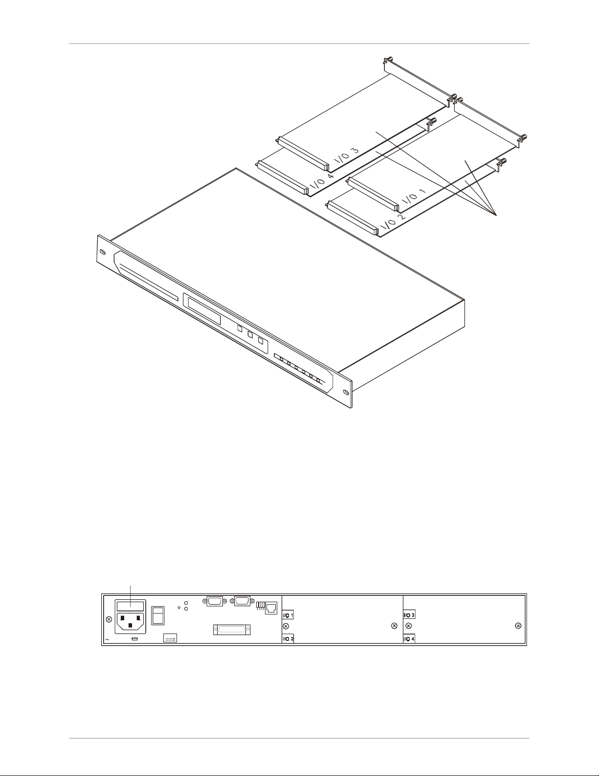
Figure 2-1. Attachment of Brackets .................................................................................. 2-12
Figure 2-2. Typical KPS Module, Location of Internal Jumper........................................... 2-13
Figure 2-3. Module KCL.2, Internal Switch and Jumpers .................................................. 2-14
Figure 2-4. KPS Modules, Rear Panels.............................................................................. 2-17
Figure 2-5. Module KCL.2, Rear Panel ............................................................................. 2-18
Figure 2-6. MX-2104 Enclosure, Typical Rear View.......................................................... 2-19
MX-2100/2104 Installation and Operation Manual v
Page 14

Table of Contents
Figure 3-1. Organization of Front Panel Menu (Part I) ........................................................ 3-4
Figure 3-2. Organization of Front Panel Menu (Part II) ....................................................... 3-5
Figure 3-3. Organization of Front Panel Menu (Part III) ...................................................... 3-6
Figure 4-1. MX-2100 Front Panel....................................................................................... 4-7
Figure 4-2. MX-2104 Front Panel....................................................................................... 4-7
Figure 4-3. Indicator Functions ..........................................................................................4-8
Figure 5-1. Local Main Link Loop, Signal Path.................................................................... 5-9
Figure 5-2. Remote Main Link Loop, Signal Paths ............................................................ 5-10
Figure 5-3. Main Link Modem Loop 3, Signal Path........................................................... 5-11
Figure 5-4. Main Link Modem Loop 2, Signal Path........................................................... 5-12
Figure 5-5. I/O Module, Local Loop on Individual Channel.............................................. 5-13
Figure 5-6. I/O Module, Remote Loop on Individual Channel..........................................5-13
Figure 5-7. Voice I/O Module, Test Tone Injection Path................................................... 5-15
Figure C-1. IP Address Classes............................................................................................C-5
Figure C-2. Management System Topology Using Subnetting .............................................C-7
List of Tables
Table 1-1. MX-2100 Multiplexing Data............................................................................ 1-17
Table 1-2. Bandwidth Allocations .................................................................................... 1-19
Table 1-3. Example of Bandwidth Allocations ..................................................................1-20
Table 1-4. KML.F Fiber-Optic Interface Characteristics .................................................... 1-49
Table 2-1. Power Consumption of MX-2100 Modules ....................................................... 2-4
Table 2-2. Nominal Power Consumption of Power Supply Modules .................................. 2-6
Table 2-3. DCE and DTE Interfacing Mode - Control Lines ................................................ 2-9
Table 2-4. MNG Connector - Control Lines .....................................................................2-11
Table 2-5. Module KCL.2, Internal Switch and Jumper Functions..................................... 2-14
Table 2-6. KPS Modules, Rear Panels............................................................................... 2-16
Table 2-7. Module KCL.2, Rear Panel ..............................................................................2-18
Table 2-8. MX-2104, Rear Panel Components ................................................................. 2-20
Table 2-9. Typical Terminal Control Sequences ............................................................... 2-22
Table 3-1. MX-2100 Front Panel Configuration Parameters................................................ 3-3
Table 3-2. Procedure for Performing Configuration Activity ............................................... 3-8
Table 4-1. General Command Options .............................................................................. 4-2
Table 4-2. MX-2100 Command Set Index.......................................................................... 4-4
Table 4-3. MX-2100 Controls, Connectors, and Indicators ................................................. 4-8
Table 4-4. Instructions for Displaying Current Configuration Parameters .......................... 4-11
vi MX-2100/2104 Installation and Operation Manual
Page 15

Table of Contents
Table 5-1. Deactivating all the Tests................................................................................... 5-3
Table 5-2. Activating / Deactivating the Monitoring of a Selected Channel ......................... 5-4
Table 5-3. Activating / Deactivating a Main Link Loop........................................................ 5-5
Table 5-4. Activating / Deactivating a Channel Loop .......................................................... 5-6
Table A-1. Common Logic Module KCL.2, Supervisory Port Connector Pin Allocations
for DCE Emulation............................................................................................. A-1
Table A-2. Common Logic Module KCL.2, Supervisory Port Connector Pin Allocations
for DTE Emulation .............................................................................................A-2
Table A-3. Common Logic Module KCL.2, MNG Connector Pin Allocations ...................... A-3
Table A-4. Alarm Relay Connector Pinout......................................................................... A-4
Table B-1. LCD Alarm Messages ........................................................................................ B-1
Table C-1. IP Address Class................................................................................................C-5
Table E-1. System Parameters ............................................................................................ E-1
Table E-2. Main Link Parameters........................................................................................ E-4
Table E-3. Supervisory Port Parameters .............................................................................. E-7
Table F-1. Call-out Parameters......................................................................................... F-10
Table F-2. Dial-out Parameters ........................................................................................ F-16
Table F-3. Network Parameters....................................................................................... F-26
Table F-4. Terminal Programmed Parameters .................................................................. F-28
Table F-5. System Parameters .......................................................................................... F-30
Table F-6. MX-2100 Default Configuration Used with Supervision Terminal .................... F-53
Table F-7. Codes Used by Typical Terminals.................................................................... F-54
MX-2100/2104 Installation and Operation Manual vii
Page 16

Table of Contents
viii MX-2100/2104 Installation and Operation Manual
Page 17

Chapter 1 General Information
1.1 Functional Description
MX-2100/2104 is an advanced, highly versatile user-configurable modular TDM
(Time Division Multiplex) system. The MX-2100/2104 system provides an efficient
and cost-effective method for transmitting data, voice and fax over digital data
services. Access to these services is provided over a variety of standard interfaces
(V.35, RS-530/V.36, RS-232/V.24, X.21, Standard DDS, codirectional G.703,
ISDN, fiber optic, T1, and E1), at data rates ranging from 9.6 to 1536 kbps.
Bandwidth utilization efficiency is 98.5%.
Main System Features
The MX-2100/2104 system can be equipped with various types of input/output
(I/O) modules that provide the required interface for the user data, fax, and voice
channels. The series of I/O modules includes:
• High-speed synchronous data modules operating at a rate of 2.4 through
614.4 kbps – the KHS series of modules
• Low-speed data modules (300 bps to 57.6 kbps or 64 kbps) synchronous and
asynchronous data channels, including statistical multiplexing modules – the
KLS series of modules
• ISDN interface modules – the KHS.U series and KVF.4/S0 series
• 2W and 4W multiple voice channel interface modules that can directly
connect to PBX lines and two-wire telephone sets – the KVC series of modules
• 2W and 4W interface voice/fax low bit rate KVF.4 and KVF.8 modules
• T1 and E1 PBX trunk interface KVF.5 and KVF.6 modules
• Token ring extender module, KTRE
• Ethernet Bridge/Router module, KMBE
• Bypass and multidrop module, KDI (not applicable for MX-2104).
Detailed information on the specific MX-2100 modules can be found in the
separate module Installation and Operation Manuals.
The 3U high MX-2100 unit can be equipped with up to 12 I/O modules. 1U high
MX-2104 unit can be equipped with up to 4 I/O modules.
Functional Description 1-1
Page 18
Chapter 1 General Information MX-2100/2104 Installation and Operation Manual
Note
In this manual, the generic term MX-2100 is used when the information is
applicable to both MX-2100 and MX-2104 equipment versions. If the information is
applicable to only a particular equipment version, this will be specified.
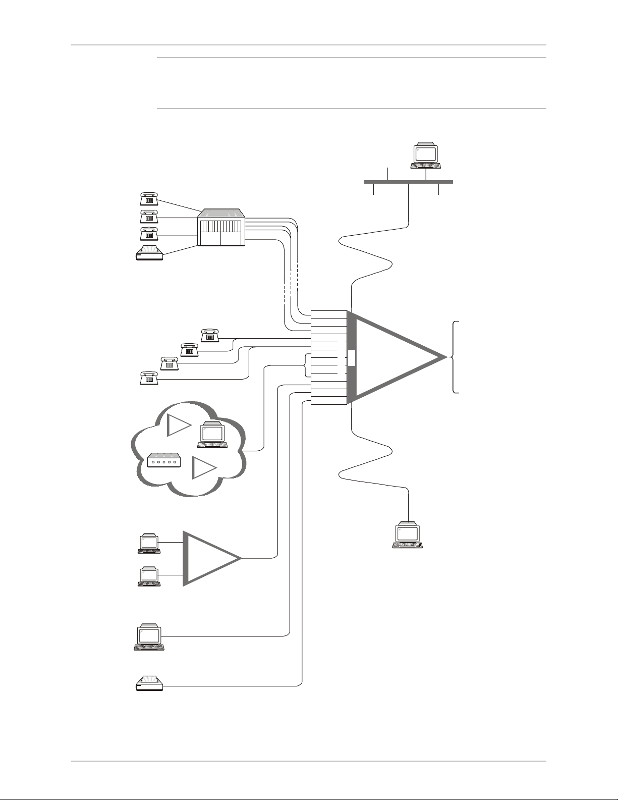
Figure 1-1 illustrates the basic capabilities of the MX-2100 system.
Network
Management Station
Ethernet
Network
Fax
Modem
Stat
Mux
Terminal
SDM
Mux
PAB X
Trunk
Line
Tie Lines
KVF.4
KVF.4
KVF.5
KVC.1M
KVC.1M
KLS.1
KLS.1
KLS.1
KLS.2
KHS.1
KHS.1
KVF.4
SP Port
or SLIP
KCL
I/O Modules
Ethernet Port
MX-2100
KML
-V.35
-RS-530/V.36
-RS-232/V.24
-X.21
-G.703 Codirectional
-Standard DDS
-ISDN
-E1
-T1
-Fiber-Optic
CAD/CAM
Fax
1-2 Functional Description
MX-2100
Supervision Terminal
or TELNET
or SNMP
Figure 1-1. MX-2100 System Applications
Page 19

MX-2100/2104 Installation and Operation Manual Chapter 1 General Information
The MX-2104 system can be equipped with only one main link. The 3U high
MX-2100 system can be equipped with two main link modules. Two main link
modules in an MX-2100 system, can be used in several ways:
• To provide hot-standby redundancy (backup) for the main link, with automatic or
manual switchover in case one of the links fails. For maximum flexibility, MX-2100
allows the preparation of a different configuration for use on the backup link. The
backup link can also use a switched data circuit. The switched circuit can be
established on a PSTN line, using analog modems, or on an ISDN line using an S
or U interface.
• To provide two independent links from the same MX-2100 enclosure. The two
links can operate at different data rates. The dual-link mode can also be used
for providing the equivalent of hot standby protection to critical data channels
(by enabling the priority bumping feature).
• To provide multidrop and bypass capabilities (using a dedicated KDI module).
In addition to main link redundancy, the MX-2100 system reliability can be further
enhanced by installing an additional power supply unit in the enclosure. The
power supplies share the load current, therefore when one of them fails or its
input voltage is disconnected, the other takes over the full load without
disturbance to MX-2100 operation.
The MX-2100/2104 system provides flexible system timing options, with several
main link, and channel timing modes.
The main link timing modes are DTE, DCE, and external DCE. In the DCE and
external DCE modes, the timing reference source can be selected by the user:
• Internal oscillator
• External (timing locked to one of the data channels)
• The other main link module (provided a KDI module is installed).
In addition to the main timing source, a fallback source can be selected. When the
timing mode is DTE or external DCE, buffers are inserted in the main link signal
paths, to absorb the expected jitter and timing instabilities. Normal buffer size is
±8 bits; for operation over satellite links, the receive buffer size can be increased to
±256 bits.
The timing modes available for the data channels are programmable, thereby
permitting each channel to be configured as either DCE (supplies receive and
transmit clocks to the user's equipment), DTE1 (supplies the receive clock and
accept a transmit clock), or DTE2 (accepts receive and transmit clocks from the
user's equipment), with buffered retiming of the received data. Connection to the
national network and to common-carrier data lines is also supported, with the
external clock selectable as the source for system timing.
For modules with ISDN, T1, E1, and fiber-optic interfaces, a loopback timing
mode is available. This mode enables locking the MX-2100 timing to the accurate
timing provided by the network to which the interface is connected.
Functional Description 1-3
Page 20

Chapter 1 General Information MX-2100/2104 Installation and Operation Manual
System Supervision and Configuration
The MX-2100 system is designed for unattended operation. A complete collection
of operating parameters configures the MX-2100 system and each of its modules.
This collection of operating parameters is determined by a database. This database
is stored in the non-volatile memory of the MX-2100 control module. MX-2100
can store two different databases, and can be configured to switch automatically
between the databases, in accordance with a predetermined daily schedule
("day/night" operation), or to use one of the databases only in case of switching to a
backup link.
MX-2100 supervision and minimal configuration functions can be performed from
its front panel, using three push-buttons and an LCD display. For more detailed
information, refer to Local Management on page 1-33.
MX-2100 stores alarms detected during operation in a buffer. The buffer serving
the front panel LCD can store one alarm of each type. The buffer for alarms to be
sent to a supervision terminal can hold up to 100 alarms. During regular operation,
a front panel indicator lights to indicate if there are any alarms in the alarm buffer.
The local operator can then review the contents of the alarm buffer on the front
panel LCD display, and can delete old alarms related to events that are no longer
present in the system.
In addition to the alarm buffer, the front-panel LED indicators display in real time
the main link and power supply status and alert when test loops are present in the
system. The front panel LED indicators can also be used to monitor on-line a
selected user channel. The monitored functions are transmit and receive data
activity, and the state of the RTS and DCD control lines (or E and M lines for voice
channels).
Local MX-2100 Management
A local MX-2100 can be managed by any of the following:
• MX-2100 front panel using push buttons and an LCD
• ASCII terminal connection to the local MX-2100
• TELNET connection to the local MX-2100. The connection can be via SLIP or
via an Ethernet LAN. The local MX-2100 requires an IP address. For
information on assigning an IP address, refer to the DEF AGENT command in
the Command Set Description appendix.
• SNMP network management station connected to the local MX-2100. The
connection can be via SLIP or via an Ethernet LAN. The local MX-2100
requires an IP address. For information on assigning an IP address, refer to the
DEF AGENT command in the Command Set Description appendix.
Remote MX-2100 Management
A remote MX-2100 can be managed either in-band or out-of-band. For both, the
remote MX-2100 requires an IP address. For information on assigning an IP
address, refer to the DEF AGENT command in the Command Set Description
appendix.
1-4 Functional Description
Page 21
MX-2100/2104 Installation and Operation Manual Chapter 1 General Information
In-Band Management
In-band management of a remote MX-2100 is performed via the local MX-2100
and the data frame. A connection to the local MX-2100 can be made through:
• An Ethernet LAN
• A SLIP connection.
In both cases, management can be performed via TELNET. Some of the bandwidth
of the main link between the two MX-2100s is used to relay the management
information.
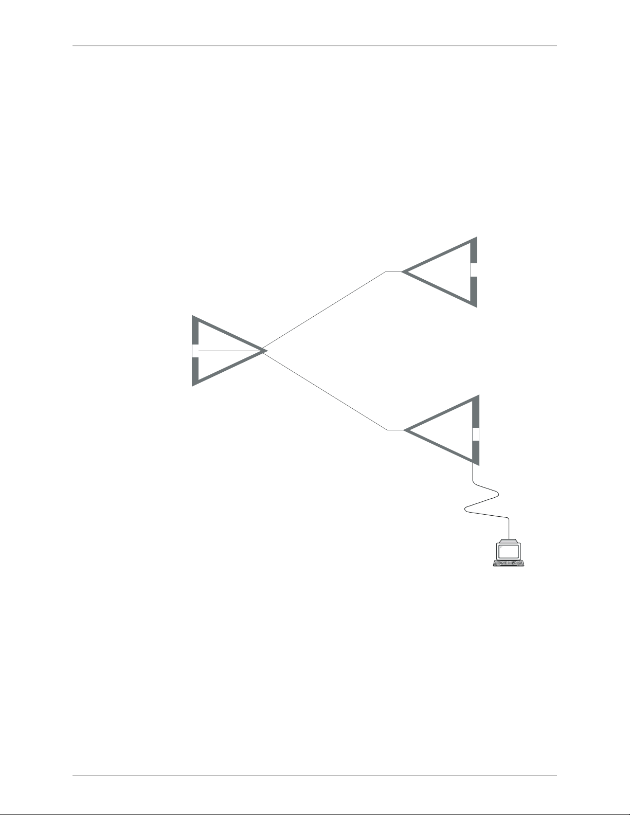
In a “V” configuration, any one of the three MX-2100s can be considered the local
MX-2100. The other two MX-2100s can be managed through the local MX-2100.
KCL
Remote
MX-2100
A
Main Link
Remote
MX-2100
A
B
Main Link
B
Local
MX-2100
KCL
KCL
Supervision Terminal
or TELNET
or SNMP
Figure 1-2. “V” Configuration
The main link between the local MX-2100 and the remote MX-2100 can also be
used to download software.
Out-of-Band Management
There are several options for managing a remote MX-2100 out-of-band:
• Using a network management station or TELNET over a LAN connected to the
remote MX-2100. The remote MX-2100 requires an IP address. For
information on assigning an IP address, refer to the DEF AGENT command in
the Command Set Description appendix.
Functional Description 1-5
Page 22

Chapter 1 General Information MX-2100/2104 Installation and Operation Manual
• Using a network management station or TELNET via a SLIP connection to the
remote MX-2100. The remote MX-2100 requires an IP address. For
information on assigning an IP address, refer to the DEF AGENT command in
the Command Set Description appendix.
• Using an ASCII terminal via a modem connection to the SP port.
Diagnostic Capabilities
The MX-2100 system provides extensive diagnostics, supervision and maintenance
capabilities for easy maintenance and rapid detection and location of faults.
MX-2100 diagnostics include automatic self-test upon power-up, and on-line
monitoring of critical functions. The system generates time stamped alarm
messages that cover all the significant system events. The time stamp is provided
by a real-time clock with battery backup. The system operator can then perform
comprehensive testing on each type of module, to determine the cause of the
alarm messages and return the system to normal operation.
Various types of test loops are provided, including modem loops 2 and 3 per
ITU-T Rec. V.54 for rapid isolation of the fault area, tone injection for rapid testing
of voice interface modules, and pseudo-random sequence transmission test for
checking the proper operation of data interface modules, and detection of bit
errors.
1.2 Physical Description
MX-2100, General Description
The MX-2100 system consists of a 19" (3U) enclosure that contains 18 module
slots. Five of the slots (slots 1 through 5) are assigned to the system modules:
• The control subsystem
• The main link (aggregate) interface subsystem
• The system power supplies.
Two slots each are assigned for KML and KPS modules, respectively, to provide
support for the redundancy option:
• Slots 1 and 2 - for KPS modules
• Slots 3 and 4 - for KML modules.
One slot (slot 6) is assigned for an options module (e.g., for the KDI or KAI
modules). The other 12 slots are intended for I/O modules. Each I/O slot can
accept any type of I/O module. All the modules are inserted through the rear
panel. The cable connections are also made through the rear panel.
Figure 1-3 shows a general view of a MX-2100, and identifies the functions of the
enclosure slot.
1-6 Physical Description
Page 23
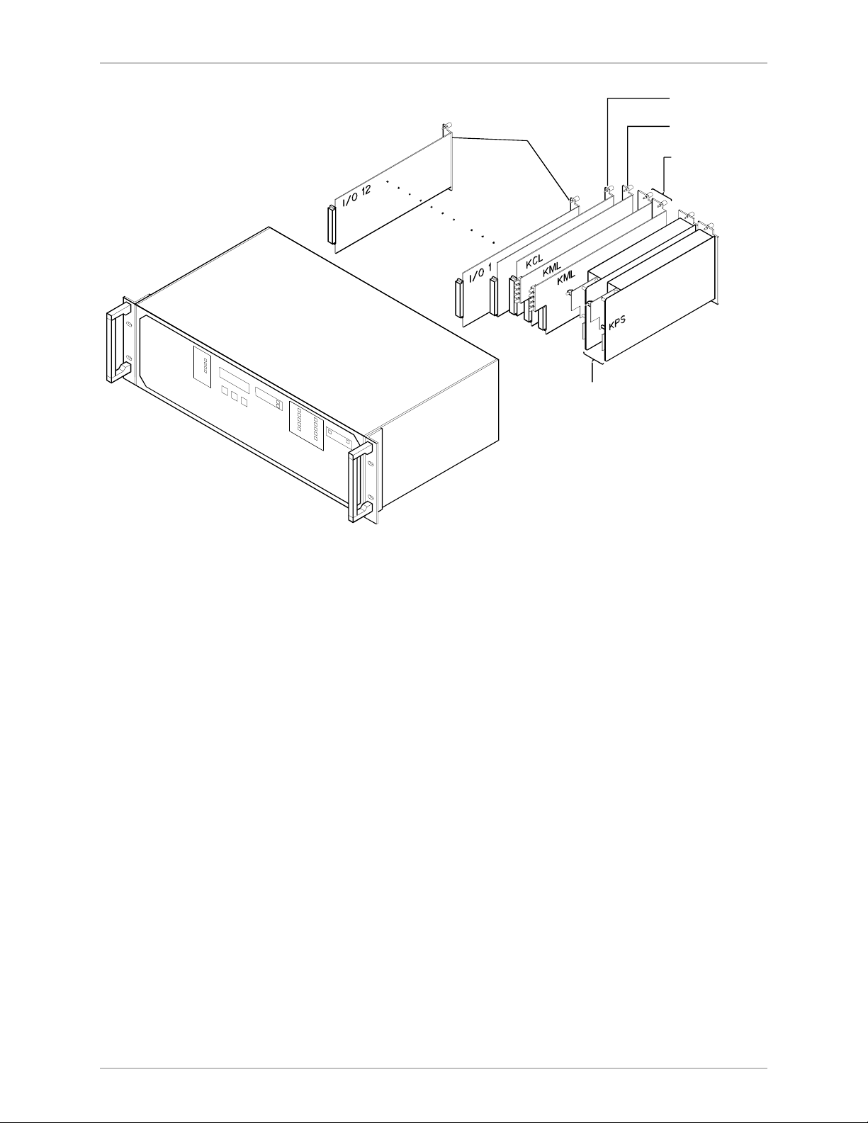
MX-2100/2104 Installation and Operation Manual Chapter 1 General Information
Options
Module
12 I/O
Modules
Power Supply
Sub-system
Common
Logic
Main Link
Interface
Sub-system
Figure 1-3. MX-2100 Enclosure with Modules, General View
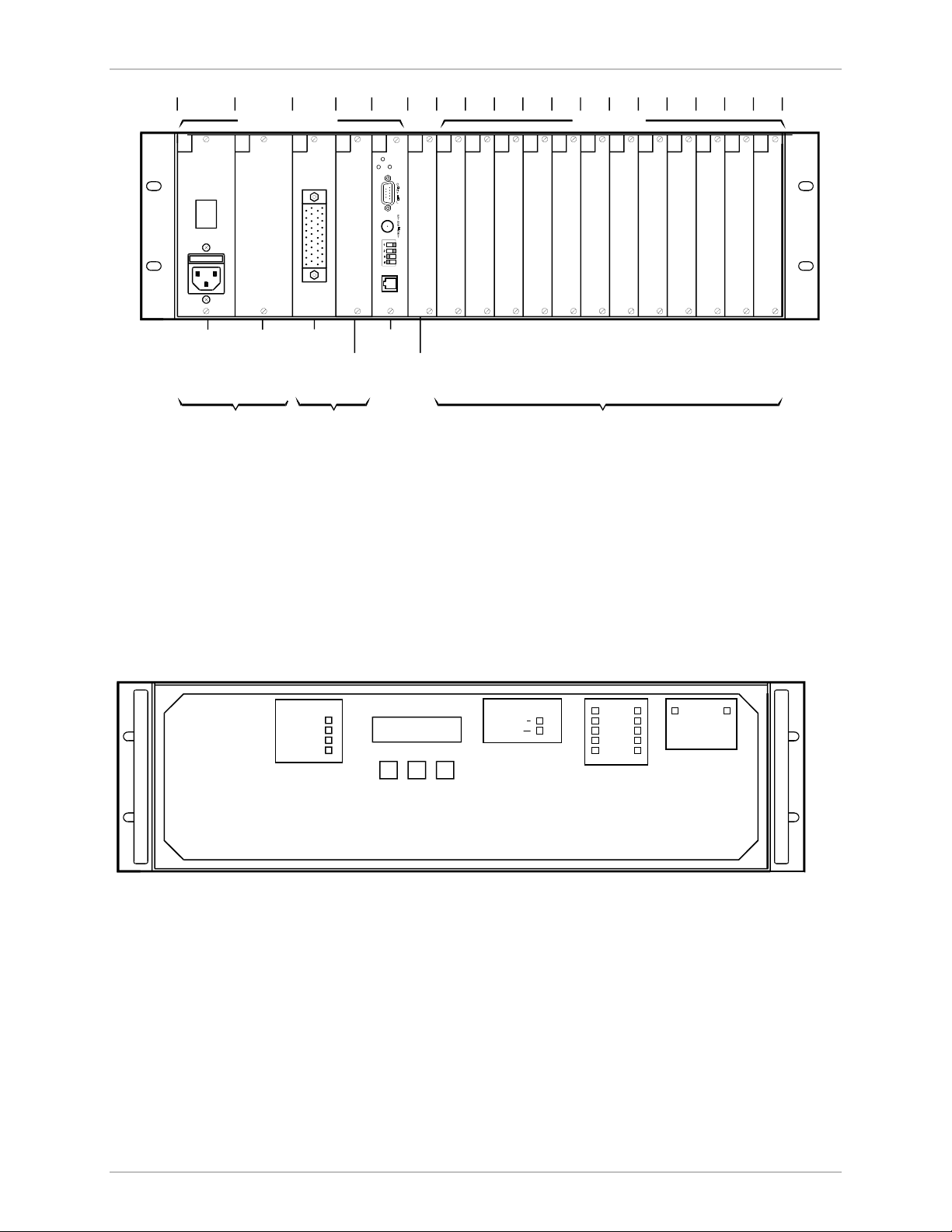
MX-2100 Rear Panel
Figure 1-4 shows a typical rear panel of the MX-2100 enclosure and identifies the
slots and their use.
Note the labels which designate the type of module that can be installed in each
slot; in addition, each slot is keyed, therefore it is not possible to install the wrong
module type.
Physical Description 1-7
Page 24
Chapter 1 General Information MX-2100/2104 Installation and Operation Manual
Slot 1
2 3 4 5 6 7 8 9 10 11 12 13 14 15 16 17 18
System Slots I/O Slots
1
PS-A
Power
Supply
2
PS-B
POWER
Redundant
Power
Supply
(Optional)
Power Supply
Sub-system
3
ML-AKPS
KML.1
KML
Module
Main Link Interface
Sub-system
MX-2100 Front Panel
The front panel of the MX-2100 enclosure includes an LCD, three push-buttons,
and labels for the show-through areas for the status indicators located on each
system module. Note that the indicators are arranged in groups (one group for
each system module), that are positioned before the corresponding module slot.
4
ML-B5CL6OP
Redundant
KML Module
(Optional)
KCL.2
RESET
ALARM
TEST
ALM RLY
KCL
Module
7
I/O18I/O29I/O310I/O411I/O512I/O6
Options
Module
I/O Modules
as Required
Figure 1-4. MX-2100 Enclosure, Rear View
13
I/O714I/O815I/O916I/O10
17
I/O1118I/O12
Figure 1-5 shows the front panel of the MX-2100 enclosure. Refer to the Operation
chapter for a description of the front panel functions.
DATAVOICE
TXD
RXD
RTSM-LEAD
E-LEAD DCD
CHANNEL
CURSOR SCROLL ENTER
Figure 1-5. MX-2100 Enclosure Front Panel
MX-2104, General Description
The MX-2104 system consists of a 19" 1U enclosure with 4 slots for the installation
of I/O modules. All the modules are inserted through the rear panel. The cable
connections are also made through the rear panel. The front panel includes a
control section with three push-buttons and a two-row LCD display
(16 characters per row), and status and alarm indicators.
STATUS
ALARM
TEST
SYSTEM
ON LINE
LOCAL LOS
REMOTE LOS
B
MAIN LINK
TXD
RXD
A
ON LINE
BA
POWER SUPPLY
The following figure shows a general view of a MX-2104 enclosure.
1-8 Physical Description
Page 25
MX-2100/2104 Installation and Operation Manual Chapter 1 General Information
4 I/O Modules
The MX-2104 enclosure contains the control sub-system, the main link (aggregate)
sub-system and the system power supply.
The main link sub-system performs main link interfacing, multiplexing and
demultiplexing functions, and provides the timing signals used by the I/O modules
installed in the enclosure.
MX-2104 Rear Panel
The following figure shows a typical rear view of the MX-2104 enclosure and
identifies the I/O slots.
FUSE
RST
ALM
TST
100-24 0VAC 0.8A T 25 0V
∼
Power
Figure 1-6 MX-2104 Enclosure, General View
ON
X.21
MNG
1234
ALM RLY
CONTROL
Figure 1-7. MX-2104 Enclosure, Rear View
Physical Description 1-9
Page 26

Chapter 1 General Information MX-2100/2104 Installation and Operation Manual
MX-2104 Front Panel
The following figure shows the front panel of the MX-2104 enclosure. The front
panel includes an LCD, three push-buttons, and status indicators. Refer to the
Operation chapter for a description of the front panel functions.
Common Logic Modules
The MX enclosure requires one KCL.2 type common logic module. The main
functions of the KCL.2 module are control of:
• Multiplexing/demultiplexing operations
• System management
• Interfacing with the optional external system management.
The KCL.2 module stores the MX-2100 database in non-volatile memory
(NVRAM). The configuration information stored in the NVRAM is downloaded to
the module installed in MX-2100 upon turn-on or after system reset. Therefore,
during troubleshooting activities, it is possible to temporarily remove the KCL.2
module from the MX-2100 enclosure without disrupting system operation. If it is
necessary to replace the KCL.2 module, the database can be transferred to a new
module by installing the NVRAM taken from the original module in the
replacement module.
CURSOR SCROLL ENTER
REM
LOS
LOC
Figure 1-8. MX-2104 Enclosure Front Panel
RX TX
ON
LINE
TEST
ALARM
Main Link Modules
The enclosure can accept one KML type main link interface module or, for
MX-2100, two KML type main link interface modules. In addition to main link
interfacing, the KML module performs the multiplexing and demultiplexing
functions and provides the timing signals used by the other modules installed in
the enclosure. Two KML modules are necessary for dual link configurations and for
main link redundancy.
The following main link interface modules are available:
KML.1 - V.35 main link interface module
KML.2 - V.24/RS-232 main link interface module
KML.3 - V.36/RS-422/RS-530 main link interface module
KML.4 - X.21 main link interface module
KML.5 - G.703 codirectional main link interface module
KML.6 - Standard DDS CSU/DSU main link interface module
KML.7 - T1 main link interface module
KML.8 - E1 main link interface module.
1-10 Physical Description
Page 27

MX-2100/2104 Installation and Operation Manual Chapter 1 General Information
KML.10 - ISDN main link interface module. The module can be ordered in two
versions:
• KML.10/S with ISDN S-type interface. The "S" interface operates as Terminal
Adapter (TE side), intended for connection to standard Network Termination
(NT) unit.
• KML.10/U with ISDN U-type interface. The "U" interface operates as Network
Termination (NT side) unit, intended for connection to standard Line
Termination (LT) unit.
KML.F - Fiber-optic main link interface module (not for MX-2104). The module
can be ordered with various types of optical interfaces (laser or LED transmitters
for single-mode and multi-mode fiber-optic cable).
For more information, see each main link module’s Installation and Operation
Manual.
Power Supply Modules
The MX-2100 enclosure can accept one or two KPS type power supply modules.
Several types of power supply modules are available:
KPS.3 - 25W power supply module for -48 VDC power
KPS.4 - 50W power supply module for 100 to 240 VAC mains
KPS.5 - 25W power supply module for -24 VDC power
KPS.6 - 56W power supply module for 100 to 240 VAC mains
KPS.7 - 56W power supply module for -48 VDC mains.
Two KPS modules are necessary for redundancy: when both modules are
operational, they share the load, whereas in case of failure or loss of input power
the remaining module continues to supply the power alone and there is no
redundancy. Switch-over is automatic and does not disturb normal operation.
The MX-2104 enclosure includes one power supply. The available types are:
• AC - 30W power supply for 100 to 240 VAC mains
• 48 - 40W power supply for -48 VDC mains.
In addition to power supply modules, the MX-2100 enclosure supports one
KM-Ringer module, for providing line feed and ring voltages for voice channels
and phantom feed for ISDN lines. This module is available in AC (115 to 230 VAC)
and DC (-24 VDC or -48 VDC) input voltage versions. The KM-Ringer can be
installed as a plug-in module for MX-2100, or located on shelves or desktops.
Physical Description 1-11
Page 28

Chapter 1 General Information MX-2100/2104 Installation and Operation Manual
Option Modules (not for MX-2104)
The 3U MX-2100 system can accept two types of options module:
KAI
Alarm indication module for installation in the options position, or in any I/O slot.
The KAI includes indicators similar to those located on the MX-2100 front panel.
These indicators repeat all the relevant MX-2100 front panel indications on the
rear panel, and thus complement the indicators available on the rear panels of the
other modules. Maintenance activities are thus expedited, as all the MX-2100
indications become readily available on one side of the equipment.
KDI
Bypass and multidrop module. The KDI module can be installed in the option slot,
or in any I/O slot. The KDI module enables direct transfer (bypassing) of a group of
main link frame bits, in both directions, between the two main links of MX-2100.
Channels that are not bypassed are connected to I/O modules of MX-2100.
The KDI module is available in two versions:
• KDI version: supports only the bypassing function
• KDI/M version: also includes a data channel interface for one multidrop channel.
The multidrop channel is compatible with the data channels of the KLS.1/NEW
low-speed data module, and supports data rates in the range of 0.3 to 64 kbps. As
is standard practice in a multidrop application, the receive path of the local
multidrop channel continuously receives the data transferred in its allocated
bandwidth on the desired main link (the same data is also bypassed to the other
link, to make it available downstream), but its transmit path is connected to the
main link only when the RTS line in the local interface is asserted.
I/O Modules
For more information, see the option module’s Installation and Operation Manual.
MX-2100 supports up to 12 user-selected I/O modules. MX-2104 supports up to 4
user-selected I/O modules. Both units can accept any combination of the following
types of I/O modules with power supply limitations.
KVC.1 - ADPCM or PCM voice interface module, provides two voice channels. For
more information, refer to the KVC.1 Installation and Operation Manual.
The following versions are available:
− KVC.1/E&M: four-wire or two-wire interface with E&M signaling per
RS-464 Types I, II, III and V, and British Telecom SSDC5
− KVC.1/FXS: two-wire interface for direct connection to a telephone set
− KVC.1/FXO: two-wire interface for direct connection to a PBX extension
line.
1-12 Physical Description
Page 29

MX-2100/2104 Installation and Operation Manual Chapter 1 General Information
• KVC.1M - ADPCM or PCM voice interface module, provides one or two voice
channels and support error-free fax transmission. For more information, refer
to the KVC.1M Installation and Operation Manual.
The following versions are available:
− KVC.1M/E&M: two voice channel with four-wire or two-wire interface with
E&M signaling per RS-464 Types I, II, III and V, and British Telecom SSDC5
− KVC.1M/E&M48: similar to the KVC.1M/E&M, except that it requires an
external -48 VDC source to supply the signaling voltage for increasing the
maximum allowed line length
− KVC.1M/FXS: two voice channels with two-wire interface for direct
connection to a telephone set
− KVC.1M/FXSP: similar to KVC.1M/FXS, except that it has an internal ringer
and line feed supply
− KVC.1M/FXO: two voice channels with two-wire interface and FXO loop
start signaling for direct connection to a PBX extension line.
• KVC.3 - Low-bit rate voice module, provides two high-quality compressed
voice channels. For more information, refer to the KVC.3 Installation and
Operation Manual.
The following versions are available:
− KVC.3/E&M: two voice channels with four-wire or two-wire interface with
E&M signaling per RS-464 Types I, II, III and V, and British Telecom SSDC5
− KVC.3/FXS: two voice channels with two-wire interface for direct
connection to a telephone set
− KVC.3/FXSP: similar to KVC.3/FXS, except that it has an internal ringer and line
feed supply
− KVC.3/FXO: two voice channels with two-wire interface and FXO loop start
signaling for direct connection to a PBX extension line.
• KLS.1 - Low-speed RS-232 data module. For more information, refer to the
KLS.1 Installation and Operation Manual.
• KLS.2 - Low-speed RS-232 four-channel asynchronous statistical data module.
For more information, refer to the KLS.2 Installation and Operation Manual.
• KHS.1 - High-speed data interface module, provides two high-speed V.35,
RS-530 or RS-449/RS-422 data channels. For more information, refer to the
KHS.1 Installation and Operation Manual.
• KHS.2 - Two-channel synchronous data module. For more information, refer
to the KHS.2 Installation and Operation Manual.
Physical Description 1-13
Page 30

Chapter 1 General Information MX-2100/2104 Installation and Operation Manual
• KHS.U - Data interface module, provides one or two ISDN basic access rate
type "U" interfaces. The KHS.U module enables the extension of ISDN lines
over non-ISDN facilities. For more information, refer to the KHS.U Installation
and Operation Manual.
The following versions are available:
− KHS.U/S with one "U" interface
− KHS.U/D with two "U" interfaces.
• KHS.703 – High-speed data module that provides two independent 64 kbps
codirectional data channels per ITU-T Rec. G.703. Each module is terminated
with an RJ-45 eight pin connector. For more information, refer to the KHS.703
Installation and Operation Guide, further on in this manual.
• KVF.4 - Voice/fax relay module using advanced digital signal processing (DSP)
techniques (MPMLQ in accordance with ITU-T Rec. G.723.1) to provide one
or two channels for transmission of voice and standard Group III fax signals
over the MX-2100 link with automatic switch-over between voice and fax
modes. For more information, refer to the KVF.4 Installation and Operation
Manual.
The following versions are available:
− KVF.4/E&M: two channels with four-wire or two-wire interface with E&M
signaling per RS-464 Types I, II, III and V, and British Telecom SSDC5
− KVF.4/E&M/E: similar to the KVF.4/E&M, except that it requires an external
-48 VDC source to supply the signaling voltage for increasing the maximum
allowed line length
− KVF.4/FXS: two voice channels with two-wire interface for direct
connection to a telephone set
− KVF.4/FXS3: similar to KVF.4/FXS, except that it supports pulse metering
and polarity reversal
− KVF.4/FXSP: similar to KVF.4/FXS, except that it has an internal ringer and
line feed supply
− KVF.4/FXSW: one channel similar to the channels of the KVF.4/FXS, and
one two-wire interface operating with FXO signaling, intended for
connection to the PSTN, or to a PBX extension line
− KVF.4/FXO: two channels with two-wire interface and FXO loop start
signaling for direct connection to a PBX extension line
− KVF.4/FXO3: similar to KVF.4/FXO, except that it supports pulse metering
and polarity reversal
1-14 Physical Description
− KVF.4/S0: one ISDN basic rate access type "S" interface for direct
connection to an ISDN PBX.
Page 31

MX-2100/2104 Installation and Operation Manual Chapter 1 General Information
• KVF.5 - Voice/fax relay module with T1 or E1 PBX trunk interface, uses
advanced digital signal processing (DSP) techniques (MPMLQ - Multipulse
Maximum Likelihood Quantization in accordance with ITU-T Rec. G.723.1) to
allow the transmission of Group III facsimile and high-quality compressed
voice signals while requiring, for each channel, a bandwidth of only 4.8, 6.4,
7.2, 9.6, or 12.8 kbps on the MX-2100 main link. For more information, refer
to the KVF.5 Installation and Operation Manual.
The following versions are available:
− KVF.5/T1/M: KVF.5 "master" module with balanced T1 sub link interface,
for connection to PBXs
− KVF.5/E1/M: KVF.5 "master" module with balanced and unbalanced E1 sub
link interfaces, for connection to PBXs
− KVF.5/T1/S: basic KVF.5 "slave" module without trunk interface
− KVF.5/E1/S: basic KVF.5 "slave" module without trunk interface.
• KVF.6 - Voice/fax compression module, provides direct connection to E1/T1
PBX trunks. For more information, refer to the Installation and Operation
Manual.
• KVF.8 – Provides high quality digital compression of eight analog voice/fax
channels. For more information, refer to the KVF.8 Installation and Operation
Manual.
• KTRE - Token ring extender module. For more information, refer to the KTRE
Installation and Operation Manual.
• KMBE - Ethernet Bridge/Router module. For more information, refer to the
KMBE Installation and Operation Manual.
Physical Description 1-15
Page 32

Chapter 1 General Information MX-2100/2104 Installation and Operation Manual
I/O
M
d
l
1.3 Application Considerations
Basic MX-2100 System
Basic System Structure
The basic MX-2100 system consists of two MX-2100 units connected by a single
link, as shown in Figure 1-9.
es
u
o
KML
Modem
Modem
KML
I/O Modules
MX-2100
MX-2100
Figure 1-9. Basic MX-2100 System Structure
System Multiplexing Capabilities
To provide the flexibility necessary to support up to 12 I/O modules of various
types for the MX-2100 or up to 4 I/O modules of various types for the MX-2104,
with each module capable of operation in several modes, the system uses
permanent on-demand allocation of main link bandwidth. This means that
bandwidth is permanently allocated to the active channels of each module when
the module is inserted into the enclosure, and the allocation is made in
accordance with the selected data rate and the end-to-end signaling requirements
of each channel. The main link bandwidth is dynamically reallocated when a
change occurs in the number of modules or of active module channels, or when
the operating mode of the main link or of the modules are changed. For special
applications, the user can disable the automatic allocation and perform manual
allocation.
Although in general, dynamic on-demand bandwidth allocation requires that the
link is resynchronized after each change in allocation, the allocation algorithm
used by MX-2100 has been optimally designed so that it does not require
resynchronization. It only requires reallocation of time slots, thereby reducing the
disruption to other channels when the bandwidth required by a module or a
module channel changes. In many cases, the required changes are made even
without time slot reallocation: for example, disconnecting or reducing the data rate
carried by a channel never requires reallocation.
Bandwidth allocation is performed by organizing the data in frames. Frame length
varies with the main link data rate, as listed in Table 1-1.
1-16 Application Considerations
Page 33

MX-2100/2104 Installation and Operation Manual Chapter 1 General Information
Note
If you are using automatic frame allocation, special precautions must be taken to
ensure proper operation of the link:
In general, the two MX-2100 units must be identically equipped. Both units must
include the same modules with the following exceptions:
– The KLS.1 in the local MX-2100 unit can work with the KLS.2 in the
remote MX-2100 unit.
– The KVF.4 in the local MX-2100 unit can work with the KVF.5 in the
remote MX-2100 unit.
– The KMBE in the local MX-2100 unit can work with the KHS.2 in the
remote MX-2100 unit.
– The KVF.6 in the local MX-2100 unit can work with the KVF.8 in the
remote MX-2100 unit.
The order of the modules must be the same in both units, and their connections to
main link modules must be the same.
The modules and module channels installed in the two MX-2100 units must be
identically configured, except for parameters that control local interfacing
characteristics, such as the channel interface type, the timing modes, etc.
After each change of configuration that affects the bandwidth utilization, e.g.,
addition of a new channel, selection of a mode that requires end-to-end signaling,
etc., perform the REBUILD FRAME command on both MX-2100 units.
Table 1-1. MX-2100 Multiplexing Data
Main Link Rate Frame Length Bandwidth
Allocation Unit
9.6 kbps 24 bits 0.4 kbps 9.2 kbps (23 units)
14.4 kbps 36 bits 0.4 kbps 14.0 kbps (35 units)
19.2 kbps 48 bits 0.4 kbps 18.8 kbps (47 units)
28.8 kbps 72 bits 0.4 kbps 28.4 kbps (71 units)
32 kbps 80 bits 0.4 kbps 31.6 kbps (79 units)
48 kbps 60 bits 0.8 kbps 47.2 kbps (59 units)
56 kbps 70 bits 0.8 kbps 55.2 kbps (69 units)
64 kbps 80 bits 0.8 kbps 63.2 kbps (79 units)
128 kbps 160 bits 0.8 kbps 127.2 kbps (159 units)
192 kbps 240 bits 0.8 kbps 191.2 kbps (239 units)
256 kbps 160 bits 1.6 kbps 254.4 kbps (159 units)
384 kbps 240 bits 1.6 kbps 382.4 kbps (239 units)
512 kbps 160 bits 3.2 kbps 508.8 kbps (159 units)
768 kbps 240 bits 3.2 kbps 764.8 kbps (239 units)
1024 kbps 160 bits 6.4 kbps 1004.8 kbps (157 units)
Bandwidth Available
to User
1536 kbps 240 bits 6.4 kbps 1516.8 kbps (237 units)
The allocation of bandwidth is performed in distinct units. The bandwidth
allocation unit (BAU) is 0.4, 0.8, 1.6, 3.2 or 6.4 kbps, in accordance with the main
link data rate (see Table 1-1).
Application Considerations 1-17
Page 34

Chapter 1 General Information MX-2100/2104 Installation and Operation Manual
Bandwidth allocations must be made for the following uses:
• MX-2100 frame synchronization
• In-band management channel. This channel's main function is to allow a
connection to be made to the remote unit by TELNET, SNMP management or
TFTP via the download bandwidth allocation. Through in-band management,
some of the bandwidth of the main link between the local MX-2100 and the
remote MX-2100 is used to relay management information.
• Channel data
• Channel end-to-end signaling.
The following table provides bandwidth allocation information. The use of the
information presented in the table to calculate the bandwidth required for various
operating configurations is illustrated by a numerical example that follows the
table.
1-18 Application Considerations
Page 35

MX-2100/2104 Installation and Operation Manual Chapter 1 General Information
Table 1-2. Bandwidth Allocations
Use Allocation Units Allocation Rule
Frame
Synchronization
Management
Channel
Channel Data Channel Main Link Rate in kbps
9.6 to 32
All Modules
KHS.2 Only
Channel
End-to-End
Control Signals
1 Mandatory
Depends on Main Link Rate
(used Bandwidth Allocation Unit kbps rate in parenthesis)
48 to 192
(0.4)
300 bps
600 bps
1.2 kbps
2.4 kbps
4.8 kbps
6.4 kbps
7.2 kbps
8 kbps
9.6 kbps
14.4 kbps
16 kbps
19.2 kbps
24 kbps
28.8 kbps
32 kbps
38.4 kbps
48 kbps
56 kbps
57.6 kbps
64 kbps
67.2 kbps
76.8 kbps
86.4 kbps
96.0 kbps
105.6 kbps
115.2 kbps
124.8 kbps
128 kbps
160 kbps
192 kbps
224 kbps
240 kbps
272 kbps
304 kbps
336 kbps
368 kbps
N × 2.4
N × 4.8
N × 9.6
1 allocation unit per module or for each two channels of the
same module, when applicable (1 allocation unit can carry
up to four control signals, e.g., two signals for two channels)
3
3
3
6
12
16
18
20
24
36
40
48
60
72
80
–
–
–
–
–
–
–
–
–
–
–
–
–
–
–
–
–
–
–
–
–
N × 6
–
–
(0.8)
3
3
3
3
6
8
9
10
12
18
20
24
30
36
40
48
60
70
72
80
84
96
108
120
132
144
156
–
–
–
–
–
–
–
–
–
N × 3
–
–
256, 384
(1.6)
3
3
3
3
3
4
–
5
6
9
10
12
15
18
20
24
30
35
36
40
42
48
54
60
66
72
78
80
100
120
140
150
170
190
210
230
–
N × 3
–
512, 768
(3.2)
3
3
3
3
3
2
–
–
3
–
5
6
–
9
10
12
15
N/A
18
20
21
24
27
30
33
36
39
40
50
60
70
75
85
95
105
115
–
–
N × 3
Optional
(at least 9.6 kbps
recommended)
1024, 1536
(6.4)
–
–
–
–
–
–
–
–
–
–
–
3
–
–
5
6
–
–
9
10
–
12
–
15
–
18
–
20
25
30
35
–
–
–
–
–
For each channel that requires
end-to-end signaling, including
voice channels
In accordance with
channel data rate.
Theoretical
minimum is 1
allocation unit per
active channel. For
low rate data (i.e.,
for data rates lower
than the bandwidth
allocation unit),
oversampling is used
to achieve an integer
number of bit
samples, e.g., when
the bandwidth
allocation unit is
0.8 kbps and the
channel data rate is
300 bps, the
effective bandwidth
used is 8 times
higher, 2.4 kbps.
2.4 kbps translate to
3 allocation units.
Therefore, the effect
of oversampling is to
increase the
bandwidth used to
transfer low-rate
channels.
64 kbps rate
available only for
main link rates of
128 kbps and higher
Application Considerations 1-19
Page 36

Chapter 1 General Information MX-2100/2104 Installation and Operation Manual
Note
Modules which transmit the signaling information in-band, e.g., KVF.1 and KVC.2,
do not require bandwidth allocation for channel end-to-end signaling.
Bandwidth Allocation Example
A MX-2100 enclosure equipped as follows is connected to a 256 kbps link (BAU
used with this link rate is 1.6 kbps). The following table lists the required
bandwidth allocation.
Table 1-3. Example of Bandwidth Allocations
Modules Installed in Enclosure Allocation Units
Five KLS.1 with 4.8 kbps per channel (total of 10 channels);
seven channels (distributed among four modules)
require end-to-end signaling
Two KLS.1 with 9.6 kbps per channel (total of 4 channels),
no end-to-end signaling
One KLS.2 with composite data rate of 19.2 kbps 12 units
One KHS.1 with 64 kbps per channel, no end-to-end
signaling
One KVC.1 module at 32 kbps per channel 40 units
Total user allocation
Frame synchronization
Management channel (9.6 kbps)
Total capacity used
Reserve capacity 2 units (3.2 kbps)
Redundancy (not for MX-2104)
The minimum MX-2100 system configuration requires only one KPS module, one
KCL module and one KML module. For critical applications, system availability can
be increased by installing redundant modules in the enclosure.
30 units
4 units signaling
24 units
40 units
1 unit signaling
151 units
1 units
6 units
158 units
The redundancy capability is available for two critical functions: the main link and
the power supply. A failure in either one of these functions, e.g., because of link
failure or loss of power, could disable the whole system. However, a failure in an
I/O module affects only a small part of the system, and can generally be overcome
by using alternate routes, putting unused capacity into service, etc.
The MX-2100 system is designed to automatically put a redundant module in
service in case the corresponding module fails, thereby ensuring continuous system
operation in the event of any single module failure. Moreover, redundant modules
may be inserted or removed even while the system operates, without disrupting
the traffic or degrading the system performance.
The utilization of the redundant modules is explained in the following section.
1-20 Application Considerations
Page 37

MX-2100/2104 Installation and Operation Manual Chapter 1 General Information
KPS Module Redundancy
The KPS module supplies the operating voltages to MX-2100. A single KPS module
can provide the full power requirements of an enclosure. However, a second KPS
module may be added. With a redundant KPS module, both modules are
connected to power and share the load when the system is operating. If one
module (or its power source) fails, the second module automatically takes up the
full load and there is no redundancy.
To maximize the protection conferred by the use of redundant power supply
modules, observe the following recommendations:
• Whenever possible, connect each of the two KPS modules to a different power
circuit. Thus, if the circuit breaker that protects one of the power circuits trips,
the other module continues to receive power.
• If -48 VDC battery backup is available, install one DC-powered KPS.3 module
and one AC-powered module. Make sure to select power supply modules with
comparable ratings, e.g., KPS.6 and KPS.7.
KML Module Redundancy
I/O Modules
Note
The KML module serves as the connecting link between the MX-2100 unit and the
communication channel. For extra protection, a second KML module, not
necessarily of the same type, may be installed in parallel to the primary KML
module. The two KML modules are then connected through two independent
links, which may even follow different paths, to two similar modules located at the
remote end of the link. In the switched backup mode, the two links can be
operated at different data rates.
KML A
KML B
MX-2100
Modem
Modem
Modem
Active Link
Redundant
(Standby) Link
Modem
KML A
KML B
Modem
Modem
MX-2100
Figure 1-10. Redundant MX-2100 System
In this mode, MLA and MLB rates should be the same!
I/O Modules
Each KML module is connected to an independent internal bus. The internal buses
reach each I/O module installed in the enclosure, therefore each module has
equal access to each KML module.
Application Considerations 1-21
Page 38

Chapter 1 General Information MX-2100/2104 Installation and Operation Manual
When redundancy is enabled, the redundant KML module is automatically
programmed exactly like the primary, but its bus is electrically disconnected from
the other modules installed in the enclosure. If the primary KML module (or its
communication) fails, the other modules are disconnected from the bus of the
failed module and connected to the bus of the redundant KML module, which
then takes over.
The operator of the MX-2100 unit can select the primary (active) KML module,
e.g., in order to switch back to the preferred link after redundancy switching has
occurred. This arrangement provides redundancy at both the module and the link
level.
Dual Link Operation (not for MX-2104)
Basic Dual-Link Configurations
As an option, MX-2100 allows independent operation of its two multiplexing
subsystems. Therefore, by connecting two main links to one MX-2100 equipped
with two KML modules it is possible to double the number of payload time slots.
Two dual-link topologies are possible:
• High capacity point-to-point link. A typical system configuration is shown in
Figure 1-11.
• Two independent links, as shown in Figure 1-12. The two links can operate at
different data rates.
Modules installed in the enclosure can be freely connected to either of the two
links, the only restriction being that all the subchannels of a given module must be
assigned to the same link.
I/O Modules
KML A
KML B
MX-2100
Modem
Modem
Modem
Modem
Modem
Modem
MX-2100
Figure 1-11. Dual Link, High Capacity Point-to-Point Application
KML A
KML B
I/O Modules
1-22 Application Considerations
Page 39

MX-2100/2104 Installation and Operation Manual Chapter 1 General Information
User Connected
to Location B
User Connected
to Location C
Location A
KML A
KML B
MX-2100
Figure 1-12. Dual Link System, Independent Link Application
Location B
MX-2100
Location A
MX-2100
Bypassing Configurations
Dual-link configurations also enable direct transfer of channel between the two
links (this is called bypassing). This function requires the presence of a KDI module
in MX-2100.
Figure 1-13 shows the operation of the basic bypassing configuration. In
Figure 1-13, some of the users at location A are connected to users at location B,
and other users at location A are connected, using the bypassing function of the
KDI module, to users at location C (the connection is full duplex). As explained
above, with respect to bypassing, the multidrop channel is handled either as a
bypassed channel, or as a dropped channel, depending on the state of the RTS
line.
The KDI module supports the bypassing of one contiguous block of bits from one
link to the other. The bypassed block is specified by three parameters:
• The position of the first bit (the starting bit) of the block to be bypassed in the
multiplexed frame of main link A
• The number of bits to be bypassed (the block size)
• The position of the first bit (the starting bit) of the block in the frame of main
link B. This may differ from the starting bit on main link A.
Application Considerations 1-23
Page 40

Chapter 1 General Information MX-2100/2104 Installation and Operation Manual
Connected
to Location B
Connected
to Location C
Location A
MX-2100
Link A
User Connected
to Location A
Bypassed Bits
KML A
KML B
Location B
Link B
MX-2100
User Connected
to Location C
Location C
MX-2100
User Connected
to Location B
User Connected
to Location A
Figure 1-13. Basic Bypassing Configuration
Figure 1-14 shows an example of bit routing between the various units.
Since the bypassing is bit-oriented, the two MX-2100 links can operate at different
data rates, but they must use bandwidth allocation units of equal sizes (refer to
Table 1-1 for allowable selections). Therefore, the bypassing can be performed
between links operating at rates within the same group of rates:
• 9.6, 14.4, 19.2, 28.8, or 32 kbps (0.4 kbps bandwidth allocation unit)
• 48, 56, 64, 128 or 192 kbps (0.8 kbps bandwidth allocation unit)
• 256 or 384 kbps (1.6 kbps bandwidth allocation unit)
• 512 or 768 kbps (3.2 kbps bandwidth allocation unit).
• 1024 or 1536 kbps (6.4 kbps bandwidth allocation unit).
In order for the user to be able to specify the allocation of main link bits to the
individual channels, the structure of the main link frame must be specified by the
user. Therefore, in a bypassing application the automatic bit allocation algorithm
used by MX-2100 must be disabled, and the allocation must be manually
performed. Manual allocation is required for every participating MX-2100.
1-24 Application Considerations
Page 41

MX-2100/2104 Installation and Operation Manual Chapter 1 General Information
Location A Location C
A-to-B A-to-C
Location B
Link A
Dropped
Info
The manual allocation is performed at the level of individual channels, therefore
the channels of a given I/O module can be routed to different MX-2100 units. This
is however possible only if the following conditions are met:
• The I/O modules are not located at a bypassing location, i.e., are not installed
• The I/O modules whose channels are to be routed to different MX-2100 units
Bypassed
Info
A-to-C
Dropped
Info
B-to-C
Link B
Figure 1-14. Bypassing Parameters
in a MX-2100 unit with an active KDI module.
do not use end-to-end transmission of control signals; otherwise, all the
channels of an I/O module using end-to-end transmission of control signals
must be routed to a single module (this implies that they must be bypassed or
dropped together at the same MX-2100).
In the typical bypassing application shown in Figure 1-15, two MX-2104
multiplexers, located at two branch offices, are connected to MX-2100 located at
the central site. The KDI module installed in MX-2100 located at the central site
provides a direct connection between the two MX-2104 units via the central site
for selected channels. The connection is performed by transferring (bypassing) the
desired group of main link frame bits between the two main link modules. For
example, in Figure 1-15 the bypassed time slots could be used to connect between
the two KVF.4 modules identified by No. 2, which are installed in the two
MX-2104 units.
Application Considerations 1-25
Page 42

Chapter 1 General Information MX-2100/2104 Installation and Operation Manual
Remote Si te A
1
1
KVF.4
2
KVF.4
3
KVF.4
4
PABX
HOST
Central Site
1
5
3
6
4
7
KVF.4
KVF.4
KVF.4
KVF.4
KHS.1
KHS.1
KDI
KCL
MX-2100
KML A
KML B
MX-2104
Remote Si te B
KHS.1
KVF.4
KVF.4
KVF.4
KHS.1
PABX
5
2
6
7
PABX
MX-2104
Figure 1-15. Typical Bypassing Application
Channels that are not bypassed are connected to users connected to MX-2100 at
the central site: for example, the two channels of the KVF.4 module at location A
(identified by No. 3) are connected to the channels of the KVF.4 module also
identified by No. 3 which is installed at the central site, and the KHS.1 module at
location B (identified by No. 7) is connected to the KHS.1 module at the central
site.
Fully digital transmission for bypassing voice channels is an essential requirement
to the preservation of high-quality voice reproduction when low bit rate voice
compression is used, because it eliminates back-to-back analog interconnections at
intermediate locations, and the ensuing analog-to-digital and digital-to-analog
conversions. Full digital transmission has significant advantages for data channels as
well, because it does away with the cables that would otherwise be required for
the connection of data channels, and provides the equivalent of an electronic
cross-connect function (programmable by the same means used to control the
operation of MX-2100).
Multidrop Configurations
The KDI/M module version includes a data channel interface for multidrop
configurations. The multidrop channel is compatible with the data channels of the
KLS.1/NEW low-speed data module, and supports data rates in the range of 0.3 to
64 kbps.
As is standard practice in a multidrop application, the receive path of the local
multidrop channel continuously receives the traffic carried in the allocated
bandwidth on the desired main link, e.g., link A, and in addition the same data is
also bypassed to the other link, to make it available downstream. The transmit
path of the multidrop channel is connected to main link A only when the RTS line
in the local interface is asserted. A typical bypassing and multidrop configuration is
shown in Figure 1-16.
1-26 Application Considerations
Page 43

MX-2100/2104 Installation and Operation Manual Chapter 1 General Information
In the application shown in Figure 1-16, the multidrop channel of the KDI module
is used to connect between the host computer (connected to a data channel of a
KLS.1/NEW module installed in MX-2100 situated at the central site), and several
data terminals located at other locations. The communication is based on a polled
protocol, whereby the host operates as the master and arbitrates the traffic on the
multidrop link by addressing the Dates one at a time. The multidrop feature
operates as follows:
• All the Dates connected along the link can receive the data sent by the host,
because all the multidrop channels of all MX-2100 are allocated bandwidth on
link A. In addition, the bandwidth allocated to the multidrop channels is also
designated for bypassing to link B, to enable all the downstream Dates to
receive the host.
• When a DTE connected to a KDI/M module has data to transmit toward the
host, it must assert its RTS line. The assertion of the RTS line in the multidrop
channel interface changes the routing of the main link data by the
corresponding KDI/M module:
− The KDI/M module disconnects the bypassing connection of the multidrop
channel data to main link B, and the channel data is dropped locally. As
long as the RTS line is asserted, the DTE remains connected to main link A,
just as in a point-to-point connection.
− When the RTS line is deasserted (at the end of DTE transmission), the
KDI/M module stops dropping the channel data, and the bypassing path is
re-established.
KML
KDI
KCL
KLS.1
HOST
MX-2100
KML A
KML B
KDI
KCL
MX-2100
DTE DTE DTE
Figure 1-16. Typical KDI Bypassing and Multidrop Application
Priority Bumping (not for MX-2104)
With optional point-to-point dual-link configurations, such as shown in
Figure 1-11, MX-2100 allows to provide the equivalent of hot-standby protection
to critical data channels, without paying for unutilized bandwidth. This feature is
called priority bumping.
KML A
KDI
KCL
MX-2100
KML B
KML A
KDI
KCL
MX-2100
KML B
Application Considerations 1-27
Page 44

Chapter 1 General Information MX-2100/2104 Installation and Operation Manual
When priority bumping is selected, the system administrator can define the critical
channels as high-priority channels. The high-priority channels can be assigned time
slots on either of the two links in accordance with system requirements.
Low-priority channels can then be added up to the maximum combined
bandwidth of the two links.
When the two main links operate at different data rates, it is possible to select
different priorities for switching, from link A to link B, and from link B to link A.
During normal operation, i.e., when both links are operational, all the channels are
carried by the assigned links. When one of the links fails, the high-priority channels
carried by the failed link are automatically switched over to the operational link.
When the management channel is carried by a main link time slot, it is always
handled as a high-priority channel.
Switched Backup Operation (not for MX-2104)
MX-2100 provides a switched backup mode of operation, that allows the use of
dial-up modems operating on low-cost switched data lines (PSTN mode) or ISDN
basic access lines as a backup to the main link (ISDN backup mode, based on the
use of the KML.10 main link module). MX-2100 allows flexible programming of
the switched backup option on a weekly basis. For each day of the week, it is
possible to define up to four different time periods, and to specify, for each
period, whether the use of the switched backup function is allowed.
The backup capabilities can be determined in two ways:
• By entering the desired configuration in the alternate database stored by
MX-2100. This method allows the system administrator to freely select which
channels will be transmitted when the backup link is in use, and to specify for
these channels different data rates when using the backup link. Note that in
this mode the alternate database is dedicated to the backup link, so the
"day/night" configuration option cannot be used.
• By defining the channels to be carried when the backup link is used as
high-priority channels. In this case, the channel data rates cannot be changed
with respect to normal operation, but the backup configuration is contained in
the on-line database. Therefore, it is possible to prepare "day/night"
configurations using the two MX-2100 databases.
Switched Backup Using Dial-up Modems
A typical PSTN switched backup configuration is shown in Figure 1-17. In this
configuration, one of the links is configured to carry the normal traffic, and the
other link is configured to serve as the backup link.
1-28 Application Considerations
Page 45

MX-2100/2104 Installation and Operation Manual Chapter 1 General Information
KML A
KCL
KML B
I/O Modules
MX-2100 MX-2100
Modem
Modem ModemModem
Active Link
Switched
Backup Link
Switched
Data
Network
Modem
Modem
KML A
KML B
Figure 1-17. Typical Switched Backup Configuration
Since usually the data rate supported by dial-up modems does not exceed
19.2 kbps, the backup link can also be configured for operation at 9.6 or
19.2 kbps. This means that in case of a main link failure, only a fraction of the
normal traffic (carried by the channels defined by the system administrator as
having high priority) can still be transmitted.
When a failure occurs on the main link, a MX-2100 activates the DTR line in the
backup link interface connector. The dial-up modem connected to this link dials a
preprogrammed number, to set up a call to the other MX-2100. After the called
destination answers, the traffic is switched to the backup link (if the call cannot be
established within a predetermined interval, the attempt is aborted).
KCL
I/O Modules
When the primary link returns to normal operation, the dial-up modem hangs up
and thus disconnects the backup link.
Switched Backup Using ISDN Lines
This mode is supported when a KML.10 module is connected to a switched ISDN
line. In this case, higher data rates are available for the backup link:
64 kbps (use of one B channel) and 128 kbps (use of both B channels). Figure 1-18
shows a typical switched backup application.
MX-2100 offers a proprietary algorithm, which enables using both B channels to
obtain the 128 kbps rate even when differential delay is present. However, the use
of a proprietary algorithm means that KML.10 modules must be installed at both
ends of the link. This proprietary algorithm, based on the BONDING mode 1
protocol defined by the Bandwidth-on-Demand Inter-operability Group
(BONDING), enables the KML.10 modules to combine the bandwidth of the two
B channels while correcting for differential delays of up to 512 ms between the
two channels. This delay is sufficient to enable using links which pass through up
to two satellite hops.
Application Considerations 1-29
Page 46

Chapter 1 General Information MX-2100/2104 Installation and Operation Manual
KML.4
KCL
KML.10
I/O Modules
MX-2100
Modem Modem
Active Link
Switched
Backup Link
Switched
Data
Network
KML.4
KML.10
MX-2100
Figure 1-18. Typical ISDN Switched Backup Application
The algorithm works by automatically aligning (i.e., synchronizing and equalizing
the transmission delays) the two B channels, a process which uses FIFO buffers that
can store data for intervals of the same order as the maximum differential delay to
be corrected. The alignment process is performed when communication is first
established between the two MX-2100 units, and is repeated each time a loss of
main link synchronization occurs, or one of the MX-2100 units is reset (FIFOs are
also reset when one of these events occurs). Typically, the channel alignment
process requires up to 20 seconds.
KCL
I/O Modules
Switch Mode
The KML.10 module can use various structured leased line services (S0), such as
the FV0 Type 4 service available in Germany, and can be configured by the user
for optimal support of the following specific ISDN implementations:
• ETSI (Euro-ISDN) NET3
• AT&T 4ESS and 5ESS ISDN switches (custom multipoint, and point-to-point
services)
• Northern Telecom DMS-100 ISDN switch
• Bellcore ISDN switch NI1
• NTT (Japanese ISDN version).
MX-2100 provides a dial-up mode of operation that enables users to allocate ISDN
basic access lines via the KML.10 module card. The ISDN line is allocated to Main
Link A or, for MX-2100 only, Main Link B depending upon the configuration.
MX-2100 can be configured to operate in one of the following switch modes:
• Single Switch Mode (MX-2100 and MX-2104) - The local MX-2100 is
connected to a remote MX-2100 via an ISDN network allocated on a single
main link (either Main Link A or Main Link B). Refer to Figure 1-19.
1-30 Application Considerations
Page 47

MX-2100/2104 Installation and Operation Manual Chapter 1 General Information
ISDN
NETWORK
KCL
Remote
SP Port
or SLIP
KCL
Main Link A
Local
MX-2100 MX-2100
Supervision Terminal
or TELNET
Figure 1-19. Single Switch Mode
• Dual Switch Mode (MX-2100 only) - The local MX-2100 is connected to two
remote MX-2100s via an ISDN network allocated to both Main Link A and
Main Link B. Refer to Figure 1-20.
KCLKCL
Remote
MX-2100
Remote
MX-2100
SP Port
or SLIP
Main Link A
KCL
Main Link B
Local
MX-2100
Supervision Terminal
or TELNET
ISDN
Network
Figure 1-20. Dual Switch Mode
• Single and Switch Mode (MX-2100 only) - The local MX-2100 is connected
to a remote MX-2100 via one of the main links (Main Link A or Main Link B).
The local MX-2100 is also connected to a second remote MX-2100 via the
other main link over an ISDN network. Refer to the following figure.
Application Considerations 1-31
Page 48

Chapter 1 General Information MX-2100/2104 Installation and Operation Manual
SP Port
or SLIP
Main Link A
KCL
Main Link B
Local
MX-2100
Supervision Terminal
or TELNET
ISDN
Network
Remote
MX-2100
Remote
MX-2100
KCL
KCL
Figure 1-21. Single and Switch Mode
The ISDN line does not need to be connected or available to all applications at all
times. The different switch modes can allocate the ISDN line as follows:
• Connect after power up - Configures MX-2100 to connect the ISDN line from
power up until power off. Using this option, the ISDN line is always open
during a MX-2100 session.
• Manual - Configures MX-2100 to trigger the ISDN line connection only upon
operator request by using the Connect Switch command. The ISDN line
remains open until the operator requests to disconnect by using the
Disconnect Switch command. For information on the Connect
Switch and Disconnect Switch commands, refer to the Command Set
Description appendix.
• Automatic - Configures MX-2100 to automatically connect the ISDN line
when an I/O request is made. The data cards KLS.1/N, KLS.2, KHS.1 and
KHS.2 and the KVF.4 voice card (analog interfaces only) provide a trigger to
automatically connect the ISDN line. These data and voice cards must be
assigned a high priority (via the DEF CON command) to allow the trigger to
begin dialing. After the I/O transfer is completed, the ISDN line is
automatically disconnected. MX-2100 sets the priority levels for the data and
voice cards.
System Management
Equipment Management Methods
MX-2100 supports the following management methods:
• Local Management
• Remote Management
• Neighbor Management.
1-32 Application Considerations
Page 49

MX-2100/2104 Installation and Operation Manual Chapter 1 General Information
The KCL.2 module of the MX-2100 system is available with a Supervisory Port
Connector (CONTROL port) and with one of the following three Management Port
interfaces:
• MNG: 9-pin Dial Port
• ETHERNET: UTP Ethernet interface
• ETHERNET: BNC Ethernet interface.
The Supervisory Port Connector and the Management Port are located on the rear
panel of the KCL.2. These interfaces allow the operator to manage the local or
remote MX-2100 in several modes.
Local Management
MX-2100s are connected via a link. One MX-2100 is local and the other is remote.
Local management operates and configures the local MX-2100. There are several
options for local management:
• LCD - Perform MX-2100 monitoring and minimal configuration functions from
the MX-2100 front panel using push buttons and an LCD. The configuration is
menu driven: the LCD guides the operator through the desired operations,
provides information concerning the current system configuration and
operating mode, and lists the values available for each programmable
parameter. In case of operator errors, the LCD displays a message that explains
the error and helps the operator take the correct action.
• Supervisory Port Connector - Allows the operator to manage a local MX-2100
from a standard ASCII terminal, or via a SLIP connection through TELNET or a
SNMP networking management station.
• MNG Port - Dial-out port for alarm reporting.
• ETHERNET Port - Manage a local MX-2100 over a LAN. TELNET or a
networking management station connected to the LAN can configure or
operate MX-2100. MX-2100 requires an IP address. For information on
assigning an IP address, refer to the DEF AGENT command in the Command
Set Description appendix.
Remote Management
MX-2100s are connected via a link. One MX-2100 is local and the other is remote.
Remote management operates and configures the remote MX-2100. The
management of a remote MX-2100 can be performed either in-band (refer to
Figure 1-22) or out-of-band (refer to Figure 1-24). In these options, the remote
MX-2100 requires an IP address. For information on assigning an IP address, refer
to the DEF AGENT command in the Command Set Description appendix.
Application Considerations 1-33
Page 50

Chapter 1 General Information MX-2100/2104 Installation and Operation Manual
In-Band
A remote MX-2100 can be managed via the local MX-2100 and the data frame.
Some of the bandwidth of the main link between the two MX-2100s is used to
relay the management information. An operator can also download software using
the main link.
RemoteLocal
Note
KCL
Flow of Management Information
MX-2100 MX-2100
SP Port
or SLIP
Supervision Terminal
or TELNET
or SNMP
Main Link
KCL
Figure 1-22. Remote Management: In-Band
Management information can be passed from a local MX-2100 to a remote
MX-2100 via the data frame. On the local MX-2100, connect a supervision
terminal, TELNET, or SNMP to the KLS.1, KLS.2 card. On the remote
MX-2100, use a cross-cable to link the KLS.1, KLS.2 card with the SP port on
the KCL.2. For a description of this method, refer to Figure 1-23.
SP Port
Supervision Terminal
or TELNET
or SNMP
KLS1, KLS2
Via Dat a Frame
Local
MX-2100
Remote
MX-2100
KLS1, KLS2
KCL
Figure 1-23. Using the Data Frame
1-34 Application Considerations
Page 51

MX-2100/2104 Installation and Operation Manual Chapter 1 General Information
Out-of-Band
A remote MX-2100 can be managed out-of-band via:
• A modem
• An Ethernet connection, refer to Figure 1-24
• Dedicated time slot in KML.7 or KML.8. - An unused time slot in the KML.7 T1
network or KML.8 E1 network is assigned to pass the management
information.
• Time slot 0 in KML.8 (E1 network) or f-bit in KML.7 (T1 network) is assigned to
pass management information. Management information is not included in the
data frame.
Ethernet Port
KCL
MX-2100 MX-2100
LAN
Supervision Terminal
or TELNET
or SNMP
LAN
KCL
Ethernet Port
Figure 1-24. Remote Management: Out-of-Band
Neighbor Management
You can configure a MX-2100 without a direct connection to a Network
Management Station (or TELNET or SNMP) and without using out-of-band
management. Neighbor management allows management information to be sent
via a SLIP connection to linked MX-2100s. MX-2100s are connected from the
Network Port (NP)-DTE on one MX-2100 to the Supervisory Port (SP)-DCE on
another MX-2100. TELNET, SNMP or a management network station is connected
via SLIP to the SP-DCE port on the first MX-2100 in the link.
Each MX-2100 has an IP address. Management information is sent via the SLIP
connection to a particular MX-2100 in the link using the IP address of the
MX-2100.
The following examples illustrate possible configurations using neighbor
management:
• Local neighbor management - Management information is sent to each
MX-2100 via the NP-DTE to SP-DCE connections using the IP address of the
MX-2100. Refer to Figure 1-25.
Application Considerations 1-35
Page 52

Chapter 1 General Information MX-2100/2104 Installation and Operation Manual
SP-DCE
Port
via SLIP
Network
Management Station
or TELNET
or SNMP
• Remote neighbor management - A local MX-2100 connects to a remote
MX-2100 via the main link. The remote MX-2100 connects MX-2100s on the
remote side using the NP-DTE to SP-DCE connections. Management
information is sent via the main link of the local MX-2100 to any of the linked
remote MX-2100s using the IP address of the MX-2100. Refer to Figure 1-26.
NP-NTE
Port
KCL KCL KCL
MX-2100 MX-2100 MX-2100
SP-DCE
Port
NP-DTE
Port
SP-DCE
Port
Figure 1-25. Local Neighbor Management
You can also manage multiple MX-2100s by connecting MX-2100s to an
Ethernet hub. This configuration can prevent communication problems
due to equipment failure.
Network
Management Station
or TELNET
or SNMP
SP-DCE
Port
via SLIP
Remote
MX-2100
Main Link
KCL
Local
MX-2100
NP-NTE
Port
SP-DCE
Port
Remote
MX-2100
KCLKCL KCL
Figure 1-26. Remote Neighbor Management
NP-DTE
Port
Remote
MX-2100
SP-DCE
Port
1-36 Application Considerations
Page 53

MX-2100/2104 Installation and Operation Manual Chapter 1 General Information
• There is no indication for the remote loss of frame synchronization, or for the
loops connected at the remote end of the link.
• Remote channel loops are activated on the local channel, therefore such loops
return data toward the remote MX-2100.
• It is not possible to simultaneously activate local and remote loops.
• To perform channel tests by tone injection (voice channels) or pseudo-random
sequence transmission test (data channels), it is necessary to activate a local
main link loop, or to make an appropriate loopback connection at the remote
end of the link.
Management Communication Port
MX-2100 is available with a Supervisory Port Connector (Control port) and with
one of the following three Management Port interfaces on the KCL.2 module:
• MNG: 9-pin Dial Port
• ETHERNET: UTP Ethernet interface
• ETHERNET: BNC Ethernet interface.
Supervisory Port Connector
The 9-pin D-type female type connector located on the KCL.2 module (the
Supervisory Port connector) can be used to manage the MX-2100 unit by means of
an ASCII terminal, a network management station, or TELNET over SLIP. The
communication parameters of this port can be selected in accordance with system
requirements:
• Data rate - 9.6 - for use with ASCII terminal or SLIP connection
- 19.2, 38.4 or 57.6 kbps - for use with SLIP connection only.
• Word format - One start bit
- Seven or eight data bits
- Even, odd or no parity
- One stop bit.
• Interface type - DCE or DTE (user selectable).
Ethernet Port
The KCL.2 module can be ordered with either a UTP or a BNC Ethernet
connector.
Dial Port Connector
The KCL module can be ordered with an additional, 9-pin D-type female type
connector as the MNG port.
This port is intended for connection to a Hayes or Hayes-compatible dial-up
modem. The reporting method can be programmed by the user, in accordance
with the following options:
• Always send a report whenever a new alarm or event condition is detected
• Reporting disabled (no dial-out function).
Application Considerations 1-37
Page 54

Chapter 1 General Information MX-2100/2104 Installation and Operation Manual
When it is necessary to report an alarm condition, MX-2100 initiates the call set
up. After the destination answers, MX-2100 sends the complete contents of the
alarm buffer. Following the transmission of the alarm buffer contents, MX-2100
disconnects automatically.
To increase reporting reliability, MX-2100 enables the user to define the number
of dialing retries, and an alternate number, to be called in case the primary
number cannot be reached. If the call cannot be established, the full contents of
the buffer is sent the next time a call is set up.
System Timing Considerations
One of the critical requirements of data communications networks is timing
accuracy. The basic requirement is that all the equipment in the network must
operate at exactly the same clock rate or at an integer sub-multiple of the clock
rate. If this condition is not met, then from time to time bits transmitted between
two equipment units that operate at even slightly different clock rates will be lost,
or the same bit may be read twice. Such occurrences, that lead to the loss of bit
count integrity, are highly undesirable and may cause severe and periodic
disruptions in network operation.
Many networks use very accurate timing sources, such as atomic clocks, to provide
the primary timing signals to the main network nodes, e.g., telephone switching
offices, digital switches, etc. From the nodes, the timing is disseminated via the
communication links.
Since very accurate timing sources are often free-running, communication
equipment usually includes "elastic" buffers that absorb small timing differences. An
elastic buffer is a first-in first-out (FIFO) memory with separate write (input) and
read (output) clocks. For example, such buffers are inserted in the receive path of
the MX-2100 KML modules operating in the DTE or external DCE modes.
MX-2100 is designed to support reliable propagation of the timing information, by
allowing the selection of the appropriate timing mode in accordance with system
requirements and the type of main link interface module installed in the unit. The
following are the different main link interfaces with the available types of timing
modes:
• With KML.1, KML.2, KML.3 and KML.4 modules, three main link timing
modes are available:
− DTE
− External DCE
− DCE.
• When operating in the DCE or external DCE modes, the timing of the main
link transmit clock can be locked to an external source (the external clock
signal supplied to one of the data channels), or derived from an internal
oscillator.
• With KML.5 and KML.6 modules, two main link timing modes are available:
− Internal
− Loopback.
1-38 Application Considerations
Page 55

MX-2100/2104 Installation and Operation Manual Chapter 1 General Information
• With KML.7, KML.8 and KML.F modules, three main link timing modes are
available:
− Internal
− Loopback
− DCE.
• The KML.10 module recovers the clock from the receive line signal; the
recovered clock is used for synchronizing MX-2100. MX-2100 must operate in
the DTE timing mode.
To ensure that a reliable timing source is used even when the source selected to
provide the preferred timing reference fails, MX-2100 allows the selection of an
additional fallback source. The fallback source is automatically connected when
the main source fails. If both the main and fallback sources fail, MX-2100 will
switch to the internal oscillator.
The main characteristics of each main link timing mode are explained in the
following sections.
DTE Timing (KML.1, KML.2, KML.3, KML.4 and KML.10 Modules)
With DTE timing, both the main link receive and transmit paths of the MX-2100
unit receive external clock signals. Figure 1-27 shows two basic network
configurations that use the DTE timing mode.
DTE Timing
Modem with
Internal Timing
MX-2100
A. Leased Line Configuration
DTE Timing
Digital
Data
Modem with
Loopback Timing
MX-2100 MX-2100
Network
Modem with
Loopback Timing
Modem with
Loopback Timing
DTE Timing
MX-2100
DTE Timing
Master
Clock
B. Digital Configuration
Figure 1-27. Network Configurations Using DTE Timing
Application Considerations 1-39
Page 56

Chapter 1 General Information MX-2100/2104 Installation and Operation Manual
In the leased line configuration (A) of Figure 1-27, two MX-2100 units
communicate through a leased line using two high-speed modems, or other
transmission equipment (e.g., higher-speed digital multiplexers) capable of
supporting the required main link data rate. The modems provide the transmit and
receive clock signals to the MX-2100 units. In this configuration, the modem
connected to one of the MX-2100 units is selected to provide the timing reference
for the whole link, by selecting its INTERNAL timing mode. The other modem is
set to operate in the LOOPBACK timing mode, thereby ensuring that both
MX-2100 units derive their timing reference from the same source.
In the digital configuration (B) of Figure 1-27, two MX-2100 units communicate
through a digital transmission network, e.g., a national or private carrier network,
or an ISDN network (in the latter case, the connection is usually made by means of
KML.10 main link modules).
Digital data and ISDN networks usually incorporate very accurate timing sources,
which are always preferable. In many cases these networks will not accept data at
a rate that differs from their own rate. In the digital configuration, the modems that
connect the MX-2100 units to the digital data network are set to operate in the
LOOPBACK timing mode. This ensures that the two MX-2100 units derive their
timing reference from the accurate master clock provided by the network.
When operating in the DTE timing mode, buffers are used in the receive and
transmit data paths to allow retiming and to absorb short-term timing instabilities.
Buffers size is ±8 bits; when operating over satellite links, the receive buffer size
can be increased to ±256 bits.
External DCE Timing (KML.1, KML.2, KML.3 and KML.4 Modules)
With external DCE timing, MX-2100 provides the main link transmit clock signal to
the modem, and accepts a receive clock signal from the modem. In this timing
mode, it is necessary to specify the transmit timing reference source. Two
reference sources can be used:
• External. The MX-2100 main link transmit timing is synchronized to the
transmit clock of a data module channel. The desired channel is selected by
the operator, and must operate in the DTE2 clock mode.
The external mode is very useful when one or more of the MX-2100 channels
are connected to a AT&T DDS link, or to a similar data network. A typical
configuration with the MX-2100 units connected as a tail-end link for channels
using the DDS network is shown in Figure 1-28.
The DDS network can provide highly accurate timing and will accept only data
with similar accuracy, therefore it is necessary to lock the timing of the
MX-2100 link to the channel timing. This is accomplished by operating the
modem connected to the left MX-2100 in the EXTERNAL timing mode. The
other modem is set to operate in the LOOPBACK timing mode, thereby
ensuring that the right MX-2100 unit derives its timing reference from the
same source.
1-40 Application Considerations
Page 57

MX-2100/2104 Installation and Operation Manual Chapter 1 General Information
DTE
DTE Timing
DDS
Network
Master
Clock
XMIT
Clock
RCV
Clock
Channel
in DTE2
Timi ng
E-DCE Timing
(External Source)
KHS.1
Modem with
External Timing
MX-2100 MX-2100
Modem with
Loopback Timing
Figure 1-28. Typical External DCE Timing Application
• Internal timing. The source for the internal timing signals is a crystal oscillator
located in the KML module. The timing accuracy of this oscillator is ±50 parts
per million (ppm).
The internal timing mode can be used in point-to-point links and in
independent networks. In any system, only one unit may operate with internal
timing. All the other units must use DTE timing to ensure synchronization. In
this way, the unit that operates with internal timing is the source of the master
clock and determines timing of the entire network.
In the external DCE mode, buffers are used in the main link receive path, but not
in the transmit path. Buffer size is selectable, ±8 or ±256 bits.
DCE Timing (KML.1, KML.2, KML.3 and KML.4 Modules)
With DCE timing, MX-2100 provides both the transmit and receive clock signals to
the equipment to which it is connected. The timing reference source of the
transmit timing signals can be selected as for the external DCE mode. The
connected equipment must then use the DTE timing mode.
The DCE timing mode is useful when the MX-2100 main link is connected to a
channel of a corporate data transmission system (e.g., the main link of one of the
MX-2100 units is connected to a data channel of an E1/T1 multiplexer), and one
or more of the MX-2100 channels are connected to a data network which
provides accurate timing (e.g., to a DDS link, an ISDN line, or another data
network). In this case, the network timing can be distributed through MX-2100 to
the other parts of the system. Figure 1-29 shows a typical connection to a DDS
network through a KHS.1 module; for connection to an ISDN line, replace the
KHS.1 module with a KHS.U module.
In the DCE mode, no buffers are used in the main link data paths, because
MX-2100 determines the receive and transmit rates.
Application Considerations 1-41
Page 58

Chapter 1 General Information MX-2100/2104 Installation and Operation Manual
DCE Timing External Timing
HS-2
Channel
in DTE2
Timi ng
(Mode 3)
DTE
DDS
Network
Master
Clock
XMIT
Clock
RCV
Clock
Channel
in DTE2
Timi ng
KHS.1
MX-2100 E1/T1 Mux
Figure 1-29. Typical DCE (KML.1–4) Timing Application
Internal Timing (KML.5, KML.6, KML.7, KML.8, and KML.F Modules)
When the internal timing mode is used with a KML.5, KML.6, KML.7, KML.8, or
KML.F module, the source for the internal timing signals is a crystal oscillator
located in the main link module.
The internal timing mode can be used in point-to-point links and in independent
networks. In any link or network, only one MX-2100 unit may operate with
internal timing. All the other units must use loopback timing to ensure
synchronization. In this way, the unit that operates with internal timing is the source
of the master clock and determines timing of the entire network.
Figure 1-30 shows a basic network configuration that uses a KML.5 or KML.6
module in the internal timing mode in conjunction with loopback timing.
Internal Timing Loopback Timing
~
I/O Modules
MX-2100 MX-2100
I/O Modules
Figure 1-30. Typical Internal Timing Mode Application
Loopback Timing (KML.5, KML.6, KML.7, KML.8, and KML.F Modules)
With loopback timing, the main link transmit clock is locked to the receive clock,
recovered from the receive data signal. In effect, with loopback timing MX-2100 is
sending back data at the same rate data is being received.
The loopback mode can be used as shown in Figure 1-30, however there is an
additional important application for the loopback mode, as shown in Figure 1-31.
In the configuration of Figure 1-31, two MX-2100 units communicate through a
G.703 link provided by a digital transmission network, e.g., the national network
or a private carrier network, or by the DDS network. Such networks usually
incorporate very accurate timing source, which are always preferable. Loopback
timing then allows the locking of the transmit timing of both MX-2100 units to the
accurate master clock provided by the network.
1-42 Application Considerations
Page 59

MX-2100/2104 Installation and Operation Manual Chapter 1 General Information
Loopback Timing Loopback Timing
Digital
Data
I/O Modules
MX-2100 MX-2100
Network
Master
Clock
I/O Modules
Figure 1-31. Typical Loopback Timing Application
DCE Timing (KML.7, KML.8, and KML.F Modules)
When the DCE timing mode is used with a KML.7, KML.8, or KML.F module, the
timing signals of both the MX-2100 unit’s main link receive and transmit paths is
taken from one of the I/O module channels. Alternatively, in dual link chassis
configurations, the timing can be taken from the other main link module.
DCE Timing from I/O Channel
Similarly to the Internal mode, the DCE timing mode can be used in point-to-point
links and in independent networks. In any link or network, only one MX-2100 unit
may operate with DCE timing. All the other units must use loopback timing to
ensure synchronization. In this way, the unit that operates with DCE timing is the
source of the master clock and determines timing of the entire network.
DTE
Figure 1-32 shows a basic network configuration that uses a KML.7, KML.8 or
KML.F module in the DCE timing mode at the local MX-2100, with the timing
taken from one of its KHS.1 channels. In conjunction, the remote MX-2100
operates in the loopback timing mode.
DCE Timing Loopback Timing
MX-2100 MX-2100
DDS
Network
Master
Clock
XMIT
Clock
RCV
Clock
Channel
in DTE2
Timi ng
KHS.1
Figure 1-32. Typical DCE from I/O Timing Mode Application (KML.7, KML.8, KML.F)
DCE Timing from Main Link
In dual link configurations, the DCE timing mode can be used by the KML.7,
KML.8 or KML.F main link module in order to use the other installed main link as
the timing source. The source main link can be of any type (for example KML.1),
and be operating in any of the timing modes relevant for the type, as were
previously described.
I/O Modules
Figure 1-33 shows a basic dual link configuration that uses a KML.7, KML.8 or
KML.F module (KML A) in the DCE timing mode, with the timing taken from the
other main link (KML B). In conjunction, the remote MX-2100 connected to KML
Application Considerations 1-43
Page 60

Chapter 1 General Information MX-2100/2104 Installation and Operation Manual
A operates in the loopback timing mode to ensure synchronization. The clock for
KML B can be any relevant internal or external source.
Note
When a main link operates in DTE timing mode with the other main link as the
clock source, the receiving main link timing must be locked to the source main link
clock by the DEF SYS command (defined by the LINK_CLK parameter).
Loopback Timing
DCE Timing
KML A
I/O Modules
XMIT
Clock
MX-2100
RCV
Clock
MX-2100
KML B
Any Timing
Figure 1-33. Typical DCE from ML Timing Mode Application (KML.7, KML.8, KML.F)
Main Link Timing Considerations in Bypassing and Multidrop Configurations
In bypassing and multidrop configurations, data is directly transferred between the
two links of a MX-2100-2100 unit. To maintain bit integrity, the two links must
have a common timing reference. All the MX-2100 units connected in a system
that uses bypassing and multidropping must use a common timing reference.
The KDI module can be used to determine the reference source for both main
links of a MX-2100, by internally locking their timing. The available selections are
as follows:
• Link A: the clock of main link A serves as the local reference, therefore the
timing of link B is locked internally to link A timing.
• Link B: the clock of main link B serves as the local reference, therefore the
timing of link A is locked internally to link B timing.
• None: each link interface receives external timing signals from a common
reference source.
When two links in a system configuration are connected to different channels of a
data network, neither link can be selected as a timing reference for the other link.
The channels have their own timing reference. The connections are usually made
by modems or other data communication equipment that provides receive and
transmit timing signals, and the two links use DTE timing. In this common situation,
the common timing reference requirement is inherently fulfilled (the timing
reference is provided by the data transmission network).
1-44 Application Considerations
Page 61

MX-2100/2104 Installation and Operation Manual Chapter 1 General Information
Data Channel Clock Modes
MX-2100 provides several clock modes for data channels. The following various
system I/O modules support all, or some of these modes.
• Clock Mode 1 - DCE. In the DCE clock mode, the MX-2100 channel provides
transmit and receive clocks for the equipment connected to the data sub
channel, as shown in Figure 1-34. This clock mode is usually required for
connection to DTE equipment.
DTE
XMIT Clock
RCV Clock
KHS.1
MX-2100
Channel Timing
Mode DCE
Figure 1-34. Clock Mode 1 (DCE)
• Clock Mode 2 - DTE1. In the DTE1 clock mode, the MX-2100 data channel
sends data accompanied by clock to the connected equipment and accepts
data from the equipment according to the equipment clock, as shown in
Figure 1-35. In this mode, an elastic buffer (FIFO) is used in the receive path of
the channel to absorb timing jitter. For KLS.1 data modules, the elastic buffer
size is ±2 bits; for KHS.1 data modules, the buffer size is ±4 bits.
This clock mode is usually required for "tail end" connections, when a DCE is
connected to a data sub channel, and its timing is locked to the MX-2100
timing.
KHS.1
MX-2100
Channel Timing
Mode DTE 1
DCE
Tai l -E n d
Circuit
XMIT Clock
RCV Clock
Figure 1-35. Clock Mode 2 (DTE1)
• Clock Mode 3 - DTE2. In the DTE2 clock mode, the MX-2100 data channel
transmits and receives data according to the clock received from the modems
that connect it to the transmission equipment.
To compensate for jitter and short-term instabilities, elastic buffers are used at the
input and output of each channel (±2 bits for KLS.1 data modules, and ±4 bits for
KHS.1 modules).
The DTE2 clock mode is required in various applications, such as data channels
connected to a digital data switch. The data switch provides the clock signal for
both MX-2100 and the equipment connected to MX-2100
(Figure 1-36). The clock signals are received from the modems serving the data
channel.
Application Considerations 1-45
Page 62

Chapter 1 General Information MX-2100/2104 Installation and Operation Manual
When operating channels in the DTE2 clock mode, one of the data channels can
be selected as the external timing reference source for the entire system timing.
The external timing option is always used because it ensures the main link transmit
and receive data rates are locked to the corresponding channel rates. If the main
link data rates are not locked to the corresponding channel rates, bit integrity will
be lost. MX-2100 units integrated in a large network that includes a master timing
reference ensures locked timing without the use of external timing. The master
timing source is used by all the equipment in the network. This includes data
equipment connected to the MX-2100 channels and the transmission equipment
serving the main link. Do not use the DTE2 clock mode when the main link timing
is derived from the internal oscillator of MX-2100.
If you are using a MX-2100 equipped with KML.5, KML.6, KML.7, KML.8,
KML.10, or KML.F modules and you cannot attain the conditions for master timing
as described above, do not use DTE2 clock mode.
External Timing
DTE
XMIT Clock XMIT Clock
RCV Clock RCV Clock
Modem Modem
Digital
Data
Network
Master
Cloc k
KHS.1
Mode DTE 2
MX-2100
Figure 1-36. Clock Mode 3 (DTE2)
Timing Modes of ISDN Channels
ISDN basic rate access channels are available on the KHS.U and KVF.4/S0
modules. These channels provide the interface between the MX-2100 system and
the ISDN network.
Timing of Channels with "U" Interface
The transmit timing of a channel with "U" interface, such as a KHS.U module, is
locked to the nodal timing of MX-2100. The system nodal timing depends on the
selected operating mode of the channel:
• NT Mode. In the NT mode, the ISDN "U" interfaces are usually connected to
an ISDN switch, whose timing is generally provided by an accurate and stable
source.
One of the "U" interface ports connected to the network termination (NT) unit
must be selected as an external clock source for MX-2100. Thus the MX-2100
nodal clock, and therefore the transmit timing of the "U" interface, are locked
to the timing of the NT unit.
• LT Mode. MX-2100 provides the transmit clock for the "U" interface. The
receive timing is recovered from the signal received from the user's terminal
equipment.
1-46 Application Considerations
Page 63

MX-2100/2104 Installation and Operation Manual Chapter 1 General Information
Timing of Channels with "S" Interface
The transmit timing of a channel with "S" interface, such as a KVF.4/S0 module,
depends on the selected operating mode:
• NT Mode. MX-2100 provides the transmit clock for the "S" interface. The
receive timing is recovered from the signal received from the user's terminal
equipment.
• TE Mode. One of the "S" interface ports connected to the network termination
(NT) unit must be selected as an external clock source for MX-2100. Thus the
MX-2100 nodal clock, and therefore the transmit timing of the "S" interface, are
locked to the timing of the NT unit.
Sub Link Timing
The KVF.5 modules include a standard T1 or E1 sub link interface. The following
timing options are available:
• T1/E1 Line Signal. The receive clock of the sub link is always derived from the
incoming T1 or E1 line signal, and the transmit clock is derived from the nodal
timing source of MX-2100.
• Recovered Receive Clock. The recovered receive clock of the sub link can be
selected as the reference for the MX-2100 nodal timing. If this option is not
used, the equipment connected to the sub link must operate with loopback
timing, or its timing must be locked to the same source that serves as the
reference for the MX-2100 nodal timing.
Main Link Interface Characteristics
V.35 Interface (Module KML.1)
The V.35 interface supports all the interface signals specified by ITU-T Rec. V.35.
Note the following:
• The DTR signal is constantly ON as long as MX-2100 is powered.
• The RTS signal is normally ON, except when a local main link loop is
connected.
• The DSR and CTS signals are handled in accordance with user's selection:
− When the DSR&CTS parameter is set to external, and the DSR and/or CTS
signals are OFF, the transmit data line is continuously held at MARK.
− When the DSR&CTS parameter is set to internal, the DSR and CTS signals
are ignored (internally interpreted as being continuously ON).
RS-232 Interface (Module KML.2)
The RS-232 interface supports all the interface signals specified by EIA RS-232.
Refer to the notes regarding the DTR, RTS, DSR and CTS signals presented for the
V.35 interface.
Application Considerations 1-47
Page 64

Chapter 1 General Information MX-2100/2104 Installation and Operation Manual
V.36/RS-422/RS-530 Interface (Module KML.3)
The RS-530 interface supports all the interface signals specified by EIA RS-530,
with the following exceptions:
• Refer to the notes regarding the RTS, CTS and DSR signals presented for the
V.35 interface.
• The DTR signal is not supported. The line is used as ERC (external receive
clock) output line.
X.21 Interface (Module KML.4)
The X.21 interface provides partial support for interface signals. The signals not
fully supported are as follows:
• The C (control) signal is constantly ON.
• The I (indication) signal is used as follows:
− When the I signal is ON, the interface operates normally.
− When the signal is OFF, MX-2100 sends a continuous MARK (binary "1") on
the main link.
G.703 Codirectional Interface (Module KML.5)
The G.703 codirectional interface complies with all the requirements of ITU-T
Rec. G.703 applicable to codirectional interfaces. This interface supports only data
rates of 64 and 128 kbps.
Standard DDS CSU/DSU (Module KML.6)
The KML.6 main link interface complies with AT&T Pub. 62310: Standard Digital
Data Service (DDS), Channel Interface Specifications. The interface supports data
rates of 9.6, 19.2, and 56 kbps.
T1 Link Interface (Module KML.7)
The KML.7 module supports both the D4 (SF) and ESF framing formats, in
accordance with user's selection. Zero suppression over the line is user-selectable
(transparent (AMI) coding, B7ZS, or B8ZS).
The T1 line interface meets the requirements of AT&T TR-62411, ANSI T1.403,
and ITU-T Rec. G.703, G.704. Jitter performance complies with the requirements
of AT&T TR-62411.
E1 Link Interface (Module KML.8)
The E1 link interface meets the requirements of ITU-T Rec. G.703, G.704, and
G.732, and supports both 256N and 256S multiframes (2 or 16 frames per
multiframe, respectively), in accordance with user's selection. The KML.8 module
also supports the CRC-4 option, including support for the E bit, as specified in
ITU-T Rec. G.704, thereby allowing the carrier to monitor the link to MX-2100.
CRC-4 use is user-programmable.
1-48 Application Considerations
Page 65

MX-2100/2104 Installation and Operation Manual Chapter 1 General Information
The KML.8 module uses the HDB-3 line code. Jitter performance complies with
the requirements of ITU-T Rec. G.823. The module has two line interfaces: a
120Ω balanced interface, and a 75Ω unbalanced interface.
ISDN "S" Interface (Module KML.10/S)
The ISDN basic rate access "S" interface complies with ITU-T Rec. I.430. The
interface operates at a nominal rate of 192 kbps, and carries two B data channels
(nominal rate - 64 kbps), one D signaling channel (nominal rate - 16 kbps), and
additional framing and maintenance overhead data. The line coding is 2B1Q. The
line impedance is 100Ω. The user can select whether to connect or not the
internal line termination of the module.
ISDN "U" Interface (Module KML.10/U)
The ISDN basic rate access "U" interface complies with the ANSI T1.601 and ETSI
DTR/TM3002 standards. The line data rate is 160 kbps, and the line coding is
2B1Q. The utilization of the B and D channels is similar to that described above
for the KML.10/S module. The line impedance is 135Ω.
Fiber-Optic Link Interface (Module KML.F)
The fiber-optic link interface of the KML.F module uses a proprietary signaling
format which ensures optimum performance. To optimally meet a wide range of
system requirements, the fiber-optic interface can be ordered for operation over
62.5/125 micron multi-mode fibers (typical attenuation - 3.5 dB/km), as well as over
low-loss 9/125 micron single-mode fibers (typical attenuation - 0.4 dB/km).
Each option can be ordered with ST or FC-PC connectors; SMA connectors are
also available at 850 nm.
Table 1-4 provides information on the characteristics of the optical interface.
Typical range is up to 4.5 km at 850 nm over multimode fiber, up to 45 km at
1300 nm over single-mode fiber with LED transmitters, up to 60 km with 1300 nm
laser transmitters, and up to 100 km with 1550 nm laser transmitters.
Table 1-4. KML.F Fiber-Optic Interface Characteristics
Wavelength Fiber Type Transmitter
Type
850 nm
1300 nm
62.5/125 µm
multi-mode
9/125 µm
LED -18 dBm -38 dBm 20 dB -10 dBm 28 dB
LED -18 dBm -40 dBm 22 dB -12 dBm 28 dB
Power
Coupled
into Fiber
Receiver
Sensitivity
Optical
Budget
Maximum
Receiver
Input
Power
Receiver
Dynamic
Range
single-mode Laser -12 dBm -40 dBm 28 dB -12 dBm 28 dB
1550 nm
Application Considerations 1-49
9/125 µm
single-mode
Laser -12 dBm -40 dBm 28 dB -12 dBm 28 dB
Page 66

Chapter 1 General Information MX-2100/2104 Installation and Operation Manual
1.4 I/O Module Applications
There are many applications for the different MX-2100 I/O modules. For details,
refer to the corresponding sections of the I/O modules in Part II of this manual.
1.5 Technical System Characteristics
Main Link
Number of Main Links
Multiplexing Technique
Multiplexing Efficiency
Bit Rates
(dependant on KML type)
Interface and Connector
Type
KML.1 Module
KML.2 Module
KML.3 Module
KML.4 Module
KML.5 Module
KML.6 Module
KML.7 Module
MX-2100: 1 or 2
MX-2104: 1
Time Division, Bit Interleaved
Typically 98.5%
9.6, 14.4, 19.2, 32, 48, 56, 64, 128, 192,
256, 384, 512, 768, 1024, 1536 kbps
V.35, 34-pin female connector
V.24/RS-232, 25-pin D-type female connector
V.36/RS-422/RS-530, 25-pin D-type female
connector
X.21, 15-pin D-type female connector
G.703 codirectional, RJ-45 (8-pin) connector
Standard DDS, RJ-48 (8-pin) connector
T1 link, 100Ω balanced, RJ-45 (8-pin)
connector
1-50 Technical System Characteristics
KML.8 Module
KML.10/S Module
KML.10/U Module
KML.F Module
E1 link, 120Ω balanced, RJ-48 (8-pin)
connector
E1 link, 75Ω balanced, two BNC connector
S-type interface, 100Ω balanced, RJ-45
(8-pin) connector
U-type interface, 135Ω balanced, RJ-45
(8-pin) connector
Fiber-optic (850 mm), ST, SMA or FC/PC
connector
Fiber-optic (1300 mm, 1550 mm), ST or
FC/PC connector
Page 67

MX-2100/2104 Installation and Operation Manual Chapter 1 General Information
Equipment
Enclosure
Control Signals
RS-232 & V.35
V.36
X.21
Clock Modes
KML.1, KML.2, KML.3,
KML.4
KML.5, KML.6
KML.7, KML.8, KML.F
KML.10
Physical Description
Slot Use
Full local support of all control signals
Full local support of all control signals, with
the exception of RI
Local support of C and I
DTE, External DCE and DCE
Internal and Loopback
Internal, Loopback and DCE
DTE
MX-2100 MX-2104
18 slot card cage 4 slot card cage
2 power supply slots
2 main link slots
1 common logic slot
1 optional slot
12 I/O slots
Built-in power supply
Built-in main link
Built-in common logic
0 optional slots
4 I/O slots
Environment
Dimensions
Height
Width
Depth
Power Requirements
Supply Voltages
Power Consumption
Operating Temperature
Storage Temperature
Humidity
19” rack mount, front-mounting or standalone
unit
13.26 cm/5.22 in
(3U)
43.7 cm/17.20 in 43.0 cm/17.30 in
25.25 cm/9.94 in 25.4 cm/10 in
100 to 240 VAC
(±10%), 50/60 Hz
-24 VDC or -48 VDC
30 VA, 50 VA 20 VA max
32 to 104°F (0 to +40°C)
0 to 160°F (-20 to -70°C)
Up to 90%, non-condensing
4.4 cm/1.75 in
(1U)
100 to 240 VAC
(±10%), 50/60 Hz
-48 VDC
Technical System Characteristics 1-51
Page 68

Chapter 1 General Information MX-2100/2104 Installation and Operation Manual
Management
Front Panel Control
LED Indicators
Supervision Port
Connector
Data Rates
2×16 character LCD display and three
push-buttons
Main link and power supply on line
Main link TX and RX
Selectable I/O channel TX and RX
Selectable I/O channel control
Data: RTS and DCD
Voice: E-lead and M-lead
Local sync
Remote sync
Alarm indication
Test in progress
Asynchronous RS-232 or Hayes compatible
dial-up modem interface
9.6, 19.2, 38.4, 57.6 kbps
Diagnostics
Word Format
Interface Type
Connection Type
Dial Port Connector
Ethernet Port
SNMP Management
System Interface
For ASCII terminal connection: 9.6 kbps only
7/8 bit, even/odd/no parity, 1 stop bit format
DTE or DCE
9-pin female D-type
9-pin female D-type
UTP or BNC Ethernet connector
Provides complete control, configuration and
monitoring
Automatic recognition of all modules and
their status
Three level security access administration
Alarm/event recording
Power-up self-test
Continuous self-test during normal operation
Link test when configuration downloading is
invoked
1-52 Technical System Characteristics
Main Link Tests
Local loopback
Remote loopback
Loop 2 and loop 3 on main link modem as
defined in ITU-T Rec. V.54
Page 69

MX-2100/2104 Installation and Operation Manual Chapter 1 General Information
I/O Channel Tests
Alarms
ALM RLY connector
Dial Port connector
Local loopback
Remote loopback
Pseudo-random sequence transmission test (511-bit
pattern)
BERT (bit error rate test using 511-bit pattern pseudorandom sequence)
ITU-T Rec. V.54 loop 2 and loop 3 by interface
connector pins
Tone injection for voice modules
LCD alarm buffer: stores one alarm of each type
Supervision terminal alarm buffer: stores the last 100
alarms. Each alarm time and date stamped
RJ-12 connector
For pinout refer to Appendix A.
9-pin female connector
Direct connection to dial up modem
For pinout refer to Appendix A.
Technical System Characteristics 1-53
Page 70

Chapter 1 General Information MX-2100/2104 Installation and Operation Manual
1-54 Technical System Characteristics
Page 71

Chapter 2 Installation
2.1 Introduction
This chapter provides installation and setup instructions for the MX-2100 enclosure
and for the modules that are part of the basic system configuration. The
information in this chapter includes:
• The site requirements and prerequisites necessary for installing MX-2100
• The equipment needed to run MX-2100
• The contents of the MX-2100 package
• The installation and setup of the MX-2100 system
• The various MX-2100 interfaces and connection instructions
• The initial setup and configuration of the MX-2100 system.
Warning
After installing the MX-2100 system, it is necessary to configure the system in
accordance with the specific user's requirements. Refer to the Configuring
MX-2100 chapter.
After the preliminary configuration, the system can be managed by MX-2100’s
front panel or by means of a SNMP network management station. Refer to the
User's Reference Manual of the network management station for operating
instructions.
In case a problem is encountered, refer to the Diagnostics chapter for test and
diagnostics instructions.
No internal settings, adjustment, maintenance, and repairs may be performed
by either the operator or the user; such activities may be performed only by a
skilled technician who is aware of the hazards involved. Always observe
standard safety precautions during installation, operation, and maintenance of
this product.
Introduction 2-1
Page 72

Chapter 2 Installation MX-2100/2104 Installation and Operation Manual
2.2 Site Requirements and Prerequisites
Input Power Requirements
For AC operation, the MX-2100 unit should be installed within
1.5m (5 feet) of an easily-accessible grounded AC outlet capable of furnishing the
mains voltage of the ordered KPS module. KPS.4 and KPS.6 modules of MX-2100
and the AC power supply of MX-2104 can operate on AC supply voltages in the
range of 100 to 240 VAC, at input frequencies of 47 through 440 Hz. The
maximum input current varies with the input voltage.
For DC operation, the MX-2100 unit should be connected to a -48 VDC or
-24 VDC source (in accordance with the nominal voltage of the ordered KPS
module) through a circuit breaker. The DC source must comply with the
requirements of EN60950.
Grounding
For your protection and to prevent possible damage to equipment when a fault
condition, e.g., lightning stroke or contact with high-voltage power lines,
occurs on the lines connected to the equipment, the case of the MX-2100 unit
Warning
must be properly grounded at any time. Any interruption of the protective
(grounding) connection inside or outside the equipment, or the disconnection
of the protective ground terminal can make this equipment dangerous.
Intentional interruption is prohibited.
Before switching on this equipment and before connecting any cables, the
protective ground terminals of the equipment must be connected to a protective
ground. The grounding arrangements depend on the equipment power supply
source:
• AC-powered units: the grounding connection is made through the mains plug,
which must be inserted in a power socket (outlet) with protective ground
contact. Do not negate the protective ground contact by using an extension
cord (power cable) without a protective conductor (grounding).
• DC-powered units: the grounding connection is made through one of the pins
of the DC power connector.
• In addition, all units/PS modules have a grounding terminal: connect it to the
nearest grounding point using a short, wide copper braid (or a thick copper
wire).
Whenever possible, the MX-2100 units should be installed in a properly grounded
rack, connected to a reliable, low-resistance grounding system.
2-2 Site Requirements and Prerequisites
Page 73

MX-2100/2104 Installation and Operation Manual Chapter 2 Installation
Channel Connection Considerations
Special cables can be ordered to connect the MX-2100 main link and I/O modules
either directly to the user equipment, or via a main distribution frame. T1 and E1
interfaces of MX-2100 modules must not be connected directly to the
telecommunication network. The connections must be made through a network
termination unit that provides separation between the interface conductors and
the telecommunication network conductors in accordance with the applicable
local regulations.
When a MX-2100 module with T1 interface connects to a system that requires
compliance with DSX-1 requirements, the distance between the module and the
DSX-1 unit (assuming 22 AWG pairs) should not exceed
200 m (655 ft).
Front and Rear Panel Clearance
Allow at least 90 cm (36 inches) of frontal clearance for operator access. Allow the
same clearance at the rear of the unit for interface cable connections and module
replacement.
Ambient Requirements
The range of ambient operating temperatures of MX-2100 is 32 to 104°F (0 to
+40°C), at a relative humidity of up to 90%, non-condensing.
MX-2100 is cooled by free air convection. Its cooling vents are located in the top
and bottom covers.
Caution
To prevent overheating, do not obstruct the MX-2100 cooling vents and make sure
enough free space is available below, and above, MX-2100, to permit free air flow.
When MX-2100 is installed in a 19" rack, allow at least 1U of space below and
above the unit.
Electromagnetic Compatibility Considerations
MX-2100 is designed to comply with the electromagnetic compatibility (EMC)
requirements of Sub-Part J of FCC Rules, Part 15, for Class A electronic equipment.
To meet these standards, it is necessary to perform the following:
• Connect the MX-2100 unit to a low-resistance grounding system.
• Install blank panels to cover all empty slots. Appropriate blank panels can be
ordered from MDS.
Current and Power Requirements of MX-2100 Power Supply Modules
MX-2100 power supplies provide supply voltages of +5V, +12V, and -12V.
Table 2-1 lists the power requirements of the MX-2100 modules.
Site Requirements and Prerequisites 2-3
Page 74

Chapter 2 Installation MX-2100/2104 Installation and Operation Manual
Table 2-1. Power Consumption of MX-2100 Modules
I/O Module +5 VDC
Power
Consumption
[Watts]
+12 VDC
Power
Consumption
[Watts]
-12 VDC
Power
Consumption
[Watts]
KLS.1 0.26 0.36 0.216
KLS.1/NEW 0.25 0.36 0.24
KLS.2 0.41 0.264 0.072
KHS.1 0.8 0.78 0.084
KHS.1/V.35 0.8 0.78 0.12
KHS.2 1.055 0.912 0.084
KHS.703 0.8 – –
KHS.U 2.0 – –
KVC.1/E&M 0.875 – 0.18
KVC.1/FXS 1.15 – 0.396
KVC.1/FXO 0.875 – 0.06
KVC.1M/FXS 1.6 – 0.72
KVC.1M/FXSP 2.45 – 0.84
KVC.1M/FXO 1.05 – 0.3
KVC.1M/E&M 1.5 – 0.36
KVC.1M/FXS/CAN 2.1 – 0.72
KVC.1M/FXSP/CAN 2.95 – 0.84
KVC.1M/FXO/CAN 1.55 – 0.3
KVC.1M/E&M/CAN 2.25 – 0.36
KVC.3/FXO 2.5 – 0.3
KVC.3/E&M 2.5 – 0.24
KVC.3/FXS 3 – 1.2
KVC.3/FXSP 5 – 1.308
KVC.3M/S0 3.1 – 0.25
KVF.3/E&M 2.2 0.12 0.6
KVF.3/FXS 3.1 0.06 0.84
KVF.3/FXSP 3.25 0.12 0.96
KVF.3/FXO 2.3 0.12 0.54
KVF.4/FXS 4 – 0.72
KVF.4/FXSP 7.5 – 1.8
KVF.4/E&M 4.1 – 0.72
2-4 Site Requirements and Prerequisites
Page 75

MX-2100/2104 Installation and Operation Manual Chapter 2 Installation
I/O Module +5 VDC
Power
Consumption
[Watts]
+12 VDC
Power
Consumption
[Watts]
-12 VDC
Power
Consumption
[Watts]
KVF.4/FXO 4 – 0.6
KVF.4/FXSW 4.75 – 0.48
KVF.4/S0 4.5 – 0.24
KVF.5/MASTER 7.75 – 0.6
KVF.5/SLAVE 6.75 – 0.6
KVF.6/E1/16 4.9 – –
KVF.6/E1/31 6.9 – –
KVF.6/T1/12 4 – –
KVF.6/T1/24 5.6 – –
KVF.8/E&M 5.6 .048 0.44
KVF.8/FXO 6.72 .048 0.44
KVF.8/FXS 5 1.7 0.44
KTRE 4.25 0.24 0.24
KMBE 2.45 0.96 –
KMBE/N 2.45 0.96 –
KCL.1 0.375 0.06 0.036
KCL.1/N 0.5 0.156 0.042
KCL.2 1.95 0.02 0.042
KAI 0.325 0.012 –
KDI 1.1 – –
KML.1 (V.35) 1.125 0.42 0.012
KML.2 (V.24) 1.125 0.42 0.012
KML.3 (V.36) 1.125 0.42 0.012
KML.4 (X.21) 1.125 0.42 0.012
KML.5 (G.703) 1.75 – –
KML.1,2,3,4/N 1.35 0.4104 0.0576
KML.5/N (G.703) 2 – –
KML.6/N 1.6 0.42 –
KML.7/N 2 0.42 –
KML.8/N 2.05 0.42 –
KML.10/N 2.5 0.42 –
KML.F/ST13 3.4 – –
KML.F/ST85 3.35 – –
Site Requirements and Prerequisites 2-5
Page 76

Chapter 2 Installation MX-2100/2104 Installation and Operation Manual
Current and Power Capabilities of MX-2100 Power Supply Modules
The following table lists the power that can be provided by the individual
MX-2100 power supply modules when cooled by free air connection.
Table 2-2. Nominal Power Consumption of Power Supply Modules
Module +5V Output +12V Output -12V Output Maximum
Total Power
Per Module
Power [W] Power [W] Power [W] [W]
KPS.3, KPS.5 15.5 4.8 4.8 25
KPS.4 30 12 9.6 50
KPS.6 55 10.2 10.2 56
KPS.7 55 10.2 10.2 56
MX-2104/AC 30 7.2 7.2 30
MX-2104/48 40 7.2 7.2 40
Note
• Power supply modules of the MX-2100 have load-sharing capabilities. By
installing two KPS modules it is possible to double the allowed loading.
If the power requirements exceed the capabilities of a single power supply
module, you cannot consider that the two modules are providing redundancy.
Any failure must be immediately corrected.
• KPS.4
The nominal output power specified for the KPS.4 module can be safely
exceeded to the following maximum output power:
+5V 40W
+12V 18W
–12V 12W
The total power supplied by the module CANNOT exceed the Maximum Total
Power Per Supply of 50W.
• KPS.6, KPS.7
The +5V output must always be loaded.
The minimum current consumption from the +5V output is 3A (15W). If a lower
current is needed, use a power supply module with lower output currents.
With forced air cooling, the Maximum Total Power of the module can reach up
to 80W.
2-6 Site Requirements and Prerequisites
Page 77

MX-2100/2104 Installation and Operation Manual Chapter 2 Installation
Calculating Allowable Power Consumption
Use the following procedure to determine whether a MX-2100 power supply
module can provide the power and current requirements of the modules installed
in the enclosure:
1. For each voltage category, add the Power Consumptions of all the modules to
be installed (take values from Table 2-1).
Example: To install KVF.8/FXS, KML.1 and KCL.2, the +5V consumption
needed is 8.075W, +12 is 0.457W, -12 is 0.494W.
2. Check that the total power consumption for each voltage does not exceed the
nominal power consumptions for the chosen power supply. (For KPS.4, KPS.6
and KPS.7 refer to the note above.)
Example: For KPS.5:
8.075W ≤ 15.5? Yes
0.457W ≤ 4.8? Yes
0.494W ≤ 4.8? Yes
3. Add together all three power consumptions (per voltage) for the given
application and check that the total power consumption per power supply
does not exceed the Maximum Total Power Per Supply. (For KPS.4, KPS.6 and
KPS.7 refer to the note above.)
Example:
9.026 ≤ 25? Yes
If any one of the power supply consumption ratings (per voltage or per Maximum
Total Power Per Supply) is exceeded, use one of the following methods.
The following methods are arranged in decreasing order of preference. If any
method corrects the power supply current ratings, there is no need to proceed
with the other methods.
• Method 1 - If you are using a MX-2104, exchange it for a MX-2100. If you are
using a MX-2100, install the KPS.6 module. A single KPS.6 module can meet
the supply requirements of most practical configurations.
• Method 2 - Install an additional KPS module, to share the load.
• Method 3 - Split the modules between two MX-2100 enclosures (consider
using a MX-2104 if you need no more than four additional modules). You may
also try to use an external ringer to supply necessary ring voltages instead of
deriving the ring voltage from the installed power supply modules (in cases of
FXSP voice modules).
Ratings of Ring and Feed Voltage Supplies
Two special-purpose power supply units are offered that can provide DC battery
feed and ringdown voltages for the voice modules used with MX-2100, e.g.,
KVC.1M, KVF.4, KVF.8, etc. These power supply units are independently powered
and do not draw current from the KPS modules installed in MX-2100.
Site Requirements and Prerequisites 2-7
Page 78

Chapter 2 Installation MX-2100/2104 Installation and Operation Manual
Ringer-2000
Ringer-2000 is a standalone power supply unit that can provide power for up to
60 voice channels. Ringer-2000 is intended for installation on shelves or in 19"
racks. Unit height is only 1U. Ringer-2000 is available in AC (115 VAC or
230 VAC) or DC (-24 VDC or -48 VDC) power supply versions.
Ringer-2200
Ringer-2200 is an enhanced standalone power supply unit that can provide
power for up to 120 voice channels. This is enough power for a MX-2100 chassis
fully equipped with 12 KVF.8 modules (96 channels). Ringer-2200 is intended for
installation on shelves or in 19" racks. Unit height is only 1U. Ringer-2200 is
available in 115 VAC or 230 VAC power supply versions.
KM-Ringer
KM-Ringer can provide power for up to 32 voice channels (or 24 KVF.8 channels).
KM-Ringer is a small unit that can be located on shelves and desktops, or installed
as a plug-in module in a 3U high MX-2100 enclosure only. It occupies three I/O
enclosure slots. KM-Ringer is available in AC (115 to 230 VAC) or DC (-24 VDC or
-48 VDC) power supply versions.
For details see the appropriate Ringer Installation and Operation Manual.
2.3 Equipment Needed
The following describes the equipment needed to run the MX-2100.
Terminal Characteristics
Any standard ASCII terminal or PC emulating an ASCII terminal equipped with an
RS-232 communication interface can be used to control MX-2100 operation.
Make sure to initialize MX-2100 for correct terminal operation as explained in
Initial Setup and Configuration on page 2-21, otherwise some commands may not
work properly.
Software Requirements
The software necessary to run the MX-2100 supervision program is contained in
the program EPROM of the KCL.2 module of the MX-2100. MX-2100 stores all the
configuration information generated or altered during the communication with the
terminal. No information is stored in the terminal.
Supervisory Port Interface Characteristics
MX-2100 has an RS-232 asynchronous DCE port, designated Supervisory Port
Connector (CONTROL-DCE), located on the KCL.2 module. This port has a 9-pin
D-type female connector, and is intended for direct connection to terminals. Since
terminals usually have DTE interfaces, the connection to this port is made by
means of a straight-through cable. For connection to a modem, you need a
cross-cable (null modem cable).
2-8 Equipment Needed
Page 79

MX-2100/2104 Installation and Operation Manual Chapter 2 Installation
The user can select, for each port, the data rate (9.6, 19.2, 38.4, 57.6 kbps), and
the word format (number of data bits, parity type, and number of stop bits). The
default communication data rate is 9.6 kbps. The default word format consists of
one start bit, eight data bits, no parity, and one stop bit.
The SP (CONTROL-DCE) supervisory port continuously monitors the incoming
data stream and will immediately respond to any input string received through this
port.
Connection of Supervision Terminal
A supervision terminal can be connected either directly to the MX-2100 SP
(CONTROL-DCE) supervisory port, or through a modem or any other type of
full-duplex data link. MX-2100 supports only a dial-in connection.
Handshaking Protocol - CONTROL DCE Port
The handshaking between MX-2100 and the equipment connected to it
(supervision terminal, SNMP management station, modem, etc.) uses the control
lines in the MX-2100 SP connector.
The control lines being used in the DCE and DTE interfacing mode, and the
direction of the control signals, are detailed in the following chart.
Table 2-3. DCE and DTE Interfacing Mode - Control Lines
Interface Type Control Line
DCE DTE
CTS Out Not used
DCD Out Out
DSR Out Out
DTR In In
RI Not used In
RTS In In
Data Terminal Ready (DTR)
The equipment connected to the SP port must set the DTR line ON (active) to gain
control over MX-2100 and start a management session. When the DTR is ON, the
MX-2100 front panel controls are disabled, and the LCD shows: TERMINAL ON
LINE.
To end the current session, the DTR line is switched OFF (inactive). This ends the
control connection, and returns the control to the MX-2100 front panel. If
password protection is used, the password must be entered again the next time the
DTR line is switched ON to start a new session.
Request to Send (RTS)
The RTS line is normally ON (active) during a management session.
When the RTS line is OFF (inactive), MX-2100 interprets any data received from
the terminal on the TD line as MARK.
Equipment Needed 2-9
Page 80

Chapter 2 Installation MX-2100/2104 Installation and Operation Manual
Clear to Send (CTS)
The state of the CTS line is determined by the CTS parameter:
• ON - The CTS line is always ON (active)
• =RTS - The CTS line follows the RTS line.
Data Carrier Detect (DCD)
The state of the DCD line depends on the communication address (node number):
• When the node address is 0, the DCD line is always ON (active).
• When a non-zero node address is used (multidrop operation), the DCD line is
switched ON (active) when data is detected on the RD line, provided
MX-2100 recognizes its own address in the data stream. To simulate DTE
operation, the delay between these events can be set by the user (by means of
the DCD_DEL parameter).
Ring Indication (RI)
The RI line is used only with dial-up modems (DTE interface mode).
The RI line is normally OFF (inactive); when the modem attached to the MX-2100
SP connector detects an incoming call, the RI line is switched ON (active). See also
the DSR line.
Data Set Ready (DSR)
• Usually, the DSR line is configured to track the DTR line. In this case, if the
supervisory port interface is DTE, the DSR line will be switched ON for 5
seconds when the RI line is ON while the DTR line is OFF.
• If the supervisory port interface is DCE, the DSR line can also be configured to
be continuously ON. However, if the DTR line switches to OFF, the DSR line
will also switch to OFF for 5 seconds.
In addition, MX-2100 always switches the DSR line OFF (inactive) for 5
seconds when the EXIT command is executed, and when the disconnect
time-out expires.
AUTOBAUD Function
When the AUTOBAUD function is enabled, MX-2100 can identify the rate of
incoming data by analyzing the timing of three consecutive pairs of Carriage
Return and Line Feed characters (generated by pressing three times the carriage
return key). The detected data rate is then used for the current communication
session. The automatic baud rate identification procedure is performed (or
repeated) whenever three consecutive carriage returns are received after one of
the following events occurs:
• The DTR line has been switched OFF
• The EXIT command has been executed
• The idle disconnect time-out expired because no data has been exchanged
with the supervision terminal.
In case one of these events occurred, MX-2100 assumes that the current
communication session has been terminated. Therefore, when the password
protection is enabled the password must be entered again before the supervision
terminal can resume communication with MX-2100.
2-10 Equipment Needed
Page 81

MX-2100/2104 Installation and Operation Manual Chapter 2 Installation
Handshaking Protocol with Dial-up Modem
The handshaking procedure between MX-2100 and a dial-up modem uses the
control signals in the optional MNG connector, and is essentially similar to the
handshaking with a terminal. The difference is that the directions of the control
signals are reversed relative to their direction in the SP (CONTROL DCE)
connector when the SP interface is set to DCE. The control lines and the direction
of the control signals in the MNG connector is detailed in the following chart.
Table 2-4. MNG Connector - Control Lines
SP (CONTROL DTE) Control Line Direction
CTS In
DCD In
DSR Out
DTR In
RI In
RTS Out
2.4 Package Contents
The MX-2100 package includes the following items:
• MX-2100/2104 unit
• Power cable
• WAN connectors
• Optional I/O modules
• MX-2100/2104 Installation and Operation Manual.
Package Contents 2-11
Page 82

Chapter 2 Installation MX-2100/2104 Installation and Operation Manual
2.5 Installation and Setup of MX-2100
To install a MX-2100, refer below to MX-2100. To install a MX-2104, refer below
to MX-2104.
MX-2100
MX-2100 is intended for installation on shelves and racks. Do not connect power
to the enclosure before it is installed in the designated position.
For rack installation, it is necessary to install two brackets to the sides of the unit
(Figure 2-1). As illustrated below, you may install the brackets in two ways, to
orient the unit in accordance with your requirements (either with the MX-2100
front panel toward the front of the rack, or the module panels toward the front).
Install Brackets Here
if you want Access to Module Panels
from the Front of the Rack
Install Brackets Here
if you want the Front Panel
toward the Front of the Rack
After attaching the brackets, fasten the enclosure to the rack by four screws (two
on each side).
After fastening the enclosure, install the required modules and set the jumpers and
switches. Refer below to KPS Module.
MX-2104
The MX-2104 is intended for 19" rack installation. Before installing the enclosure,
check whether the required I/O modules are in place, in accordance with the
installation plan.
2-12 Installation and Setup of MX-2100
Figure 2-1. Attachment of Brackets
Page 83

MX-2100/2104 Installation and Operation Manual Chapter 2 Installation
The enclosure is fastened to the rack by four screws (two on each side). Do not
connect power to the enclosure before it is installed in the designated position.
KPS Module
Setting the Internal Jumpers
The KPS modules include one internal jumper, designated FG=SG. The location
of the jumper is shown in Figure 2-2. This jumper controls the connection between
the internal signal ground and the frame (enclosure) ground. The module is
delivered with the jumper set to YES. Set the jumper to NO if you need the signal
ground to float with respect to the frame ground. If redundant modules are
installed, make sure that the jumper is set to the same position on both modules.
Figure 2-2. Typical KPS Module, Location of Internal Jumper
Installing the KPS Module
➤ To install the KPS module:
1. Insert the KPS module in slot 1.
2. If an additional redundant module is used for MX-2100 only, install it in slot 2.
For example, a KPS.7 module can be used as a backup to an AC power supply
module with similar rating, e.g., KPS.6.
Note
You can install a redundant module in an operating enclosure without turning off
the enclosure power. In this case, after the module is installed, connect its power
cable and set its power switch to ON.
SGND = FGND
YES
Signal Ground Connected to
Frame Ground
Signal Ground not Connected
to Frame Ground
NO
YES
NO
Installation and Setup of MX-2100 2-13
Page 84

Chapter 2 Installation MX-2100/2104 Installation and Operation Manual
KCL.2 Module
Setting the Internal Switches and Jumpers
The KCL.2 module has two four-section DIP switches, and three user-selectable jumpers. Their
locations are shown in Figure 2-3. Table 2-5 describes switch and jumper functions.
Figure 2-3. Module KCL.2, Internal Switch and Jumpers
Note
In addition to the switches and jumpers described in this section, the KCL.2 module
has other switches and jumpers that are set by the manufacturer and may not be
changed by the user.
Table 2-5. Module KCL.2, Internal Switch and Jumper Functions
Item Function
Jumper JP5
Enables /disables the internal watchdog function during maintenance
ON - watchdog enabled (normal operation)
OFF - watchdog disabled
Default: ON
2-14 Installation and Setup of MX-2100
Page 85

MX-2100/2104 Installation and Operation Manual Chapter 2 Installation
Table 2-5. Module KCL.2, Internal Switch and Jumper Functions (Cont.)
Item Function
Switch SW2
1
2
3
4
Switch SW3
1
2
3
4
(Switch is externally accessible from the panel)
Determines whether the Supervisory Port is used as a direct terminal or
for a SLIP connection:
ON - direct terminal
OFF - SLIP connection
SP Parameters: 9600 bps, 8,1,N
Currently not in use
Local basic software download:
OFF - normal function
ON - download software
For debugging purposes. Should always be set to OFF
Sets MX-2100 as a Master. Should always be set to OFF
(Master only)
Database initialization. Should always be OFF
Determines whether MX-2100 requires a password when working with a
terminal:
ON - requires password
OFF - does not require password
Not in use. Should always be set to OFF
Note
Note
For MX-2104, the access to DIP Switch SW3 is through a hole in the upper cover.
You should load the default supervisory port password and communication
parameters (by setting sections 2 and 3 of DIP Switch SW3 to ON) if the current
parameters are not known, and the supervision terminal cannot communicate with
the MX-2100 enclosure. In such a case, first make sure the supervision terminal is
set for the correct parameters.
Installing the KCL.2 Module
Install the KCL.2 module in slot 5 of MX-2100.
Installation and Setup of MX-2100 2-15
Page 86

Chapter 2 Installation MX-2100/2104 Installation and Operation Manual
2.6 Interfaces and Connections
BEFORE SWITCHING ON THIS INSTRUMENT, the protective earth terminals
of this instrument must be connected to the protective ground conductor of
the (mains) power cord. The mains plug shall only be inserted in a socket
Warning
outlet provided with a protective earth contact. The protective action must not
be negated by use of an extension cord (power cable) without a protective
conductor (grounding).
Any interruption of the protective (grounding) conductor (inside or outside the
instrument) or disconnecting the protective earth terminal can make this
instrument dangerous. Intentional interruption is prohibited.
Make sure that only fuses of the required rating, are used for replacement. The
use of repaired fuses and the short-circuiting of fuse holders is forbidden.
Whenever it is likely that the protection offered by fuses has been impaired,
the instrument must be made inoperative and be secured against any
unintended operation.
KPS Module
HIGH VOLTAGE: Dangerous voltages are present inside the KPS module when
it is connected to power. Do not connect the KPS module to power before it is
properly installed within the MX-2100 enclosure, and disconnect the input
Warning
Item Description
POWER Switch Turns the power on/off. Lights when the input voltage is
Label Indicates the nominal mains operating voltage of the
Power Connector
(with integral fuse for KPS.4, and KPS.6 only)
power from the module before removing it from the enclosure. The
installation and preparation of the module shall be done by a qualified person
who is aware of the hazards involved.
Rear Panels
The rear panels of the various types of KPS modules are shown in Figure 2-4. The
following table also lists the functions of the components located on these panels.
Table 2-6. KPS Modules, Rear Panels
connected.
module and the fuse rating
Connector for the module input power voltage:
KPS.3 and KPS.7: -48 VDC
2-16 Interfaces and Connections
KPS.4, KPS.6: 100 to 240 VAC
KPS.5: -24 VDC
Page 87

MX-2100/2104 Installation and Operation Manual Chapter 2 Installation
KPS.3
O
N
/
G
r
o
u
n
d
i
n
g
T
e
r
m
i
n
a
POWER
l
VDC-IN
O
S
w
i
t
c
Grounding
F
F
Terminal
h
Label
(Supply
Voltage)
3A T 250V
CAUTION
PROT ECTIO N AGAINST R ISK OF
FIRE, RE PLACE ONLY WITH SAME
TYPE AND RATING OF FUSE.
Power
P
o
w
e
r
C
o
n
n
e
c
t
o
r
KPS.5 KPS.7
O O
N N
/ /
G G
r r
o o
u u
n n
d d
i i
n n
g g
T T
e e
r r
m m
i i
n n
a a
POWER POWER
l l
O O
S S
w w
i i
t t
-48
M
o
d
u
l
e
K
P
S
.
3
Grounding
F F
F F
c c
Terminal
h h
Label
(Supply
Voltage)
VDC-IN
Power
P P
o o
w w
e e
r r
C C
o o
n n
n n
e e
c c
t t
o o
r r
-2400
Connector
Connector
KPS
POWER
PS.6
100-240VAC
3A T 250V
FOR CONTINUED
CAUTIO N
:
PROTECTION AGAINST RISK OF
FIRE, REPL ACE ONLY WI TH SAME
TYPE AND RATING OF FUSE.
Module KPS. 4
ON/OFF
Switch
Fuse
KPS
POWER
PS.4
100-240VAC
FOR CONTINUED
:
ON/OFF
Switch
Fuse
48V
+
-
Note
KCL.2 Module
M M
o o
d d
u u
l l
e e
K K
P P
S S
. .
5 7
Module KPS.6
Figure 2-4. KPS Modules, Rear Panels
Power Connection
3. Check that the ON/OFF switches on the KPS modules are set to OFF. Refer to
Figure 2-4.
4. Connect the power cable first to the connector on the KPS module, then to
the mains outlet. Refer to Figure 2-4.
When redundant power supplies are used, it is recommended to connect the
power cables to outlets powered by different circuits.
The KPS.3 and KPS.5 modules do not have a power switch, and will start operating
as soon as power is connected.
Rear Panel
Figure 2-5 shows the rear panels of the KCL.2 module. The KCL.2 is ordered with
one of the following three Management Port interfaces:
• 9-pin Dial Port
• UTP Ethernet interface
• BNC Ethernet interface.
Table 2-7 describes the functions of the panel components.
Interfaces and Connections 2-17
Page 88

Chapter 2 Installation MX-2100/2104 Installation and Operation Manual
Reset Switch
Test Indicator
Alarm Indicator
Supervisory Port
Connector
BNC Ethernet
Connector
External
DIP Switch
Alarm Relay
TEST
RESET
ALM RLY
ALARM
KCL.2
KCL.2
Reset Switch
Test Indicator
RESET
ALARM
TEST
Alarm Indicator
C
O
N
T
R
O
L
E
T
H
E
R
N
E
T
Supervisory Port
Connector
UTP Ethernet
Connector
External
DIP Switch
Alarm Relay
ALM RLY
Figure 2-5. Module KCL.2, Rear Panel
Table 2-7. Module KCL.2, Rear Panel
KCL.2
Reset Switch
Test Indicator
RESET
ALARM
TEST
Alarm Indicator
C
O
N
T
R
O
L
E
T
H
E
R
N
E
T
Supervisory Port
Connector
Dial Port
Connector
External
DIP Switch
C
O
N
T
R
O
L
M
N
G
Alarm Relay
ALM RLY
Item Function
RESET Push-button Pressing the RESET push-button causes the reinitialization of all the
modules in the MX-2100 enclosure
TEST Indicator Indicates that a test (or test loop) is being performed on one of the local
MX-2100 modules, or on the main link modem.
When downloading is activated, the TEST indicator lights when a test is
activated by the remote MX-2100 modules
ALARM Indicator Indicates that a fault has been detected in one of the MX-2100
modules
CONTROL
(Supervisory Port) connector
9-pin D-type female connector, for connection to an optional ASCII
supervision terminal or to a SNMP network management station.
Connector pin allocation is given in Appendix A
MNG/ETHERNET connector One of the following, according to Management Port interface option
ordered:
9-pin D-type female connector used as a Dial Port (dial-in/dial-out)
•
UTP connector to an Ethernet network
•
BNC connector to an Ethernet network.
•
Connector pin allocation is given in Appendix A
2-18 Interfaces and Connections
Page 89

MX-2100/2104 Installation and Operation Manual Chapter 2 Installation
Table 2-7. Module KCL.2, Rear Panel (Cont.)
Item Function
External DIP switch (SW2)
Described in
Table 2-5
ALM RLY connector 6-pin RJ-12 connector with dry contacts for relaying alarms from the
MX-2100 to activate external equipment (such as lamps, buzzers, fans).
The Alarm Relay connector can also be used to relay external
equipment information to the MX-2100 (such as external sensor
information, or fan failure).
Connector rating: Max current is 500 mA, Max voltage is 50V
For pinout refer to
Appendix A.
Connections to the Supervisory Port – KCL.2 Module
Find the supervision cable intended for connection to the enclosure, and connect
it to the SP connector on the KCL.2 module.
If the optional dial-out port is to be used, connect the corresponding cable to the
MNG connector on the KCL.2 module.
Connections to the Alarm Relay Connector – KCL.2 Module
Connect the external equipment to the RJ-12 Alarm Relay connector according to
the pin assignment described in Appendix A.
The connector functions as a dry contact relay. Under normal conditions, the
Normally Closed (NC) pin is shorted with the Common contact. When a MX-2100
alarm occurs, the Common contact will instead be shorted to the Normally Open
(NO) pin and the device connected to the connector will be activated (similarly to
how the Alarm LED on the MX-2100 front panel is activated).
Connections to KML, Options, I/O Modules, and Ringers
Refer to the corresponding module/ringer Installation and Operation Manual.
MX-2104
Rear Panel
Figure 2-6 shows a typical rear view of the MX-2104 enclosure and identifies the
I/O slots.
Table 2-8 explains the components located on the MX-2104 rear panel.
ALM
TST
CONTROL
54 7 8
ON
MNG
1234
ALM RLY
X.21
9
Figure 2-6. MX-2104 Enclosure, Typical Rear View
FUSE
100-24 0VAC 0.8A T 25 0V
∼
1
2
Power
3
RST
Interfaces and Connections 2-19
Page 90

Chapter 2 Installation MX-2100/2104 Installation and Operation Manual
Table 2-8 MX-2104, Rear Panel Components
No. Item Description
1 Power connector (with
Connector for the MX-2104 input power
integral fuse in AC version
only)
2 Label Indicates the nominal operating voltage of the
MX-2104, and the fuse rating
3 POWER switch Turns the power on/off
4 RST push-button Pressing the RST push-button causes the reinitialization
of all the modules in the MX-2100 enclosure
ALM indicator Indicates that a fault has been detected in one of the
MX-2100 modules
TST indicator Indicates that a test (or test loop) is being performed on
one of the local MX-2100 modules, or on the main link
modem.
When downloading is activated, the TEST indicator
lights when a test is activated by the remote MX-2100
modules
5 CONTROL connector 9-pin D-type female connector, for connection to an
optional ASCII supervision terminal or to a SNMP
network management station.
Connector pin assignment is given in the Alarms
appendix
6 MNG connector 9-pin D-type female connector used as a Dial Port
(dial-in/dial-out).
Connector pin assignment is given in the Alarms
appendix
7 External DIP Switch (SW2)
Described in
Table 2-5
8 ALM RLY connector 6-pin RJ-12 connector with dry contacts for relaying
alarms from the MX-2100 to activate external
equipment (such as lamps, buzzers, fans). The Alarm
Relay connector can also be used to relay external
equipment information to the MX-2100 (such as
external sensor information, or fan failure).
Connector rating: Max current is 500 mA, Max voltage
is 50V
9 Main Link connector (X.21
in this case)
For pin assignment refer to
Appendix A.
Connector for built-in main link. Pin assignments and
pin functions are same as for the corresponding plug-in
main link modules of the KM-2100 – described in each
main link Installation and Operation Manual.
2-20 Interfaces and Connections
Page 91

MX-2100/2104 Installation and Operation Manual Chapter 2 Installation
2.7 Initial Setup and Configuration
When starting a management session for the first time, it is recommended to
prepare MX-2100 for communication with the supervision terminal as explained
below. The preparations include the setting of switch SW2/3 on the KCL.2 module
(refer to KCL.2 Module on page 2-14 for more information), and the connection of
the terminal to MX-2100 (refer to Interfaces and Connections on page 2-16 for
more information).
Internal MX-2100 Settings
The default settings of all the sections of the switch SW3 on the KCL.2 module are
OFF. To ensure successful establishment of communication with the terminal, you
may need to change the settings of the PSWRD section, switch SW3 in section 3.
In general, you must enter a password when you start a management session. If
the password is incorrect, MX-2100 will not respond. The PSWRD section is used
to restore the default MX-2100 password (RAD).
With this section in the OFF position, you can define your own communication
parameters, password. To change to the default values, set the sections to ON, and
then press the RESET push-button of the KCL.2 module (if not, the change will
take effect the next time MX-2100 is turned on). The default values are then
loaded and stored.
After performing this procedure, return the switch sections to OFF.
Supervision Terminal
Configure the terminal for the communication parameters you selected for the
MX-2100 SP port (default values are listed above), select the full-duplex mode,
and turn terminal echo off.
Connections
Refer to Interfaces and Connections on page 2-16.
After making the required connections, turn the supervision terminal on. When
applicable, also turn on the modems and any other communication equipment
used to connect the terminal to MX-2100.
Initial Configuration
The prompt PASSWORD> indicates that password protection is enabled, and you
must enter the current password to proceed. However, if you set the PSWRD
section of the DIP switch to ON, a null password and node address is used,
therefore after pressing ENTER you will obtain the working prompt.
Press ENTER several times to see the working prompt of MX-2100, which is by
default >.
After the MX-2100 prompt is displayed on the terminal, define the terminal
or using the command init F[].
control sequences using the command F
Refer to the Command Set Description appendix for more information. Typical
terminal control sequences are given in the following table.
Initial Setup and Configuration 2-21
Page 92

Chapter 2 Installation MX-2100/2104 Installation and Operation Manual
Table 2-9. Typical Terminal Control Sequences
Function Terminal Type
TV920 VT52 VT100 Freedom 100/110 Freedom 220
Clear Screen 1B2A0000 N/A 1B5B324A 1B2A0000 1B5B324A
Cursor Home 1E000000 1B480000 1B5B4800 1E000000 1B5B4800
Cursor Right 0C000000 1B430000 1B5B3143 0C000000 1B5B3143
If the MX-2100 system is not yet configured, use the command DEF SYS to
define at least one PS module and one KCL.2 module. Refer to the Command Set
Description appendix for more information.
Supervisory Port Configuration
After completing the procedure given above, the supervisory port of MX-2100 uses
the default values. If necessary, change the configuration of the SP (supervisory)
port of MX-2100 by entering the command DEF SP. Refer to the Command Set
Description appendix for more information.
You will see the supervisory port configuration data form. A typical form with the
default values is shown below:
SPEED DATA PARITY INTERFACE CTS DCD_DEL DSR
9.6 8 NONE DCE ON 10 ON
POP_ALM PWD LOG_OFF AUXILLARY_DEVICE
NO NO NO NMS-SLIP
After selecting the required parameters, you may have to change the configuration
of the supervision terminal, to match the new values.
Set the IP address using the DEF AGENT command. Refer to the Command Set
Description appendix for more information. Then reset by pressing “power on” or
by using the RESET LOC command.
2-22 Initial Setup and Configuration
Page 93

Chapter 3 Configuring MX-2100
3.1 Introduction
In this chapter you will find detailed instructions for configuring MX-2100. The
information in this chapter includes:
• General description of MX-2100 control, display and push-button functions,
and menu organization
• Setting the configuration parameters for MX-2100.
Refer to the Operation chapter for a description of the MX-2100 front panel, and
the syntax, usage and commands of the MX-2100 supervision language.
3.2 Control of MX-2100 Operation
General
MX-2100 operating mode is determined by a set of parameters stored in the
internal non-volatile memory of the KCL.2 module. These parameters are selected
by the user, using the MX-2100 front panel push-buttons, a supervision terminal,
or a SNMP network management station. When main link bandwidth is allocated
to the MX-2100 management channel, the parameters that must be used by both
MX-2100 units connected by the main link can also be downloaded from one of
the units to the other unit.
After the operating parameters have been selected, a process called configuration
set-up, the MX-2100 no longer requires operator attendance.
The configuration stored in the MX-2100 memory is not affected when the power
is turned off. Upon power-up, the stored configuration is retrieved and its validity
is checked during the power-up self-test:
• If everything is OK, after power-up the MX-2100 assumes the last selected
configuration and is immediately ready for operation (unless the user wants to
change the system configuration).
• If errors are detected in the configuration data, the MX-2100 lets you load a
default configuration in its place. The default configuration, prepared by the
manufacturer, is stored in the program EPROM. The user can later modify the
default values as required.
Control of MX-2100 Operation 3-1
Page 94

Chapter 3 Configuring MX-2100 MX-2100/2104 Installation and Operation Manual
Front Panel Operating Instructions
All the operations that can be performed from the front panel are performed using
an interactive, menu-driven, user-friendly interface.
The user interface is controlled by means of the LCD display and three
push-buttons. The MX-2100 guides you in the execution of the required task by
means of simple and clear messages, presents the range of available functions and
parameter values, and checks your inputs.
Moreover, the MX-2100 will present to you only those functions and parameter
values available in the currently-configured operating mode for the modules
installed in your MX-2100.
If you make a configuration error, e.g., you select a parameter value that conflicts
with the current operating mode, the MX-2100 rejects the erroneous selection,
displays for a few seconds an error message that identifies the error, and then the
display returns to its previous state.
You will find detailed instructions for operating the MX-2100 in Chapter 4,
Operation. The configuration error messages, and instructions for correcting the
problem that is indicated by the error message, are given in the Alarms appendix.
Front Panel Menu
Figure 3-1 shows the organization of the front panel menu. The menu is
automatically enabled after successfully completing the power-up self-test. For
your convenience, the normal power-up message is shown in Figure 3-1.
The MX-2100 has several groups of configuration parameters. These groups are
listed in Table 3-1.
In addition to the configuration functions, the MX-2100 menu includes diagnostic
functions, reached under the ALARM BUFFER, TEST OPTION, and REM TEST ST
groups. These functions are described in Chapter 5, Diagnostics.
3-2 Control of MX-2100 Operation
Page 95

MX-2100/2104 Installation and Operation Manual Chapter 3 Configuring MX-2100
Table 3-1. MX-2100 Front Panel Configuration Parameters
Display Parameter Description Refer To...
SYSTEM
PARAMETER
LINK PARAMETER Display and selection of main link parameters Configuring
CH PARM Display and selection of parameters for the various
SP PARAMETERS Display and selection of the supervisory port
Display and selection of system parameters:
– Main link master clock source
– Main link fallback clock source
– Downloading
– Main link operating mode
– Active main link
types of modules and module channels
parameters:
– Data rate
– Number of data bits
– Parity
– Interface type
– Management by SNMP network management stations
Configuring
the System
Parameters
on page 3-9
the Main Link
Parameters
on page 3-11
Configuring
the Channel
Parameters
on page 3-11
Configuring
the SP
Parameters on
page 3-12
In addition to the parameters that can be configured from the front panel, the
MX-2100 has parameters that can be controlled only from a supervision terminal
or an SNMP network management station. These parameters are presented in
Chapter 4, Operation.
Control of MX-2100 Operation 3-3
Page 96

Chapter 3 Configuring MX-2100 MX-2100/2104 Installation and Operation Manual
POWER-UP MESSAGE
ALARM BUFFER
SYSTEM PARAMETER
TEST OPTION
KM SW. REV XXX
SELF TEST
ALARM BUFFER
EMPTY
ALARM BUFFER
SCROLL CLEAR
SYSTEM PARAMETER
CLK_MASTER : INT
SYSTEM PARAMETER
CLK_FBACK : NONE
SYSTEM PARAMETER
DL_BW_A
See Figure 3-2B
SYSTEM PARAMETER
DL_BW_B
SYSTEM PARAMETER
ML_MODE : SINGLE
SYSTEM PARAMETER
ACTIVE_ML : AUTO
LINK PARAMETERS
SP PARAMETERS
CH. PARM A:B
Legend:
A:B - Module: Channel Identification
Figure 3-1. Organization of Front Panel Menu (Part I)
See Figure 3-3C
See Module
Manuals in Part II
SP PARAMETER
SPEED : 9600
SP PARAMETER
PARITY : NONE
SP PARAMETER
INTERFACE : DCE
SP PARAMETER
DATA : 8
3-4 Control of MX-2100 Operation
Page 97

MX-2100/2104 Installation and Operation Manual Chapter 3 Configuring MX-2100
TEST OPTION TEST OPTION OFF
TEST OPTION LED
TEST OPTION ML
TEST OPTION A:B
TEST OPTION LED
MONITOR: A:B
TEST OPTION LED
MONITOR: OFF
TEST OPTION ML
REMOTE LOOP: OFF
TEST OPTION ML
LOCAL LOOP: OFF
TEST OPTION ML
LOOP2 V.54: OFF
TEST OPTION ML
LOOP3V.54: OFF
TEST OPTION A:B
LOCAL LOOP: OFF
TEST OPTION A:B
REMOTE LOOP: OFF
Legend:
A:B - Module: Channel Identification
Figure 3-2. Organization of Front Panel Menu (Part II)
TEST OPTION A:B
TONE INJECT: OFF
TEST OPTION A:B
PRBS
TEST OPTION A:B
BERT [GOOD]: ON
TEST OPTION A:B
LOOP2 V.54 : OFF
TEST OPTION A:B
LOOP3 V.54 : OFF
(Only for Voice Channels)
TEST OPTION A:B
PRBS [GOOD] : ON
TEST OPTION A:B
PRBS [BAD] : ON
TEST OPTION A:B
BERT [GOOD] : ON
TEST OPTION A:B
BERT [BAD] : ON
(
Only for Data
)
Channels
Control of MX-2100 Operation 3-5
Page 98

Chapter 3 Configuring MX-2100 MX-2100/2104 Installation and Operation Manual
LINK PARAMETER
LINK PARAMETER
SPEED: 64 KBPS
LINK PARAMETER
TIMING: E-DCE
LINK PARAMETER
BUFFER_SIZE: 8
LINK PARAMETER
DSR&CT: INT
LINK PARAMETER
INTERFACE: DTE
LINK PARAMETER
FRAME : ESF
LINK PARAMETER
SYNC : FAST
LINK PARAMETER
I TS CODE : 00
LINK PARAMETER
MASK: 000
LINK PARAMETER
CRC-4: YES
(KML.1 to KML.6 only)
(KML.1 to KML.3 only)
(KML.1 to KML.5, KML.7, KML.8)
(KML.7, KLM.8 only)
(KML.7 only)
(KML.8 only)
LINK PARAMETER
CODE: B8ZS
LINK PARAMETER
START TS: 00
LINK PARAMETER
BPTS 16: YES
LINK PARAMETER
MODE: SWITCHED
LINK PARAMETER
EURO_ISDN
LINK PARAMETER
B CH: B1
(KML.7 only)
(KML.7, KLM.8 only)
(KML.8 only)
(KML.10 only)
Figure 3-3. Organization of Front Panel Menu (Part III)
3-6 Setting Configuration Parameters
Page 99

MX-2100/2104 Installation and Operation Manual Chapter 3 Configuring MX-2100
3.3 Setting Configuration Parameters
Before starting any configuration action:
• Obtain a list of the required parameters from your system administrator.
• Review the relevant configuration parameters given in the Configuration
Parameters appendix.
During the configuration set-up procedure, MX-2100 presents only those
parameters available for the modules installed in the enclosure in the currently
selected mode. Therefore you must perform the configuration according to this
order:
1. Select the system parameters.
2. Select the main link parameters.
3. Set the channel parameters.
In addition, when a supervision terminal is used to control the MX-2100, the
communication parameters of the supervisory port must also be defined.
Note
For control of MX-2100 test options, refer to the Diagnostics chapter.
General Configuration Procedure
The following steps are used to perform any configuration activity. The general
procedure given below is followed by special considerations for each group of
parameters.
Note
Before starting the configuration procedure, always disconnect all the user-initiated
loopbacks (select OFF on TEST OPTIONS).
Refer to the Alarms appendix for an explanation of the configuration error messages
the MX-2100 displays when you make an error.
Setting Configuration Parameters 3-7
Page 100

Chapter 3 Configuring MX-2100 MX-2100/2104 Installation and Operation Manual
Table 3-2. Procedure for Performing Configuration Activity
Step Action Key Display
1 Bring the cursor under the top row (if
not already there).
2 Scroll to display the desired group of
parameters in the top row.
Note: For channel parameters, the top
row includes an additional field (at the
rightmost side of the top row): this field
is used to select the channel. In this
case, use the CURSOR key to bring the
cursor to the channel identification
field, then SCROLL to show the desired
channel.
3 Bring the cursor under the left-hand
field (parameter name) in the second
row.
4 Scroll to display the desired parameter
in the selected group.
5 Bring the cursor under the right-hand
field (the parameter value) in the
second row.
6 Scroll to set the required value for the
displayed parameter.
CURSOR
SCROLL The second row shows the first
parameter in the selected group and its
current value.
CURSOR
SCROLL The second row shows the parameter
name and its current value.
CURSOR
SCROLL The second row shows the available
values.
7 Repeat steps 3 through 6 until values
are assigned to all the parameters in
the group.
8 When the last parameter in this group
is displayed, select the new parameter
values.
: You must press ENTER after
Note
changing parameters of a certain
group, e.g., SYSTEM, LINK, or those of
a given module, etc. If you change
parameter values, but return the cursor
to the first field and scroll to another
group without pressing ENTER, the
changes made so far in this group are
discarded and you will see the message
CONFIG LOST. If downloading is
enabled, the relevant parameter
changes are also sent to the remote
MX-2100.
SCROLL The second row shows the current
selection.
ENTER The MX-2100 checks the validity of the
selected values. If the values are valid,
the cursor returns to the first field in
the top row. The second row displays
shortly CONFIG ENTER, and then
returns to the normal display.
If an error is detected, you will see a
CONFIG ERROR message, then the
display returns to its previous state.
3-8 Setting Configuration Parameters
 Loading...