

Page 1
™
Engine Operating
I n s t ru c t i o n s
Pro Series
Page 2

™
Congratulations on your purchase
of an MDS engine. MDS engines
are noted for their excellent power,
rugged reliability, and efficient
operation. All MDS engines are
precision machines and should be
handled with care. The following
information and recommendations
are presented to help you become
more familiar with the operating
characteristics of your new MDS
engine. Please closely follow the
break-in procedures and maintenance
instructions. Also, be sure to read
the enclosed safety instructions and
warranty information.
Page 3
Step 1. Assembly
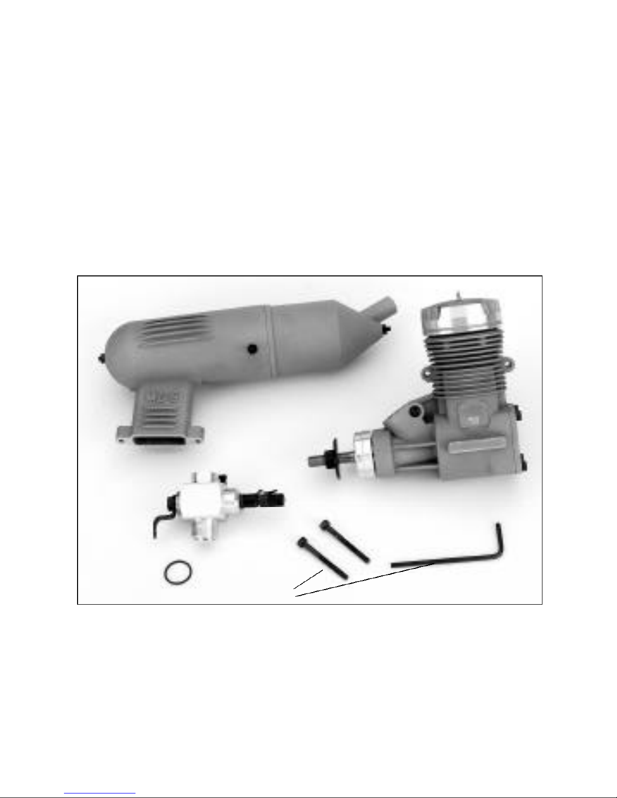
Inside the MDS engine box you should find the following items:
1. Engine
2. Aeromix™carburetor with O-rings (may be pre-installed)
3. Muffler (style may vary depending on engine)
4. Complete accessory and tool set with muffler mounting
hardware (included tools may vary with different engines)
• Instructions and warranty card
Photo 1
3
1
3
2
4
To assemble your new engine, please follow these simple steps:
Step 1A.
Note: Refer to the exploded view of the engine on the last page to
identify the parts discussed in the text.
Page 4
4
1. Remove the individual plastic bags from the box and place
them on a table or workbench. Remove the engine from its
plastic wrapper. Note: Some engines may already have the
carburetor installed, but make sure that the carb retaining bolt
is tightened.
2. Inspect the carburetor retainer to insure that the curved portion
of the carburetor retainer drawbar matches the inside wall of the
air intake port. If it does not, simply place it in position with
your finger. Next, remove the tools from their protective
wrapper. You will need the Allen wrench to tighten the
carburetor retainer. (As noted above, some engines come
with the carburetor already mounted.)
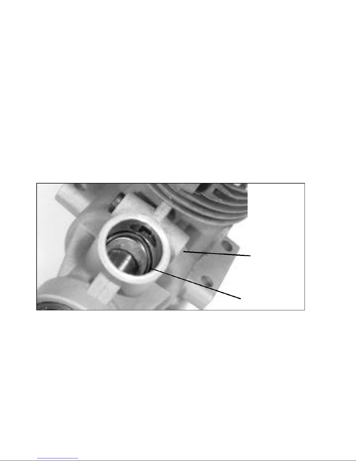
Photo 2
Carb
Retaining
Bolt
O-Ring
VERY IMPORTANT:
An improperly installed O-ring
may lead to unreliable performance.
3. Remove the O-ring from the parts bag. Install the O-ring into
the cavity of the air intake port of the crankcase, as shown in
Photo 2, making sure that the O-ring is seated evenly at the
bottom of the cavity and cannot come in contact with the
engine crankshaft. The second O-ring is a spare. Insert the
carburetor into the intake port.
Page 5

Step 1B.
4. The carburetor is correctly positioned when the throttle arm is
located on the right side of the engine when viewed from the
rear. Please note the carburetor can be rotated 180 degrees for
those applications that require the needle valve to be on the
opposite side. Tighten securely with the appropriate wrench
while applying slight pressure on the carburetor to compress the
O-ring. This will create a good, airtight seal. CAUTION: Do not
overtighten, as doing so will damage the carburetor body.
Step 2.
Break-In Procedures
5
Prior to starting your new MDS ringed or ABC engine, it’s
important that you first understand the break-in procedure for
your type of engine. Most modelers prefer to do this while the
engine is installed in the aircraft or heli. With today’s tolerances
and available metallurgy, the break-in time has been shortened to
the point that bench running is not necessary. If you’re not sure
whether your engine is ringed or ABC, simply look through the
exhaust port and move the piston until you can see the top
portion. If it’s ringed, you will see a dark metal ring approximately
1/8” from the top. If it’s ABC, the piston will be one piece and all
the same color of the piston.
Ringed Engine Break-In
Excessive heat build up during the first few runs can damage the
ring and cylinder. A very rich needle setting is required to keep the
engine cool while the ring seats. To set a “rich” mixture, lean the
high-speed needle for a good 2-cycle, then richen the high-speed
needle counter clockwise a full turn. While running rich, the
engine will create quite a bit of smoke and the exhaust will be very
oily. After a couple of tank fulls at a rich needle setting, you can
Page 6

6
begin leaning the high-speed needle a few clicks at a time for best
performance, keeping in mind that a too lean setting at any time
can damage the ring and cylinder.
ABC Engine Break-In
Breaking-in your ABC engine requires the same basic procedure as
with the Ringed engine, except for a couple of minor differences.
The first couple of runs should be at a slightly rich setting, close to
normal operating temperatures. Heat helps the piston seat in the
liner. Also, the time involved is shorter; most ABC engines can be
fully broken-in within 3 or 4 flights at a slightly rich setting.
Step 2A. Muffler Mounting
Remove the muffler from the plastic bag. The muffler mounting
bolts are located in the tool set, as are the tools to mount
the muffler.
Step 2B. Fuel Tank Placement
The location of the fuel tank can greatly affect the operation of
any engine. Whether mounting the engine on a test stand or in
your model, we suggest that you position the tank as close to the
engine as possible. The center line of the fuel tank should be as
close to level with the engine flange mounts as possible
(See diagram on next page).
Page 7

Step 2C. Propeller Selection and Installation
Please refer to the propeller selection chart below to determine the
proper size and pitch for break-in applicable to your engine size.
7
IMPORTANT: Prior to installation, be sure to balance the prop.
Unbalanced props are not only dangerous to operate, but can
lead to premature parts failure on both the engine and model.
Tightly secure the prop. Remember to inspect the prop
thoroughly for any nicks or signs of fatigue which can lead to
prop failure.
Engine Recommended Propeller Sizes
.18 FS Pro 7 x 4
7 x 6 — Break-in
8 x 4
8 x 5
.28 FS Pro 9 x 5 — Break-in
10 x 5
.38 FS Pro 9 x 6.5
10 x 5 — Break-in
10 x 6
.40 FS-1 Pro 9 x 6.5
10 x 6 — Break-in
10 x 7
.48 FS Pro 10 x 6
10 x 7 — Break-in
11 x 7
Engine Recommended Propeller Sizes
.58 FS Pro 11 x 7 — Break-in
11 x 8
11 x 9
11 x 10
.68 FS Pro 11 x 7
11 x 8 — Break-in
12 x 6
.78 FS Pro Ring 12 x 6
12 x 8 — Break-in
13 x 8
1.48 FS Pro Ring 15 x 10
16 x 8 — Break-in
16 x 10
17 x 8
17 x 10
Page 8

8
Step 2E. Starting the Engine
To start the engine, you need the following items:
• We recommend a high-quality, 2-cycle fuel containing 10–15%
nitromethane, such as Hangar 9 Aeroblend, Cool Power
or Powermaster fuels.
• Fuel pump
• A chicken stick, such as Hangar 9 Start Stick,
or electric engine starter
• Glow driver
Note: If this is the first time you’ve run a model engine, we
suggest that you get someone with experience to help. Your local
hobby dealer may be able to help or put you in touch with an
experienced modeler who would be willing to help you.
Presetting the High-Speed Needle Valve:
1. Fill the tank with the recommended fuel.
2. Connect the fuel line to the carburetor and the vent line to the
muffler pressure nipple.
3. Turn the high-speed needle clockwise until you feel a slight
resistance. This closes the needle valve completely.
4. Now, turn the high-speed needle counterclockwise a total of 21⁄2
turns. This should be a good place to start and will give a rich
full throttle setting.
Presetting the Low-Speed Needle Valve
1. Close the throttle barrel and screw the low-speed needle in until
resistance is felt. This closes the low-speed needle. Now open
(counterclockwise) the low-speed needle 21⁄2 turns. This will give
a slightly rich initial idle setting.
2. Open the throttle barrel to the full throttle position.
3. Place your finger on the carburetor opening (make sure
the glow plug battery is not connected) and rotate the
propeller counterclockwise several times or until you see fuel
flowing up to the carburetor through the fuel tubing.
4. Reduce the throttle to idle (1/16” opening in throttle barrel).
Page 9

5. Connect the glow plug battery to the glow plug at this time.
6. Using the chicken stick, turn the propeller counterclockwise
through the
compression stroke of
the engine. If the engine
has fuel and a good glow
plug, you should feel a
pronounced bump
against this movement.
When you feel the
bump, give a quick flip
to the chicken stick
(counterclockwise) and
the engine should start.
9
If it doesn’t start, repeat
the procedure.
If you use an electric starter, be sure you pull the propeller through
a complete compression cycle by hand (without glow plug battery
attached) without feeling a heavy resistance to this action (a sign
the engine is flooded). Only then should you attempt to start the
engine with the electric starter. Failure to do so can result in damage to your engine, which isn’t covered under warranty.
Allow the started engine to warm up for about 30 seconds at idle,
then advance it to full throttle. Turn the high-speed needle clockwise until you have the engine running in a slightly rich setting.
When the engine is running smoothly, disconnect the glow plug
battery. Allow the engine to run two full tanks of fuel at this slightly rich setting.
Page 10

1 0
Step 3. Low-Speed Needle Settings
The Pinch Test
You may find it necessary to make low-speed needle adjustments
for your particular application. The low-speed needle is located on
the throttle arm side of the carburetor and requires a small screwdriver to make adjustments. It’s best to tune the low-speed needle
after setting the high-speed needle.
When you have achieved the proper high-speed setting
(running slightly rich), idle the engine and pinch the fuel line with
your fingers at the fuel inlet of the carburetor. If the engine dies
immediatedly without increasing in rpm, the low setting
in too lean. To correct, back out the low-speed needle 1/2 turn
and repeat the process. When the low-speed needle is adjusted
correctly for idle, the engine rpms should increase 200–300 rpms
when the fuel line is pinched, then the engine should die. If the
Page 11

1 1
engine rpm increases more than 200–300 rpm, the low-speed
needle is too rich. To adjust, screw in the needle to 1/16 of a turn
and re-test. To achieve the correct setting, always adjust the needle
a few clicks at a time.
After you’ve attained the correct needle settings, the engine will
have a very quick throttle response from idle to full throttle, and
throughout the mid-range. Be sure to always run the high-speed
needle so that the engine is slightly rich at full throttle.
Troubleshooting
Note: If the engine quits in flight or runs lean after ground set-up,
review step 1A of this manual refering to the carb O-ring. If the
O-ring is improperly seated or installed, the engine will leak air and
may repeatedly run lean.
Step 4. Engine Care
Fuel
Always use clean, fresh fuel. Because dirt is the number one
enemy of any engine, we highly recommend the use of an in-line
fuel filter, like the Hangar 9 HAN143, between the tank and the
carburetor. Also, place one between your fuel pump and the tank
filler line.
After-Run Oil
Because model fuel contains methanol, it has the property of drawing moisture from the atmosphere. Exposure to moisture can cause
corrosion to such vital engine parts as the bearings and crankshaft.
Therefore, we strongly urge that after every flying session you drain
all fuel from the tank and then put four to five drops of after-run
oil, such as Prather Afterun or Marvel Mystery Oil, into the carburetor. Turn the prop by hand several times to insure that the afterrun oil is distributed throughout the engine.
Page 12

1 2
Prop Selection
Using the correctly sized prop to fit your particular application is
very important. Please check the included prop guidelines to
match your engine with the correct size of prop. When breaking in
the engine, please use a recommended prop size, as listed on the
chart. To fit your particular application, start with the prop you
used for break-in, and then experiment with other prop sizes to
find the one that produces the desired results without overloading
the engine.
If you plan on using a spinner, make sure the cut-outs for the
blades are deep enough to prevent any contact between the spinner and the prop blades. This will prevent any possibility of the
spinner cutting into the propeller blade and weakening it.
Glow Plug
Your MDS engine comes complete with a long reach glow plug
with idle bar. These plugs are designed for break-in only, and it’s
common for these plugs to burn out within several runs of the
engine. Their use should provide you with quick starts and a reliable idle during the break-in process. The stock break-in MDS glow
plug may be replaced with Hangar 9’s economy plug (HAN3005) or
2-cycle performance plug (HAN3000).
Do not dismantle the engine unnecessarily, as doing so can cause
damage to the precision fit parts, such as the piston and sleeve. If
it’s necessary to clean the interior of the engine (such as after a
crash), remove only the muffler, carburetor, cylinder head and
backplate. You should be able to clean all foreign matter from the
engine without disturbing the fit of the precision parts. Any further
disassembly could result in voiding the manufacturer’s warranty.
Periodically remove the muffler and inspect the piston through the
Page 13

exhaust port. Also, make sure the engine has adequate air flow for
proper cooling.
Scale aircraft cowlings may look good, but if they restrict airflow
around the engine, they can do a great deal of harm. You need
twice as much exhaust area as intake area to provide airflow for
your enclosed engine.
Step 5.
MDS Safety Instructions and Warnings
See the enclosed safety instruction card for details.
1 3
Step 6. Service and Warranty
See the enclosed registration card for details.
(Note: The parts list for the carburetor and engine are added at the
end of these instructions.)
Page 14

1 4
Page 15

1 5
Page 16

1 6
Page 17

1 7
Page 18

1 8
Dimensions (mm) A B C D E F G H I
.18 FS Pro 25 32 11 35 63.5 77 10/32 28 3
.28 FS Pro 29 38 15 47 75 92
.38 FS Pro 31 38 15 47 77 92
.40 FS-1 36 44 17.5 51 87 110
.48 FS Pro 36 44 17.5 51 87 115
.58 FS Pro 36 44 17.5 55 94 115
.68 FS Pro 40 52 25 55 100 120
.78 FS Pro Ring 40 52 25 55 100 120
1.48 FS Pro Ring 48 58 30 60 122 148
1
/4x 28 35 3
1
/4x 28 35 3
1
/4x 28 37 3
1
/4x 28 37 3
1
/4x 28 42 3
5
/16x 24 42 4
5
/16x 24 42 4
5
/16x 24 40 4
N/A= data unavailable at this time
Page 19

1 9
Page 20

2 0
MDSMAN3 Version 1.4 5 x 6.5
 Loading...