

Page 1
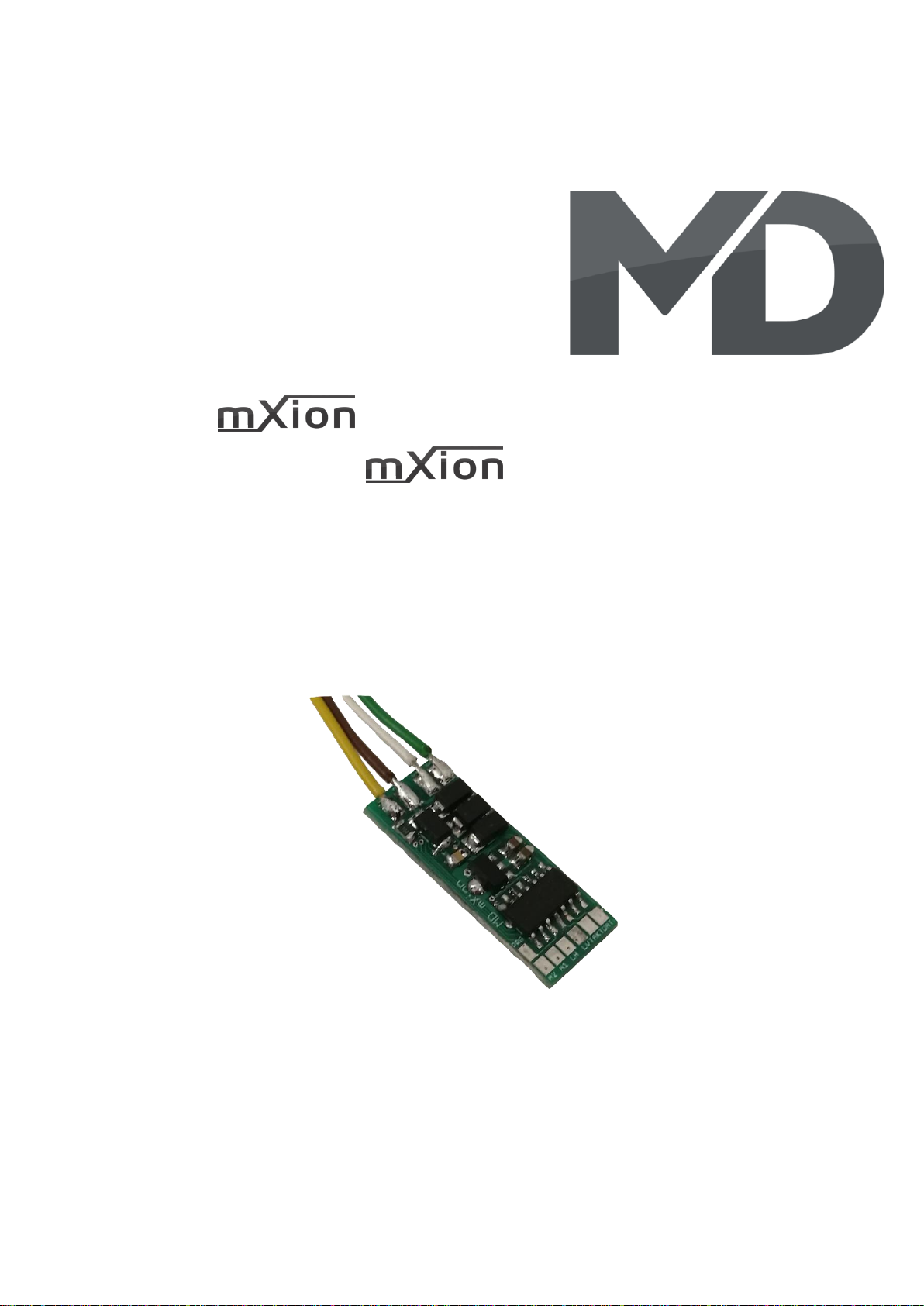
DRIVE-S Bedienungsanleitung
DRIVE-S User manual
Page 2

2 DRIVE-S
Einleitende Information Introduction
Sehr geehrte Kunden, wir empfehlen Dear customer, we strongly
die Produktdokumentation und vor recommend that you read these
allem auch die Warnhinweise vor der manuals and the warning notes
Inbetriebnahme gründlich zu lesen und thouroughly before installing and
diese zu Beachten. Das Produkt ist kein operating your device. The device
Spielzeug (15+). is not a toy (15+).
HINWEIS: Vergewissern Sie sich, ob die NOTE: Make sure that the outputs
Ausgangsspannungen zu ihrem Verbrauch- are set to appropriate value
er passen, da dieser sonst zerstört werden before hooking up any other
kann! Für Nichtbeachtung übernehmen wir device. MD can’t be responsible
keine Haftung. For any damage if this is
disregarded.
HINWEIS: Funktionsausgang A3
Page 3

3 DRIVE-S
Inhaltsverzeichnis Table of Contents
Grundlegende Informationen General information 4
Funktionsumfang Summary of functions 5
Lieferumfang Scope of supply 6
Inbetriebnahme Hook-Up 7
Anschlussbuchsen Connectors 8
Anschluss für Pufferspeicher Connection for Buffer 9
Produktbeschreibung Product description 10
Fahrstufen Steedsteps 11
Fahrkurven Speed curves 11
Rangiergang Switching speed 13
Anfahr-/Bremsverzögerung Acceleration and Deceleration 13
Abschaltbare Verzögerungszeiten Switchable delay times 13
Pendelfunktion Shuttle function 14
Pufferbetrieb Buffer operation 14
Analogbetrieb Analog operation 14
Fernlichtfunktion High beam function 15
Doppel-A Notlicht Double-A emergency light 15
Programmiersperre Programming lock 16
Programmiermöglichkeiten Programming options 16
Programmierung von binären Werten Programming binary values 17
F-Tasten-Belegung F-Key-Commands 17
Programmierung Lokadressen Programming loco adress 18
Resetfunktionen Reset functions 18
Merkmale der Funktionsausgänge Function output features 19
CV-Tabelle CV-Table 21
Technische Daten Technical data 31
Garantie, Reparatur Warranty, Service, Support 32
Hotline Hotline 33
Page 4

4 DRIVE-S
Grundlegende Informationen General information
Wir empfehlen die Anleitung gründlich We recommend studying this manual
zu lesen, bevor Sie Ihr neues Gerät in thoroughly before installing and
Betrieb nehmen. operating your new device.
Bauen Sie das Modul an einem geschützten Place the decoder in a protected location.
Platz ein. Schützen Sie es vor andauernder The unit must not be exposed to moisture.
Feuchtigkeit.
HINWEIS: Einige Funktionen sind nur mit NOTE: Some funktions are only
der neusten Firmware nutzbar, führen available with the latest firmware.
Sie daher bei Bedarf ein Update durch. Please make sure that your device
is programmed with the latest
firmware.
Page 5

5 DRIVE-S
Funktionsumfang Summary of Funktions
▪ DC/AC/DCC Betrieb DC/AC/DCC operation
▪ Für alle Spuren geeigent Z-G, pefekt für H0-Loks For all scales available Z to G, perfekt for H0
▪ Erhältlich mit div. Adaptern (NEXT, NEM, LGB) Adapter for NEM, NEXT, LGB
▪ Vollkompatibles NMRA-DCC Modul Compatible NMRA-DCC module
▪ 1.5A Motorstufe (2A Spitze) 1.5 Amps engine output (2 Amps peak)
▪ Temperatur und Überstromschutz Temperature and over current protection
▪ SUSI Bus SUSI Bus
▪ Pendelzugsteuerung direkt einstellbar Shuttle train directly configurable
▪ Superkleine Abmaße Very small module
▪ Unterschiedliche Gesch. für Vor- und Rückwärts Differend forward and backward speeds
▪ Handbremsenfunktion Hand brake function
▪ Kupplungswalzer Kupplungswalzer
▪ Insgesamt 4 Funktionsausgänge, davon: In sum, 4 function outputs with:
▪ 2 verstärkte Funktionsausgänge 2 reinforced function outputs
▪ Licht innen, Licht vorne verstärkt Light input, light front, reinforced
▪ Viele Sonder- und Zeitfunktionen einstellbar Lot of special and time functions available
▪ Taktsimulation Clock simulation
▪ 23 Lichteffekte auf allen Ausgängen 23 light effects on all outputs
▪ Funktionsausgänge dimmbar Function outputs dimmable
▪ Resetfunktionen für alle CVs Reset function for all CV values
▪ Sehr einfaches Funktionsmapping Easy function mapping
▪ 28 Funktiontasten adressierbar, 10239 Lokadressen 28 function keys programmable, 10239 loco
▪ 14, 28, 128 Fahrstufen (automatisch) 14, 28, 128 speed steps (automaticly)
▪ Vielfältige Programmiermöglichkeiten Multiple programming options
(Bitweise, CV, POM Schaltdecoder, Register) (Bitwise, CV, POM accessoire decoder, register)
▪ Keine Last bei Programmierung erforderlich Needs no programming load
▪ Freies Funktionsmapping (F0 – F28) für alle Funktion Free function mapping (F0 – F28) for all
▪ Kompatibel zu NMRA DCC und LGB® MZS (alle) Compatible to NMRA DCC and all LGB® MZS
▪ Parallele Funktionsauslösung Parallel function keying
▪ Spannungspufferanschluss für gleichmäßigen Lauf Voltage puffer connection for same run
▪ Einfaches, verständliches Funktionsmapping Simple, easy understand function mapping
▪ Viele weitere Funktionen einstellbar Lot of functions configurable
Page 6

6 DRIVE-S
Lieferumfang Scope of supply
▪ Bedienungsanleitung Manual
▪ mXion DRIVE-S mXion DRIVE-S
Je nach Ausführung anderer Schnittstellen Depending on delivering, adapters
Adapter angebracht oder komplett ohne for all kinds of plug available, e.g.:
Adapter möglich für Schnittstellen: - NEM
- NEM - NEXT
- NEXT - LGB
- LGB - and more
- uvm
Page 7

7 DRIVE-S
Inbetriebnahme Hook-Up
Bauen bzw. platzieren Sie Ihr Install your device in compliance with
Gerät sorgfältig nach den Plänen the connecting diagrams in this manual.
dieser Bedienungsanleitung. The device is protected against shorts and
Die Elektronik ist generell gegen excessive loads. However, in case of a
Kurzschlüsse oder Überlastung connection error e.g. a short this safety
gesichert, werden jedoch Kabel feature can’t work and the device will be
vertauscht oder kurzgeschlossen destroyed subsequently.
kann keine Sicherung wirken und Make sure that there is no short circuit
das Gerät wird dadurch ggf. zerstört. caused by the mounting screws or metal.
Achten Sie ebenfalls beim befestigen
darauf, dass kein Kurzschluss mit
Metallteilen entsteht.
HINWEIS: Bitte beachten Sie die NOTE: Please note the CV basic settings
CV-Grundeinstellungen im Auslieferungszustand. in the delivery state.
Page 8
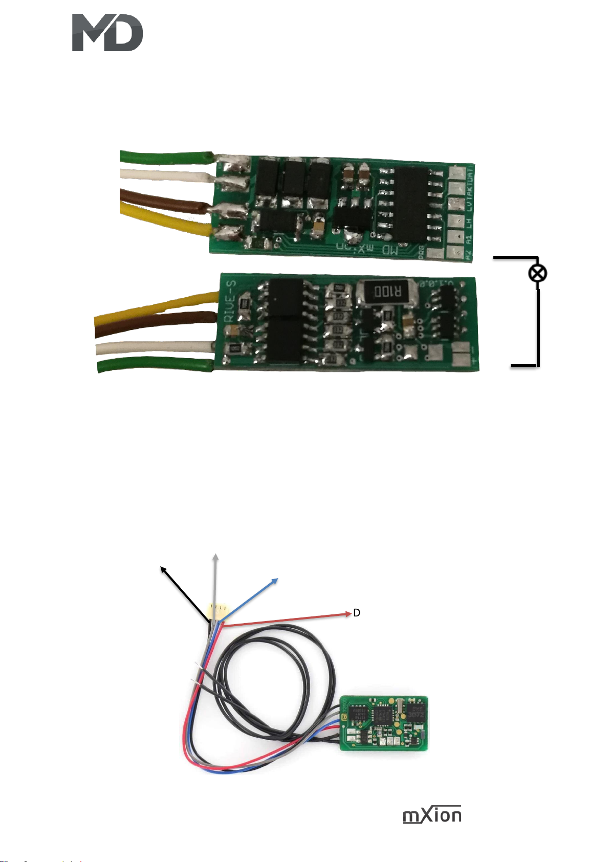
8 DRIVE-S
SUSI-Daten
SUSI-Takt
Licht vorne
Licht hinten
A1
A2
Motor+
GLEIS+
GLEISMotor-
Anschluss von SUSI-Modulen / Connection of SUSI-Modules
DEC-
DEC+
SUSI-Daten
SUSI-Takt
Anschlussbuchsen Connectors
DECDEC+
Page 9
9 DRIVE-S
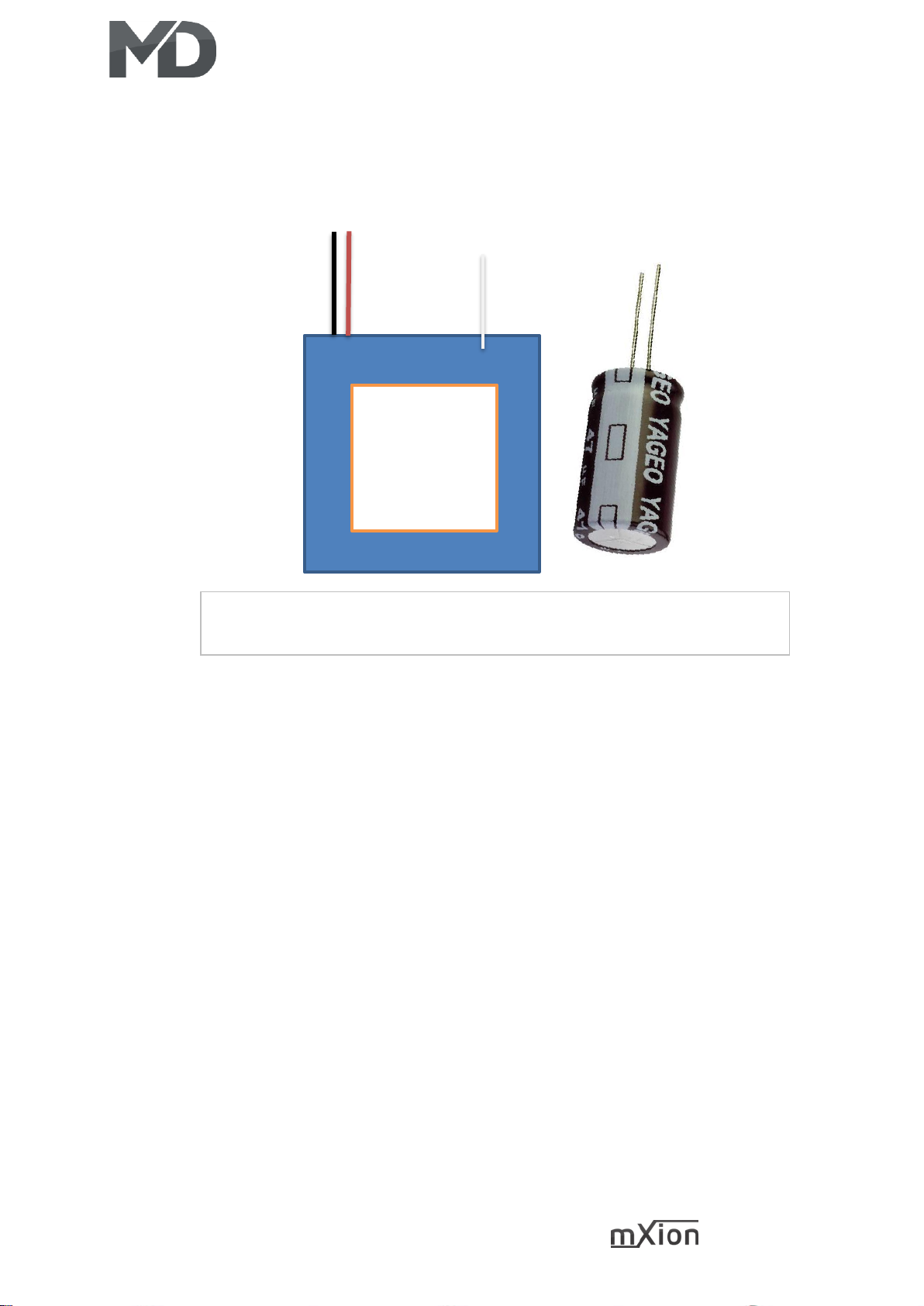
Anschluss für Pufferspeicher Connection for Buffer
Powercap ODER Kondensator (ab 2000 µF Diode/Widerstand (120 Ohm) nutzen)
Powercap or normally cap (above 2000 µF Diode/Resistor (120 Ohm) use)
Powercap
Powercap
DEC+
GND
DEC+
A1 oder A2
A1 oder A2
Page 10

10 DRIVE-S
Produktbeschreibung Product description
Der mXion DRIVE-S ist ein sehr leistungsstarker The mXion DRIVE-S is a very strong 1.5
1.5A Lokdecoder. Er kann digital und analog train decoder. he can be digital
arbeiten und bietet mit seinen 2 Funktionsausgängen and analog works and offers with its 2
und 2 Lichtausgängen ein sehr großes und function outputs and 2 light outputs
leistungsstarkes Spektrum. a very large and powerful spectrum.
Der DRIVE-S ist ideal für alle Loks von Spur Z-H0 und The DRIVE-S is ideal for all locomotives of
für alle Großbahnloks wie Spur 0,1 und G geeignet. scale Z to H0 and suitable for all large train
Bei Großbahnloks eignet der Decoder sich perfekt locomotives like scale 0, 1 and G. For large
für kleinere Loks wie die Stainz® oder die Feldbahnloks. train locomotives, the decoder is perfect for
smaller trains e.g. Stainz® or the feldbahn
Den Decoder gibt es mit div. Kabeln für alle trains. The decoder is available with various
Schnittstellen und Spurweiten nach NEM, NEXT und cables for all interfaces and gauges according
für Großbahnen mit Lötschuhen zur direkten to NEM, NEXT and for large trains with solder
Montage an LGB® Getriebe. shoes for direct mounting on LGB® gearbox.
Sound kann man einfach nachrüsten mit einem Sound can be easily retrofitted with one SUSI
SUSI-Soundmodul. Der SUSI-Bus ist als Lötkontakt sound module. The SUSI bus is as a solder
ausgeführt. contact executed.
Der Decoder hat zudem direkt die Möglichkeit ein The decoder also has the option
Rangierlicht „Doppel-A“ zu aktivieren als auch of a direct shunting light „double-A“ to
eine Fernlichtfunktionen. activate as well a high beam functions.
Zum Standardumfang gehört natürlich ein Rangiergang The standard scope of course includes a
als auch abschaltbare Verzögerungszeiten. maneuvering as well as turn-off delay times.
Im Analogbetrieb sind alle Ausgänge mit vollem In analog mode, all outputs are full
Funktionsumfang ebenfalls nutzbar. functionality also usable.
Zudem können alle Ausgänge gedimmt werden. In addition, all outputs can be dimmed.
Auch der beliebte Kupplungswalzer wird unterstützt. Also, the kupplungswalzer will be there.
Eine Taktsimulation kann an Funktionsausgängen The clock simulation is possible on all
emuliert werden. Dabei in Sonderfunktion die function outputs, defined in special
Taktsimulation wählen, über CV 116 kann eine function mode. Over CV 116, it is
Korrektur an die Lok angepasst werden. possible to correct the clock time.
Page 11

11 DRIVE-S
Fahrstufen Speedsteps
Die Fahrstufen (Anzahl, Geschwindigkeit The speed steps (speed increments
zwischen Stillstand und max. Geschwindigkeit) between standstill and maximum speed)
können zwischen 14, 28 und 128 gewählt werden. may be set to 14, 28 and 128. CV 29 Bit 1
Dabei muss zwischen 14 und 28 Fahrstufen must be set to 0 for 14 and to 1 for
mittels Einstellung (CV 29, Bit 1) unterscheiden 28/128 speed steps. The difference between
werden. 128 Fahrstufen werden automatisch 28 and 128 are detected automatically.
erkannt. LGB MZS I+II unterstützen nur 14 LGB MTS I and II require 14 speed steps.
Fahrstufen. Die Standardeinstellung beträgt The standard setting is 28/128 speed steps.
28/128 Fahrstufen.
Fahrkurven Speed curves
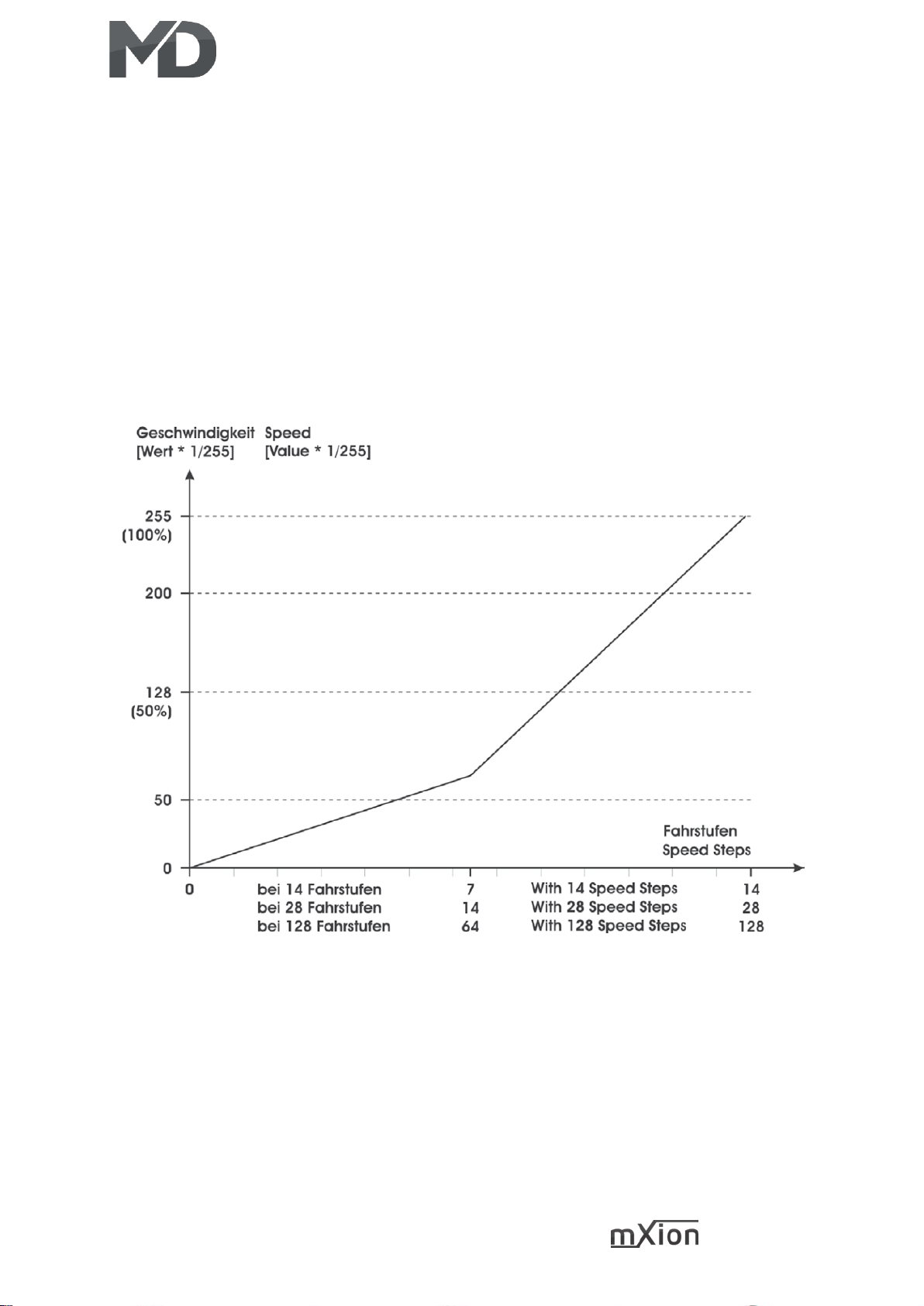
Das Fahrverhalten kann mittels Fahrkurve The speed characteristic of the locomotive
beeinflusst werden. Wahlweise können eine is defined by the speed curve. You may
lineare Fahrkurve oder eine frei programmierbare choose between a linear speed curve or a
Fahrkurve verwendet werden. Die lineare Fahrkurve freely programmable speed curve. The
wird mit 3 Werten eingestellt. Diese Fahrkurve ist linear speed curve is defined by 3 CVs.
deutlich einfacher einzustellen und daher auch The standard speed curve is linear because
standardmäßig aktiviert (siehe CV 29). Die it is easier to be set (CV 29). The start voltage
Anfahrspannung (CV 2) legt fest, mit welcher (CV 2) defines the driving voltage of speed
Spannung die Lok in der ersten Fahrstufe anfährt. step 1. The smaller the the slower the
Je kleiner der Wert, desto langsamer fährt die Lok an. locomotive starts driving. If the PI-Load
Wenn bei abgeschalteter Lastregelung die in Stufe 1 control is „off“ and the locomotive does not
nicht anfährt, sollte dieser Wert erhöht werden. move with speed step 1, the start voltage
Die maximale Geschwindigkeit (CV 5) kann durch should be increased. The maximum speed
das programmieren von kleineren Werten reduziert (CV 5) my be reduced by inserting smaller
werden. Verringert man diesen Wert, so ändert sich values. Decreasing CV 5 alters all speeds in a
die Geschwindigkeit aller Fahrstufen linear mit. Die linear way. The mid-speed (CV 6) influences
mittlere Geschwindigkeit (CV 6) beeinflusst die the linearity of the speed curve. In the case
Linearität der Fahrkurve. Wenn in CV 6 der halbe CV 6 is half of the value of CV 5 (max. seep),
Wert von CV 5 steht, sind alle Fahrstufen all speed steps are distributed equally.
gleichmäßig verteilt. Ist CV 6 kleiner als die Hälfte In case CV 6 is smaller than half the value
von CV 5, werden die unteren Fahrstufen gestreckt. of CV 5, the lower speed steps will be
Die Lok fährt dann bei mittlerer Geschwindigkeit stretched. The locomotive will drive
Page 12
12 DRIVE-S
langsamer, es ergibt sich ein ausgedehnter slower at mid-speed; the slow speed range
Langsamfahrbereich, optimal zum Rangieren. will be extended (ideal for shunting).
Alternativ kann über CV 67 – CV 94 die Fahrkurve As an alternative you may program the
in 28 Stufen frei programmiert werden. Die speed curve individually in 28 steps
programmierte Fahrkurve wird mit CV 29 Bit 4 (CV 67 – 94). This speed curve is activated
aktiviert. Bei Nutzung der Fahrkurve haben by CV 29 bit 4. In this case the CVs 2,5,6 are
CV 2, 5 und CV 6 keine Funktion mehr. deactivated!
Page 13

13 DRIVE-S
Rangiergang Switching speed
Für ein deutlich feineres Fahrgefühl beim The maximum speed is reduced by half
Rangieren kann über eine frei programmierbare to facilitate a more effective driving
Funktionstaste ein Rangiergang aktiviert werden characteristic during switching. This feature
(CV 100). Dabei wird die Fahrgeschwindigkeit, may be set to any programmable function
unabhängig von der Fahrstufe, halbiert. Die key in CV 100. With CV 100 = 64 the function
Nummer der F-Taste wird direkt in CV 100 is off.
programmiert. Mit CV 100 = 64 wird die Note: Programm the function to the key
Funktion abgeschaltet. Tipp: Legen Sie den for the „double-A” shunting light.
Wert auf die Funktionstaste für „Doppel-A“
Rangierlicht.
Anfahr-/Bremsverzögerung Acceleration and Deceleration
Eine Zeitverzögerung beim Anfahren und The acceleration and deceleration
Bremsen kann mit CV 3 (Beschleunigung) characteristic may be defined with CV 3
und CV 4 (Abbremsen) eingestellt werden. (acceleration) and CV 4 (deceleration).
Die Verzögerungszeit vom Stand bis zur The CV setting represents the time the
Höchstgeschwindigkeit (oder umgekehrt) decoder takes to reach a newly selected
beträgt je gezähltem Wert 1 genau speed. The values in CV 3 and CV 4 are time
0,5 sek. Multiplizieren Sie die gewünschte units. One unit equals 0.5 seconds. To get
Verzögerungszeit mit 2 und programmieren your intended acceleration/deceleration
Sie diesen Wert in die jeweilige CV. time by 2 and programm this in CV 3 and CV 4.
Abschaltbare Verzögerungszeiten Switchable delay times
Die programmierten Zeitwerte von CV 3, 4 The settings of CV 3, 4 can be disabled
können mittels frei programmierbarer by a function key that is stored in CV 101.
Funktionstaste abgeschaltet werden (CV 101).
Page 14

14 DRIVE-S
Pendelfunktion Shuttle function
Für automatische Abläufe kann eine For automatic processes, a
Pendelfunktion aktiviert werden pendulum function can be activated
(CV 103 > 0). CV 103 definiert zugleich (CV 103 > 0). CV 103 defines at the same
die Fahrdauer in Sekunden. CV 104 die time the driving time in seconds. CV 104
Haltezeit in Sekunden. CV 102 die the speed. Activation is from CV30 with
Geschwindigkeit. Über CV30 ist es aktivierbar. f-key. Also possible to activate permanent.
Auch dauerhaft kann die Pendelfunktion angeschaltet
werden. Die Aktivierung erfolgt über F-Tasten.
Pufferbetrieb Buffer operation
Wird über „BC“ ein Pufferspeicher betrieben, If a power buffer is connected to “BC”
kann über CV 47 die Puffernachlaufzeit CV 47 sets the buffering time. Digital
eingestellt werden. Im Digitalbetrieb muss operation with a buffer requires analog
mit Puffer der Analogbetrieb (CV 29, Bit 2) operation to be deactivated with CV 29 bit 2.
gesperrt werden. Schließen Sie Puffer an Connect a buffer to a output (A1 – A2) and
einen beliebigen Ausgang (A1-A2) an und activate special function „BC“.
wählen Sie die Sonderfunktion „BC“.
Analogbetrieb Analog operation
Im Auslieferungszustand ist der Analogbetrieb The factory default setting allows the analog
gestattet. Die Lichtausgänge sind im Analogbetrieb operation. The light outputs are constantly
immer richtungsabhängig an. Die on and working dependet of the driving
Funktionsausgänge (A1 – A2) können über CV 13 direction. The function outputs (A1 – A2) may
aktiviert werden. Alle Einstellungen der Ausgänge be activated separately for analog operation
(Dimming Lichteffekte, etc…) ist weiterhin nutzbar. in CV 13. Settings for flashing, dimming, etc..
works as well.
Page 15

15 DRIVE-S
Fernlichtfunktion High beam function
Über CV 97 kann die Funktionstaste angegeben The function key can be specified via CV 97
werden, womit die Fernlichtfunktion geschaltet be with which the high beam function
wird. Die Beleuchtung dimmt sich dann um 50 % switched becomes. The lighting dims then by
runter (Fernlicht deaktiv). Die F-Taste ist frei 50 % down (high beam deactivated). The
vergebbar. Natürlich ist die Funktion auch F-Key is free assignable. Of course the
komplett deaktivierbar. function is too completely deactivatable.
Doppel-A Notlicht Double-A emergency light
Über CV 110 kann die Funktionstaste angegeben The function key can be specified via CV 110
womit das Notlicht (Doppel-A) geschaltet wird. with which the emergency light (double-A) is
Beim Schweizer-Mapping ist die Belegung switched. When Swiss-Mapping is the
der kompletten Ausgänge vorgegeben, das occupancy the complete outputs, the
Notlicht ist dabei 3x rot der Spitzbeleuchtung. emergency light is 3x red of the spotlight.
Wenn kein Schweizer-Mapping genutzt wird, If no Swiss-Mapping is used, when emergency
leuchten beim Notlicht alle Lichtausgänge, light illuminate all the light outputs, so light
also Licht vorne + Licht hinten auf, unabhängig forward + light on the back, independent from
von der Fahrtrichtung. Dieser Effekt ist dann the direction of travel. This effect is then
sinnvoll, wenn das Fahrzeug keine roten useful if the vehicle is not red taillights owns.
Rückleuchten besitzt. Wenn rote Rückleuchten When red taillights are present, but no
vorhanden sind, aber kein Schweizer-Mapping Swiss-Mapping is needed, the taillights
benötigt wird, können die Rückleuchten optionally via other function outputs be
optional über andere Funktionsausgänge operated, and these too on the key F0 or
betrieben werden, und diese ebenfalls other F-Key as well as the corresponding
auf Taste F0 oder andere F-Taste condition be programmed. Then you can be
sowie die entsprechende Bedingung turned off separately. Of course the
programmiert werden. Dann können Sie function is too completely deactivatable.
separat ausgeschaltet werden. Natürlich ist die
Funktion auch komplett deaktivierbar.
Page 16

16 DRIVE-S
Programmiersperre Programming lock
Um versehentliches Programmieren To prevent accidental programming to
zu verhindern bieten CV 15/16 eine prevent CV 15/16 one programming
Programmiersperre. Nur wenn lock. Only if CV 15 = CV 16 is a
CV 15 = CV 16 ist eine Programmierung programming possible. Changing CV 16
möglich. Beim Ändern von CV 16 ändert sich changes automatically also CV 15.
automatisch auch CV 15. Mit CV 7 = 16 kann With CV 7 = 16 can the programming
die Programmiersperre zurückgesetzt werden. lock reset.
STANDARTWERT CV 15/16 = 205 STANDARD VALUE CV 15/16 = 205
Programmiermöglichkeiten Programming options
Dieser Decoder unterstützt die folgenden This decoder supports the following
Porgrammierarten: Bitweise, POM, Register programming types: bitwise, POM and
CV lesen & schreiben. CV read & write and register-mode.
Es wird keine zusätzliche Last zur Programmierung There will be no extra load for
benötigt. programming.
Im POM (Programmierung auf dem Hauptgleis) In POM (programming on maintrack) the
wird ebenfalls die Programmiersperre unterstützt. programming lock is also supported.
Der Decoder kann zudem auf dem Hauptgleis The decoder can also be on the main
programmiert werden, ohne das andere Decoder track programmed without the other
beeinflusst werden. Somit muss bei Programmierung decoder to be influenced. Thus, when
kein Ausbau des Decoders erfolgen. programming the decoder can not be
removed.
HINWEIS: Um POM zu nutzen ohne andere NOTE: To use POM without others
Decoder zu beeinflussen muss Ihre Digitalzentrale decoder must affect your digital center
POM an spezifische Decoderadresse unterstützten . POM to specific decoder adresses.
Page 17

17 DRIVE-S
Programmierung von binären Werten Programming binary values
Einige CV’s (bspw. 29) bestehen aus Some CV’s (e.g. 29) consist of
sogenannten binären Werten. Das so-called binary values. The
bedeutet, dass mehrere Einstellungen in means that several settings
einem Wert zusammengefasst werden. in a value. Each function has a bit
Jede Funktion hat eine Bitstelle und position and a value. For
eine Wertigkeit. Zur Programmierung programming such a CV must have
einer solchen CV müssen alle Wertigkeiten all the significances can be added. A
addiert werden. Eine deaktivierte Funktion disabled function has always the
hat immer die Wertigkeit 0. value 0.
BEISPIEL: Sie wollen 28 Fahrstufen, EXAMPLE: You want 28 drive steps
lange Lokadresse programmieren. and long loco address. To do this,
Dazu müssen Sie in CV 29 den Wert you must set the value in CV 29
2 + 32 = 34 programmieren. 2 + 32 = 34 programmed.
F-Tasten-Belegung F-Key-Commands
F0 = Licht vorne/hinten/innen (CV50,55) F0 = light front/back/middle (CV50,55)
F12 = Handbremse (CV96) F12 = Handbrake (CV96)
F13 = Doppel-A Rangierlicht (CV110) F13 = Double-A shunt light (CV110)
F14 = Fernlicht (CV97) F14 = Fear light (CV97)
F15 = Rangiergang (CV100) F15 = Shunting (CV100)
F16 = Abschaltbare Verzögerung (CV101) F16 = Switch-off delay time (CV101)
F26 = Lichtunterdrückung vorne (CV31) F26 = Light press front (CV31)
F27 = Lichtunterdrückung hinten (CV32) F27 = Light press back (CV32)
F28 = Pendelfunktion (CV30) F28 = Pendula function (CV30)
Page 18

18 DRIVE-S
Programmierung Lokadressen Programming loco adress
Lokadresse bis 127 werden direkt in CV 1 Locomotives up to 127 are programmed
eingetragen. Hierzu muss außerdem directly to CV 1. For this, you need CV 29
CV 29 – Bit 5 „aus“ sein (wird autom. gesetzt). Bit 5 „off“ (will set automaticly).
Wenn größere Adressen genutzt werden If larger addresses are used, CV 29 – Bit 5
sollen, muss CV 29 – Bit 5 „an“ sein (automatisch must be „on“ (automaticly if change CV
wenn CV 17/18 geändert wird). Die 17/18). The address is now in CV 17
Adresse wird nun in CV 17 und CV 18 and CV 18 stored. The address is then
gespeichert. Die Adresse wird dann wie like follows (e.g. loco address 3000):
folgt berechnet (bspw. Lokadresse 3000):
3000 / 256 = 11,72; CV 17 ist 192 + 11 = 203. 3000 / 256 = 11,72; CV 17 is 192 + 11 = 203.
3000 – (11 x 256) = 189; CV 18 ist also 189. 3000 – (11 x 256) = 189; CV 18 is then 189.
Resetfunktionen Reset functions
Über CV 7 kann der Decoder zurückgesetzt The decoder can be reset via CV 7. Various
werden. Dazu sind div. Bereiche nutzbar. areas can be used for this purpose.
Schreiben mit folgenden Werten: Write with the following values:
• 11 (Grundfunktionen) 11 (basic functions)
• 16 (Programmiersperre CV 15/16) 16 (programming lock CV 15/16)
• 22 (Lichtfunktionen CV 50 – CV 59) 22 (light functions CV 50 – CV 59)
• 33 (Funktionsausgänge 1-2) 33 (function outputs 1-2)
• 44 (Motorsteuerung) 44 (engine control)
• 66 (Fahrkuve CV 67 – CV 94) 66 (drive courve CV 67 – CV 94)
Page 19
19 DRIVE-S
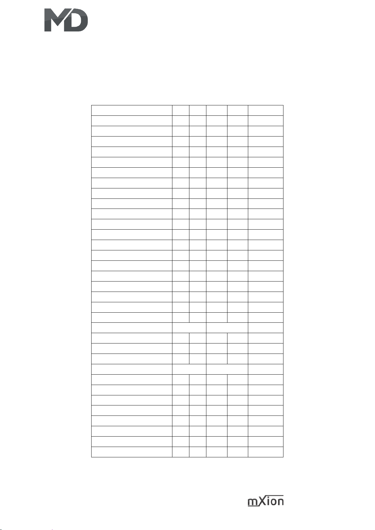
Merkmale der Funktionsausgänge Function output features
Funktion
A1
A2
LV
LH
Zeitwert
An/Aus
X X X X
Deaktiviert
X X X X
Dauer-An
X X X X
Nur vorwärts
X X X X
Nur Rückwärts
X X X X
Nur Stand
X X X X
Nur Fahrt
X X X X
Zeitfunktion sym.
X X X X X
Zeitfunktion asym. kurz
X X X X X
Zeitfunktion asym. lang
X X X X X
Monoflop
X X X X X
Einschaltverzögerung
X X X X X
Kesselfeuer
X X X X
TV flackern
X X X X
Fotograf/Blitzlicht
X X X X X
Schweißlicht
X X X X
Petroleum flackern
X X X X
Leuchtstoffröhrenstart
X X X X
Defekte Neonröhre
X X X X
Sodium/Natriumlampe
X X X X
Paarw. Wechselblinker
X X X
US strobelight
X X X X
US double strobelight
X X X X
US marslight
X X X X X
US ditchlight
X X X
Auf-/Abdimmen
X X X X
Invers
X X X X
Auto. Zurückschaltung
X
Dimmbar
X X X X
Servo
Buffercontrol
X X X X
Clocksimulation
X
Gepulster Verdampfer
X
Page 20
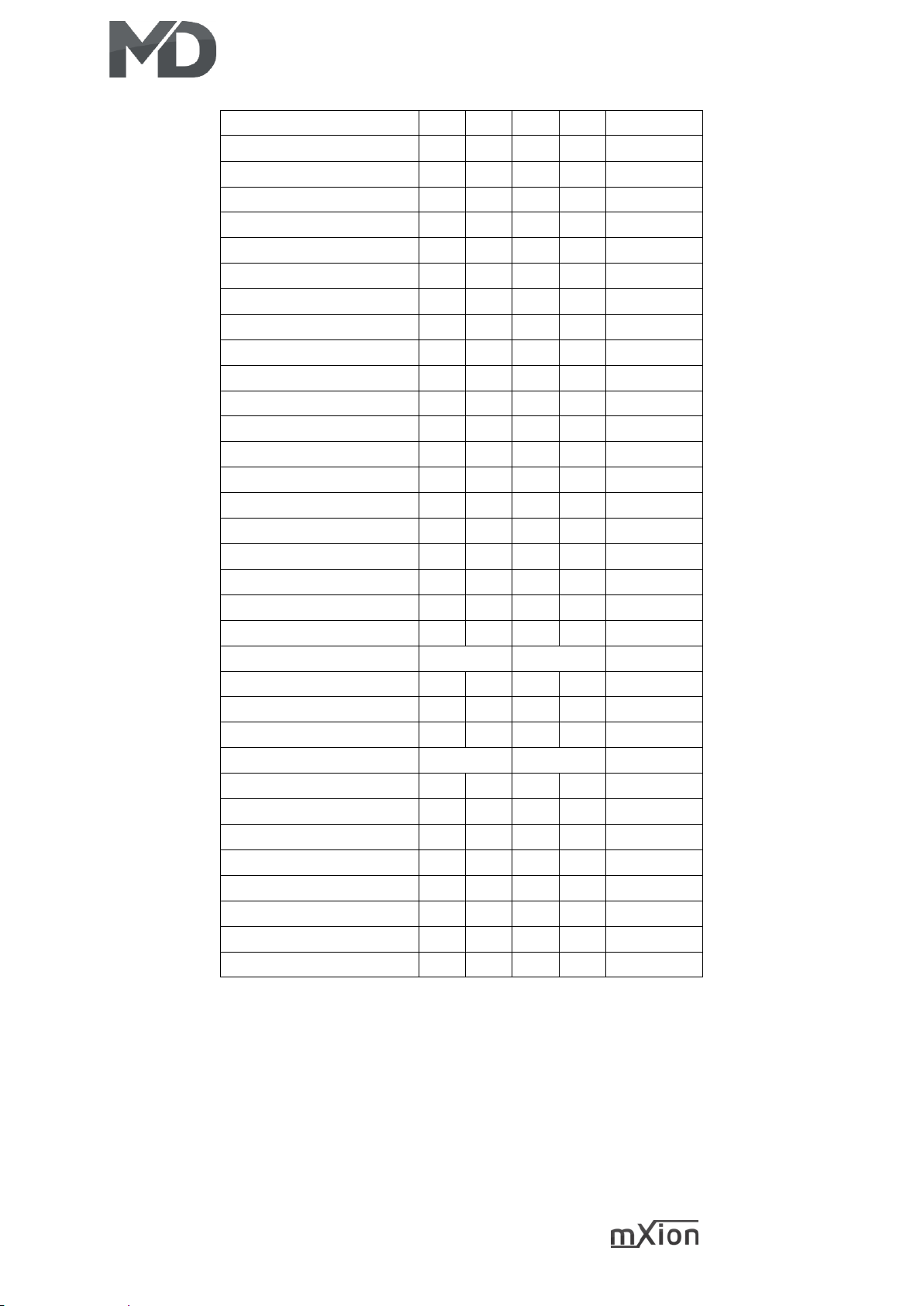
20 DRIVE-S
Funktion
A1
A2
LF
LB
Timevalue
On/Off
X X X X
Deactivated
X X X X
Permanent-On
X X X X
Forwards only
X X X X
Backwards only
X X X X
Standing only
X X X X
Driving only
X X X X
Timer sym. flash
X X X X X
Timer asym. short
X X X X X
Timer asym. long
X X X X X
Monoflop
X X X X X
Switch on delay
X X X X X
Firebox
X X X X
TV flickering
X X X X
Photographer flash
X X X X X
Welding light
X X X X
Petroleum flickering
X X X X
Flourescent tube
X X X X
Flourescent tube defect
X X X X
Sodium lamp
X X X X
Pairwise alternating
X X X
US strobelight
X X X X
US double strobelight
X X X X
US marslight
X X X X X
US ditchlight
X X X
Fade in/out
X X X X
Invers
X X X X
Autom. switch back
X
Dimmable
X X X X
Servo
Buffer control
X X X X
Clock simulation
X
Pulsed smoke unit
X
Page 21
21 DRIVE-S
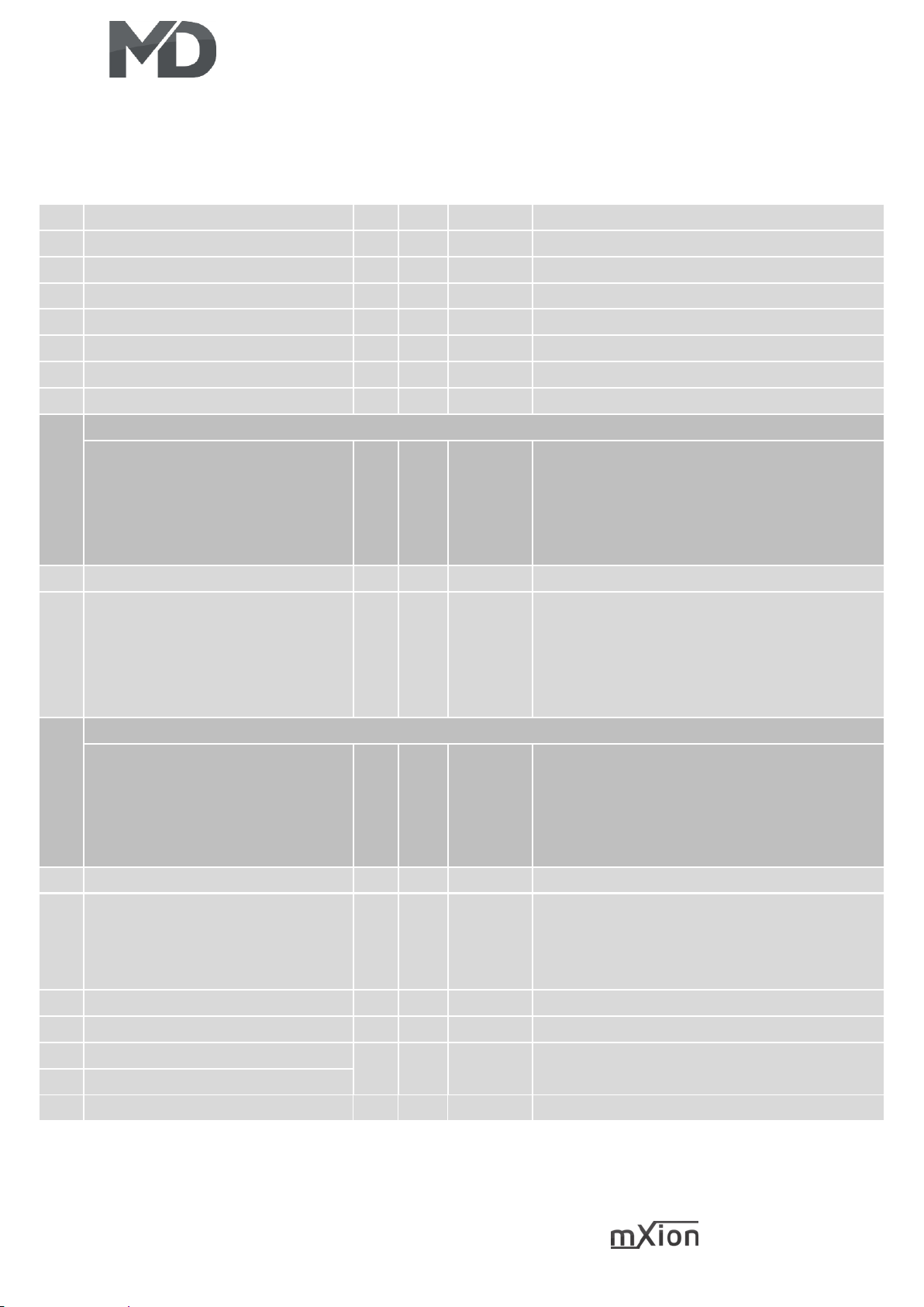
CV-Tabelle
S = Standard, A = Analogbetrieb nutzbar
CV
Beschreibung
S A Bereich
Bemerkung
1
Lokadresse
3 1 – 127
wenn CV 29 Bit 5 = 0 (automatisch)
2
Anfahrspannung
5 0 – 255
CV2 x (1/255 Gleisspannung)
3
Anfahrverzögerung
10 √ 0 – 255
CV3 x 2ms x (1/255 Gleisspannung)
4
Bremsverzögerung
10 √ 0 – 255
CV4 x 2ms x (1/255 Gleisspannung)
5
Maximale Fahrgeschwindigkeit
200 √ 0 – 255
CV5 x (1/255 Gleisspannung)
6
Mittlere Fahrgeschwindigkeit
100 0 – 255
CV6 x (1/255 Gleisspannung)
7
Softwareversion
– –
nur lesbar (10 = 1.0)
7
Decoder-Resetfunktionen
6 Resetbereiche wählbar
11
16
22
33
44
Grundfunktionen (CV 1,11-13,17-19,29-119)
Programmiersperre (CV 15/16)
Lichtausgänge (CV50-59)
Funktionsausgänge 1 – 8 (CV 1x0-1x4)
Motorfunktionen (CV2-6,9,10,54-25,60-66)
8
Herstellerkennung
160 –
nur lesbar
9
Motorfrequenz
0
√
0 – 4
0 = 16 kHz
1 = 2 kHz
2 = 250 Hz
3 = 60 Hz
4 = 100 kHz
7+8
Registerprogramiermodus
Reg8 = CV-Adresse
Reg7 = CV-Wert
CV 7/8 behalten dabei ihren Wert
CV 8 erst mit Zieladresse beschreiben, dann
CV 7 mit Wert beschreiben oder auslesen
(bspw: CV 49 soll 3 haben)
➔ CV 8 = 49, CV 7 = 3 senden
11
Analogwechsel
30 √ 30 – 255
1ms je Wert
13
Funktion der Funktionsausgänge
im Analogbetrieb
(An, wenn Funktionswert
gesetzt)
3
√
0 – 255
Werte der gewünschten Funktion addieren!
A1 = 1, A2 = 2
15
Programmiersperre (Schlüssel)
205 0 – 255
Zum Sperren nur diesen ändern
16
Programmiersperre (Schloss)
205 0 – 255
Änderung hier ändert CV 15
17
Lange Lokadresse (hoch)
128 L 1 –
10239
Aktiv nur wenn CV 29 Bit 5 = 1
(automatisch wenn CV 17/18 geändert)
18
Lange Lokadresse (tief)
19
Multitraktionsadresse
0 L 1 – 127
Lokadresse für Mehrfachtraktion
Page 22
22 DRIVE-S
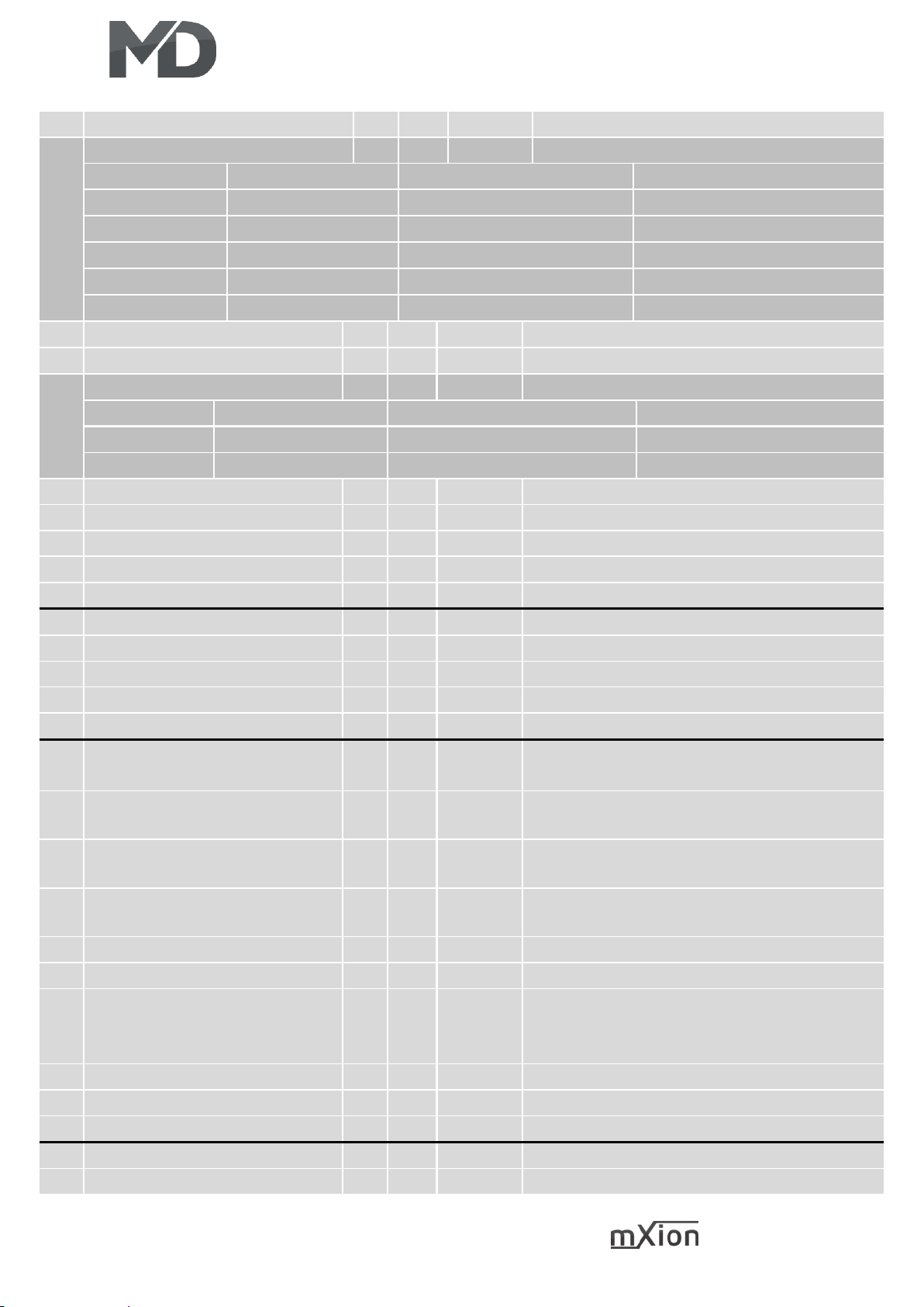
CV
Beschreibung
S A Bereich
Bemerkung
29
NMRA Konfiguration
6 √
bitweise Programmierung
Bit
Wert
AUS (Wert 0)
AN
0
1
Normale Richtung
Inverse Richtung
1
2
14 Fahrstufen
28/128 Fahrstufen
2
4
nur Digitalbetrieb
Digital + Analogbetrieb
4
16
interne Fahrkurve
program. Fahrkurve (CV67-94)
5
32
kurze Lokadresse (CV 1)
lange Lokadresse (CV 17/18)
30
Schaltbefehl Pendelbetrieb
28 √
siehe Anhang 1
47
Puffernachlaufzeit
5 √ 1 – 255
1 sek. / Wert
49
MD Konfiguration
23 √
bitweise Programmierung
Bit
Wert
AUS (Wert 0)
AN
5
32
Lightausgänge normale
Lichtausgänge invers
7
128
Digital -> Analog normal
Digitalrichtung beibehalten
50
LV Schaltbefehlszuordnung
0
siehe Anhang 1
51
LV Dimmwert
15 √
siehe Anhang 2, eingestellt auf 5V
52
LV Bedingung
1 √
siehe Anhang 3
53
LV Sonderfunktion
64 √
siehe Anhang 4
54
LV Zeitwert für Sonderfunktion
10 √ 1 – 255
Zeitbasis 0,1 sek. pro Wert
55
LH Schaltbefehlszuordnung
0
siehe Anhang 1
56
LH Dimmwert
15 √
siehe Anhang 2, eingestellt auf 5V
57
LH Bedingung
2 √
siehe Anhang 3
58
LH Sonderfunktion
64 √
siehe Anhang 4
59
LH Zeitwert für Sonderfunktion
10 √ 1 – 255
Zeitbasis 0,1 sek. pro Wert
63
Monoflop Funktion für CV96
0 0 – 255
0 = dauerhaft normale Funktion
1 – 255 Abschaltung nach CV63 * 1 sek.
66
Vorwärts-Trimm
255 √ 1 – 255
Untersetzung der max. Geschwindigkeit
vorwärts (CV66 * CV5 / 255)
67-
94
Frei programmierbare
Fahrkurve
√ 1 – 255
siehe Anhang 6
95
Rückwärts-Trimm
255 √ 1 – 255
Untersetzung der max. Geschwindigkeit
rückwärts (CV95 * CV5 / 255)
96
Handbremse Schaltbefehl
12
siehe Anhang 1
97
Fernlicht Schaltbefehl
14
siehe Anhang 1, Anhang 4
98
Zufallsgenerator
0 √ 0 – 255
Werte der gewünschten Funktion addieren!
0 = deaktiv
A1 = 1, A2 = 2
99
Wartezeit bei Richtungswechsel
0 √ 0 – 255
Zeitbasis 0,5 sek. pro Wert
100
Rangiergang
15
siehe Anhang 1
101
Schaltbare Verzögerungszeiten
16
siehe Anhang 1
102
Pendelbetrieb Fahrstufe
100 √ 1 – 255
Geschwindigkeit
103
Pendelbetrieb Fahrdauer
5 √ 0 – 255
1 – 255 Fahrdauer Zeitbasis 5 sek. pro Wert
Page 23
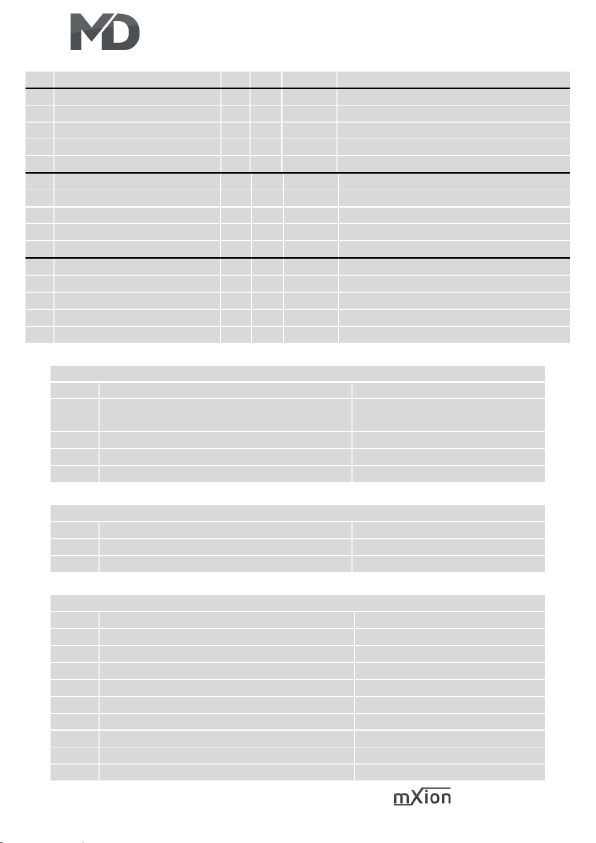
23 DRIVE-S
104
Pendelbetrieb Haltezeit
5 √ 0 – 255
Haltedauer Zeitbasis 5 sek. pro Wert
110
Doppel A Rangierlicht
13 √
siehe Anhang 1
112
Kupplungswalzer Andrückzeit
5 1 – 255
Andrückzeit in Sekunden
113
Kupplungswalzer Wegfahrzeit
5 1 – 255
Abfahrzeit in Sekunden
114
Kupplungswalzer Geschwindig.
30 1 – 255
Geschwindigkeit
116
Taktsimulationskorrektur
5 √ 0 – 255
Taktsimulationskorrektur
120
A1 Schaltbefehlszuordnung
1
siehe Anhang 1
121
A1 Dimmwert
100 √
siehe Anhang 2
122
A1 Bedingung
0 √
siehe Anhang 3
123
A1 Sonderfunktion
0 √
siehe Anhang 4
124
A1 Zeitwert für Sonderfunktion
5 √ 1 – 255
Zeitbasis 0,1 sek. pro Wert
130
A2 Schaltbefehlszuordnung
2
siehe Anhang 1
131
A2 Dimmwert
100 √
siehe Anhang 2
132
A2 Bedingung
0 √
siehe Anhang 3
133
A2 Sonderfunktion
0 √
siehe Anhang 4
134
A2 Zeitwert für Sonderfunktion
5 √ 1 – 255
Zeitbasis 0,1 sek. pro Wert
ANHANG 1 - Schaltbefehlszuordnung
Wert
Verwendung
Bemerkung
0 – 28
0 = Schalten per Lichttaste
1 – 28 = Schalten per F-Taste
30
deaktiv
+64
dauerhaft ausgeschaltet
+128
dauerhaft angeschaltet
ANHANG 2 - Dimmwert
Wert
Verwendung
Bemerkung
0 – 100
Dimmwert
in % (1 % ca. 0,2 V)
+128
auf-/abdimmen
ANHANG 3 - Bedingung
Wert
Verwendung
Bemerkung
0
Dauerbetrieb (normale Funktion)
1
Nur bei Vorwärtsfahrt
2
Nur bei Rückwärtsfahrt
3 Nur im Stand
4
Nur im Stand „vorwärts”
5
Nur im Stand „rückwärts“
6
Nur bei Fahrt
7
Nur bei Fahrt „vorwärts”
8
Nur bei Fahrt „rückwärts“
Page 24
24 DRIVE-S
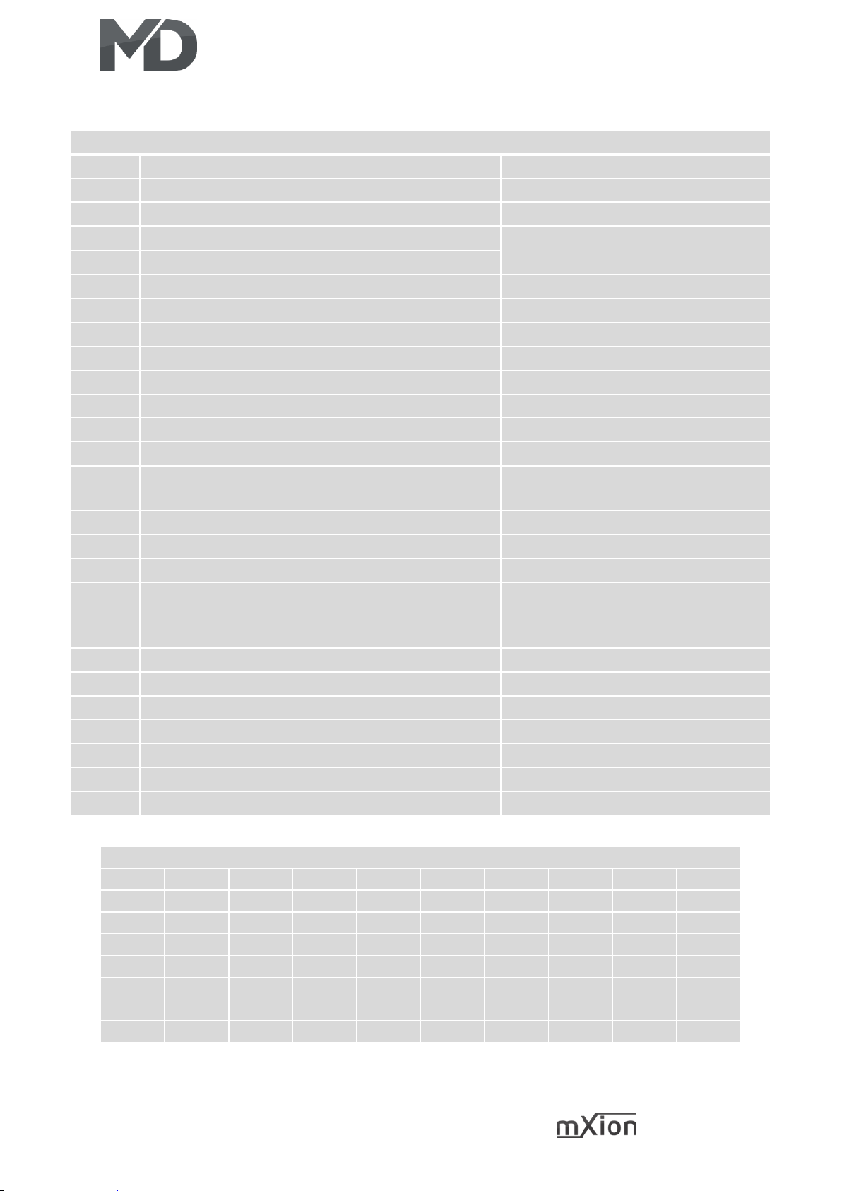
ANHANG 4 - Sonderfunktion
Wert
Verwendung
Bemerkung
0
Keine Sonderfunktion (normaler Ausgang)
1
Blinken symmetrisch
Zeitwert erforderlich (0,1s / Wert)
2
Blinken asymmetrisch kurz AN (1:4)
Zeitwert (0,1s / Wert) bestimmt den
längeren Wert
3
Blinken asymmetrisch lang AN (4:1)
4
Fotoblitz
Zeitwert erforderlich (0,25s / Wert)
5
Kurzzeitfunktion/Monoflop (autom. Abschaltung)
Zeitwert erforderlich (0,1s / Wert)
6
Einschaltverzögerung (verspätete Einschaltung)
Zeitwert erforderlich (0,1s / Wert)
7
Feuersimulation (Kesselfeuer, Lagerfeuer)
8 TV-Simulation
9
Petroleumsimulation
10
Neonröhre Einschaltflackern
11
Defekte Neonröhre
12
Wechselblinker zu gepaartem Ausgang
In Kombination mit dem zweiten
Ausgang (bspw. A1 & A2, A3 & A4)
13
US strobelight
14
US double strobelight
15
US marslight
Zeitwert erforderlich (0,1s / Wert)
16
US ditchlight
In Kombination mit dem zweiten 1.
Ausgang schaltet normales Licht, 2.
Ausgang aktiviert Ditchlight
17
Sodium/Natriumdampflampen
18
Schweißlicht
Am besten blaue LED verwenden
20
Puffercontrol „BC“
21
Taktsimulation
Korrektur über CV 116
24
Kupplungswalzer
+64
Fernlichtfunktion hinzufügen
Fernlichtfunktion über CV 97
+128
Invers
Wert aufaddieren zur Funktion
ANHANG 6 – Grundwerte der frei progr. Fahrkurve (CV67 – 94)
CV
67
68
69
70
71
72
73
74
75
WERT 6 8
10
13
16
19
22
26
31
CV
76
77
78
79
80
81
82
83
84
WERT
36
42
48
54
60
68
76
84
92
CV
85
86
87
88
89
90
91
92
93
WERT
102
112
124
136
152
168
188
208
228
CV
94 - - - - - - - -
WERT
232 - - - - - - - -
Page 25
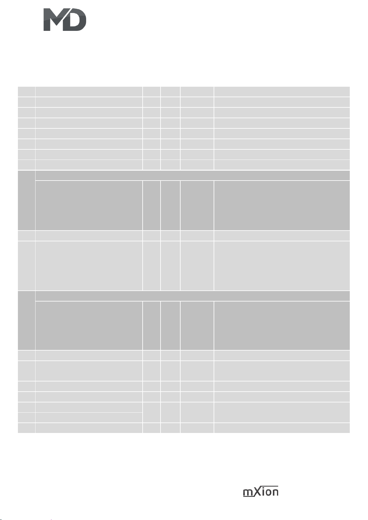
25 DRIVE-S
CV-Table
S = Default, A = Analog operation usable
CV
Description
S A Range
Note
1
Loco address
3 L 1 – 127
if CV 29 Bit 5 = 0 (automatically reset)
2
Starting voltage
5 0 – 255
CV 2 x (1/255 track voltage)
3
Acceleration time
10 √ 0 – 255
CV 3 x 2ms x (1/255 track voltage)
4
Braking time
10 √ 0 – 255
CV 4 x 2ms x (1/255 track voltage)
5
Top speed
200 √ 0 – 255
CV 5 x (1/255 track voltage)
6
Mid speed
50 0 – 255
CV 6 x (1/255 track voltage)
7
Software version
– –
read only (10 = 1.0)
7
Decoder reset functions
6 ranges available
11
16
22
33
44
basic settings (CV 1,11-13,17-19,29-119)
programming lock (CV 15/16)
light outputs (CV50-59)
function outputs (CV 1x0-1x4)
engine functions (CV2-6,9,10,54-25,60-66)
8
Manufacturer ID
160 –
read only
9
Engine frequency
0
√
0 – 4
0 = 16 kHz
1 = 2 kHz
2 = 250 Hz
3 = 60 Hz
4 = 100 kHz
7+8
Register programming mode
Reg8 = CV-Address
Reg7 = CV-Value
CV 7/8 don’t changes his real value
CV 8 write first with cv-number, then CV 7
write with value or read
(e.g.: CV 49 should have 3)
➔ CV 8 = 49, CV 7 = 3 writing
11
Analog timeout
30 30 – 255
1ms each value
13
Function outputs in analog mode
(on if value is set)
3
√
0 – 255
add the values to the desired function!
A1 = 1, A2 = 2
15
Programming lock (key)
205 0 – 255
to lock only change this value
16
Programming lock (lock)
205 0 – 255
changes in CV 16 will change CV 15
17
Long loco address (high)
128 L 128 –
10239
activ only if CV 29 Bit 5 = 1
(automatically set if change CV 17/18)
18
Long loco address (low)
19
Multi traction address
0 L 1 – 127
loco address for multi traction
Page 26
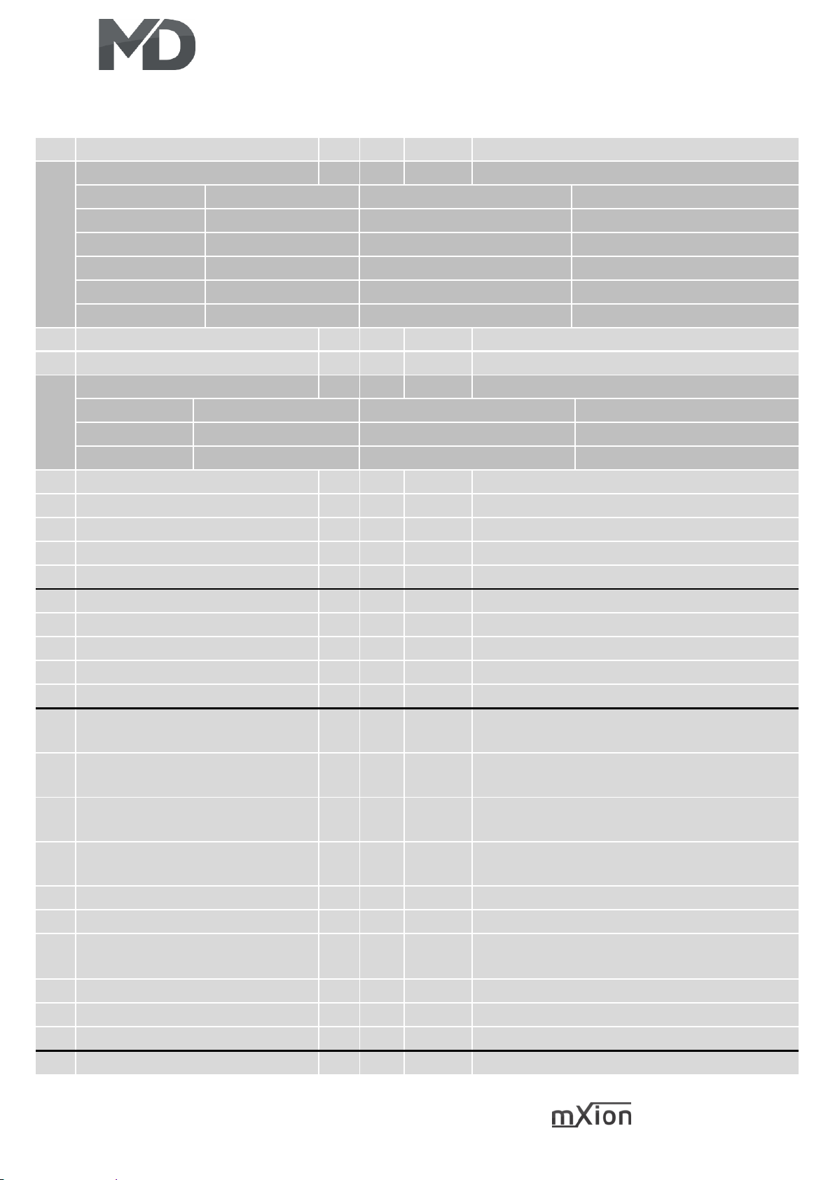
26 DRIVE-S
S = Default, A = Analog operation usable
CV
Description
S A Range
Note
29
NMRA configuration
6 √
bitwise programming
Bit
Value
OFF (Value 0)
ON
0
1
standard driving direction
reverse driving direction
1
2
14 speed steps
28/128 speed steps
2
4
only digital operation
digital + analog operation
4
16
internal driving courve
programm. drive courve
5
32
short loco address (CV 1)
long loco address (CV 17/18)
30
Command for pendula control
28 √
see attachment 1
47
Buffer runtime
5 √ 1 – 255
1 sec / Value
49
MD configuration
23 √
bitwise programming
Bit
Value
OFF (Value 0)
ON
5
32
light outputs normal
light outputs invers
7
128
digital -> analog normal
digital direction holding
50
LF command allocation
0
see attachment 1
51
LF dimming value
15 √
see attachment 2, configured to 5V
52
LF condition
1 √
see attachment 3
53
LF special function
64 √
see attachment 4
54
LF time for special function
10 √ 1 – 255
time base (0,1s / value)
55
LB command allocation
0
see attachment 1
56
LB dimming value
15 √
see attachment 2, configured to 5V
57
LB condition
2 √
see attachment 3
58
LB special function
64 √
see attachment 4
59
LB time for special function
10 √ 1 – 255
time base (0,1s / value)
63
Time for CV96 hand brake
0 0 – 255
0 = always normal op
1 – 255 wait time in seconds
66
Forward-Trimm
255
√
1 – 255
reduce the maximum speed forward
(CV66 * CV5 / 255)
67-
94
Freely programmable speed
curve
√ 1 – 255
see attachment 6
95
Forward-Trimm
255
√
1 – 255
reduce the maximum speed backward
(CV95 * CV5 / 255)
96
hand brake f-switch
13
see attachment 1 and CV63
97
Far away light
14
see attachment 1, attachment 4
98
Random generator
0 √ 0 – 255
add the values to the desired function!
A1 = 1, A2 = 2
99
Wait time by direction change
0 √ 0 – 255
time base (0,5s / value)
100
Shunting mode
15
see attachment 1
101
Switchable delay times
16
see attachment 1
102
Shuttle mode speed
100
√
1 – 255
Speed
Page 27
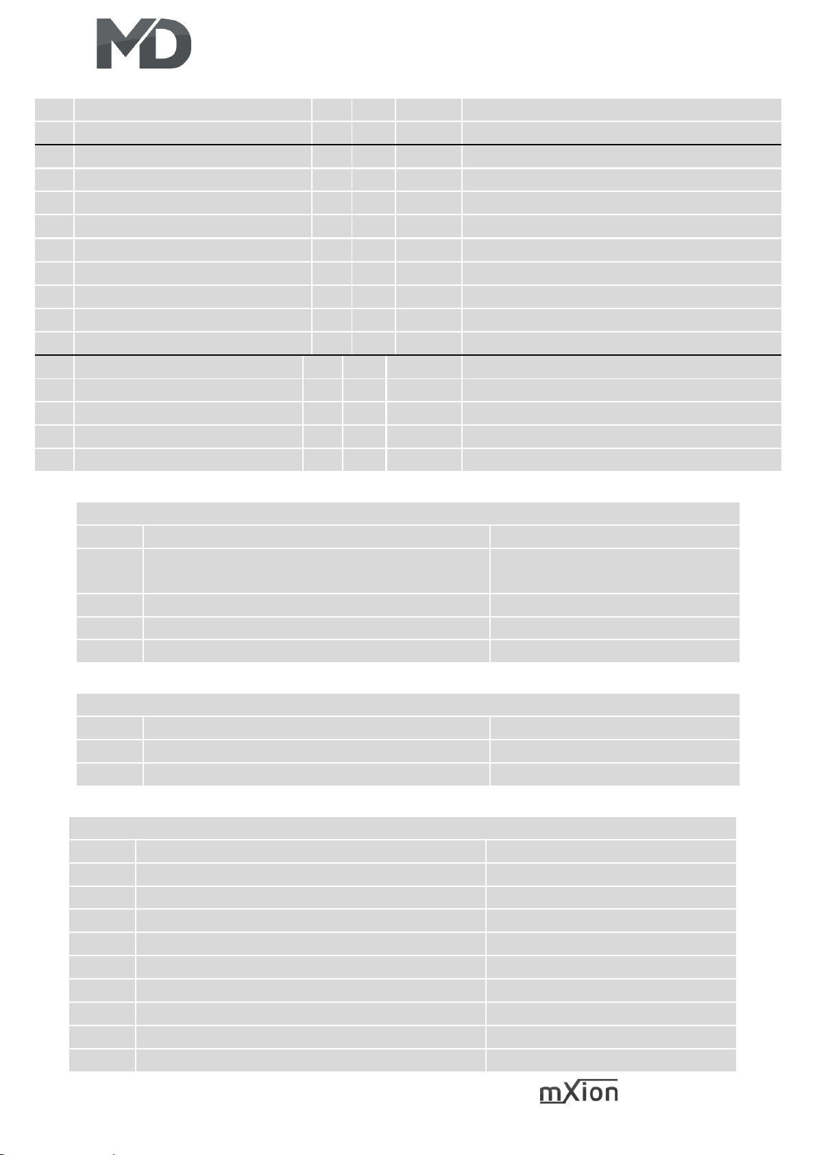
27 DRIVE-S
103
Shuttle mode drive time
5 √ 0 – 255
1 – 255 shuttle train drive time (5sek. /value)
104
Shuttle mode wait time
5 √ 0 – 255
Wait time (5sek. /value)
110
Double-A shunting light
4 √
see attachment 1
112
Kupplungswalzer press time
5 1 – 255
press time in seconds
113
Kupplungswalzer drive time
5 1 – 255
drive away (free drive) time in seconds
114
Kupplungswalzer speed
30 1 – 255
speed of the loco
120
A1 command allocation
1
see attachment 1
121
A1 dimming value
100 √
see attachment 2
122
A1 condition
0 √
see attachment 3
123
A1 special function
0 √
see attachment 4
124
A1 time for special function
5 √ 1 – 255
time base (0,1s / value)
130
A2 command allocation
2
see attachment 1
131
A2 dimming value
100 √
see attachment 2
132
A2 condition
0 √
see attachment 3
133
A2 special function
0 √
see attachment 4
134
A2 time for special function
5 √ 1 – 255
time base (0,1s / value)
ATTACHMENT 1 – Command allocation
Value
Application
Note
0 – 28
0 = Switch with light key
1 – 28 = Switch with F-key
30
deactive
+64
permanent off
+128
permanent on
ATTACHMENT 2 – Dimming value
Value
Application
Note
0 – 100
dimming value
in % (1 % is around 0,2 V)
+128
fade in/out
ATTACHMENT 3 – Condition
Value
Application
Note
0
permanent (normal function)
1
forward only
2
backward only
3 standing only
4
standing „forward“ only
5
standing „backward“ only
6
driving only
7
driving „forward“ only
8
driving „backward“ only
Page 28
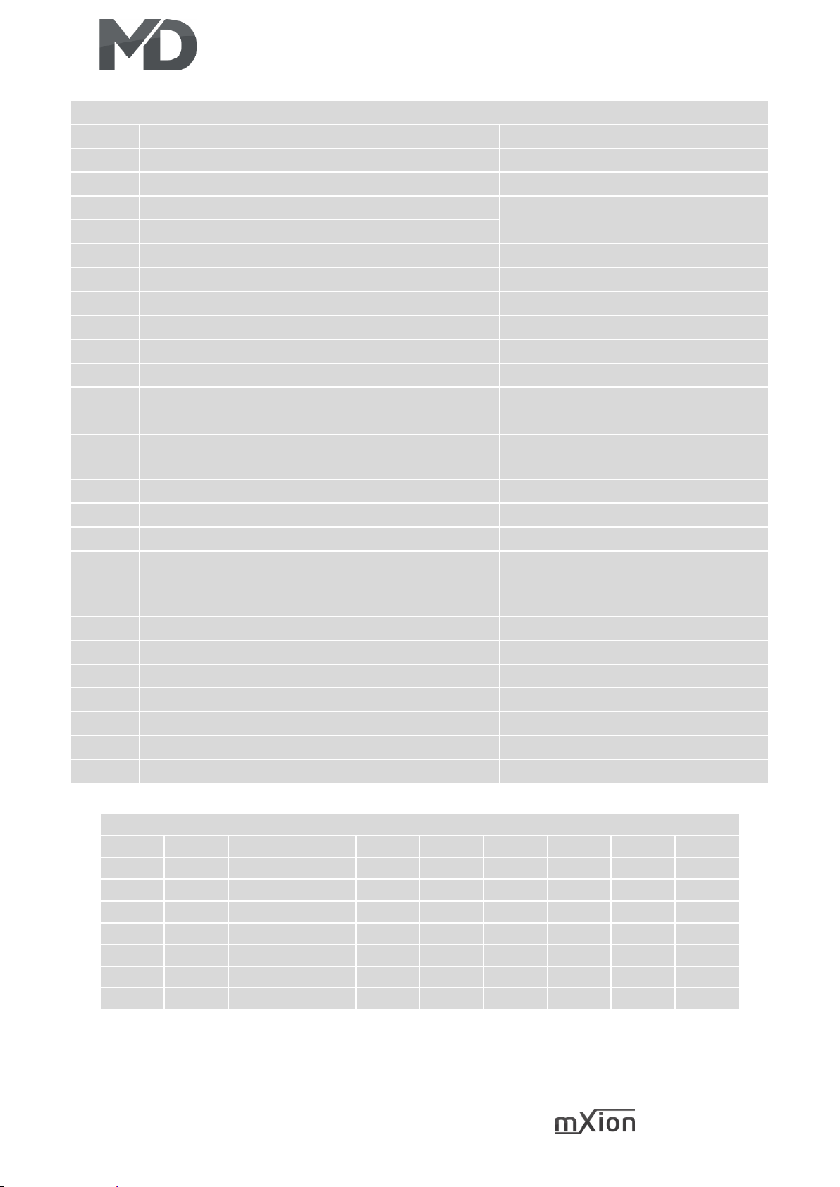
28 DRIVE-S
ATTACHMENT 4 – Special function
Value
Application
Note
0
no special function (normal output)
1 flash symetric
time base (0,1s / value)
2
flash asymetric short ON (1:4)
time base (0,1s / Value) is for the
long value
3
flash a symetric long ON (4:1)
4
Photographer flash
time base (0,25s / value)
5
monoflop (automatic switch off)
time base (0,1s / value)
6
switch on delayed
time base (0,1s / value)
7
firebox
8 TV flickering
9 petroleum flickering
10
flourescent tube
11
defective flourescent tube
12
alternating flash to paired output
in combination with second output
(e.g. A1 & A2, A3 & A4)
13
US strobelight
14
US double strobelight
15
US marslight
time base (0,1s / value)
16
US ditch light
in combination with second output
(e.g. A1 & A2, A3 & A4), 1st output
normal light, 2nd ditch light function
17
sodium lamp
18
welding light
use with blue led
20
Buffer control “BC”
21
Clock simulation
CV116 corrects time
24
Kupplungswalzer
+64
Far away light adding
Far away light over CV 97
+128
invers
add value to function
ATTACHMENT 6 – Basic values of freely progr. driving curve (CV67 – 94)
CV
67
68
69
70
71
72
73
74
75
WERT 6 8
10
13
16
19
22
26
31
CV
76
77
78
79
80
81
82
83
84
WERT
36
42
48
54
60
68
76
84
92
CV
85
86
87
88
89
90
91
92
93
WERT
102
112
124
136
152
168
188
208
228
CV
94 - - - - - - - -
WERT
232 - - - - - - - -
Page 29

29 DRIVE-S
Technische Daten Technical data
Spannung: Power supply:
0-27V DC/DCC 0-27V DC/DCC
0-22V AC 0-22V AC
Stromaufnahme: Current:
15mA (ohne Funktionsausgänge) 15mA (with out functions)
Maximaler Funktionsstrom: Maximum function current:
A1-A2 je 1A A1-A2 each 1 Amps.
LV/LH je 0.5 A LF/LB each 0.5 Amps.
Maximaler Motorstrom Motor output
1.5A (kurzzeitig 2A) 1.5 Amps (peak 2 Amps)
Maximaler Gesamtstrom: Maximum current:
3A 3 Amps.
Temperaturbereich: Temperature range:
-20 bis 60°C -20 up to 60°C
Abmaße L*B*H (cm): Dimensions L*B*H (cm):
1.1*3*0.3 1.1*3*0.3
HINWEIS: Um Kondenswasserbildung NOTE: In case you intend to utilize this
zu vermeiden benutzen Sie die Elektronik device below freezing temperatures, make
bei Temperaturen unter 0°C nur, wenn sure it was stored in a heated environment
diese vorher aus einem beheizten Raum before operation to prevent the generation
kommt. Im Betrieb sollte sich kein weiteres of condensed water. During operation is
Kondenswasser bilden können. sufficient to prevent condensed water.
Page 30

30 DRIVE-S
Garantie, Reparatur Warranty, Service, Support
MD Electronics gewährt die MD Electronics warrants this product
Fehlerfreiheit dieses Produkts für ein against defects in materials and
Jahr. Die gesetzlichen Regelungen workmanship for one year from the
können in einzelnen Ländern abweichen. original date of purchase. Other countries
Verschleißteile sind von der Garantieleistung might have different legal warranty
ausgeschlossen. Berechtigte Beanstandungen situations. Normal wear and tear,
werden kostenlos behoben. Für Reparatur- consumer modifications as well as improper
oder Serviceleistungen senden Sie das use or installation are not covered.
Produkt bitte direkt an den Hersteller. Peripheral component damage is not covered
Unfrei zurückgesendete Sendungen werden by this warranty. Valid warrants claims will be
nicht angenommen. Für Schäden durch serviced without charge within the warranty
unsachgemäße Behandlung oder Fremdeingriff period. For warranty service please return
oder Veränderung des Produkts besteht the product to the manufacturer. Return
kein Garantieanspruch. Der Anspruch auf shipping charges are not covered by
Serviceleistungen erlischt unwiderruflich. MD Electronics. Please include your proof of
Auf unserer Internetseite finden Sie die purchase with the returned good. Please
jeweils aktuellen Broschüren, check our website for up to date brochures,
Produktinformationen, Dokumentationen product information, documentation and
und Softwareprodukte rund um software updates. Software updates you can
MD-Produkte. do with our updater or you can send us
Softwareupdates können Sie mit the product, we update for you free.
unserem Updater durchführen,
oder Sie senden uns das Produkt zu;
wir updaten für Sie kostenlos.
Irrtümer und Änderungen vorbehalten. Errors and changes excepted.
Page 31
31 DRIVE-S
Hotline Hotline
Bei Serviceanfragen und Schaltplänen For technical support and schematics for
für Anwendungsbeispiele richten Sie sich application examples contact:
bitte an:
MD Electronics MD Electronics
www.md-electronics.de www.md-electronics.de
MD-TV MD-TV
 Loading...