

8901155100
EN
USE AND INSTALLATION MANUAL

INSTALLATION AND USE MANUAL
Contents
page 2
Contents
Technical service – MCZ S.p.A. all rights reserved - Reproduction prohibited
INTRODUCTION .................................................................................................................................... 4
1. WARNINGS AND WARRANTY CONDITIONS ...................................................................................... 5
1.1. SAFETY WARNINGS ................................................................................................................................ 5
1.2. OPERATING WARNINGS .......................................................................................................................... 5
1.3. WARRANTY CONDITIONS ........................................................................................................................ 6
1.3.1. Restrictions ................................................................................................................................ 6
1.3.2. Exclusions .................................................................................................................................. 6
1.4. IMPORTANT INFORMATION FOR CORRECT DISPOSAL OF THE PRODUCT IN ACCORDANCE WITH EC
DIRECTIVE 2002/96/EC .................................................................................................................................. 6
2. INSTALLATION IN ACCORDANCE WITH UNI 10683 .......................................................................... 7
2.1. OPERATING AREA ................................................................................................................................... 7
2.2. PRECAUTIONS ........................................................................................................................................ 7
2.3. CONNECTION TO THE EXTERNAL AIR INTAKE .......................................................................................... 8
2.4. CONNECTION TO THE FLUE PIPE ............................................................................................................ 9
2.5. FLUE PIPE .............................................................................................................................................. 9
2.5.1. Examples of flue pipes .............................................................................................................. 10
2.6. COWL .................................................................................................................................................. 11
3. DIMENSIONS AND TECHNICAL SPECIFICATIONS ........................................................................... 12
3.1. Dimensions of the Forma Wood 65 ......................................................................................................... 12
3.2. Dimensions of the Forma Wood 75 ......................................................................................................... 13
3.3. Dimensions of the Forma Wood 95 ......................................................................................................... 14
3.4. Dimensions of the Forma Wood B95 ....................................................................................................... 15
3.5. Dimensions of the Forma Wood 115 ....................................................................................................... 16
3.6. Technical specifications ......................................................................................................................... 17
4. INSTALLATION AND ASSEMBLY ...................................................................................................... 20
4.1. PREPARATION AND UNPACKING ............................................................................................................ 20
4.2. SELECTION OF OPERATING MODE ......................................................................................................... 20
4.2.1. Natural convection (VN)............................................................................................................ 21
4.2.2. Forced convection (VF) ............................................................................................................. 21
4.3. RELEASE OF COUNTERWEIGHTS ........................................................................................................... 21
4.4. POSITIONING ....................................................................................................................................... 21
4.5. ADJUSTMENT OF HEIGHT AND BALANCING............................................................................................ 22
4.6. EXTERNAL AND INTERNAL AIR INTAKE .................................................................................................. 23
4.6.1. Combustion air inlet ................................................................................................................. 23
4.6.2. Air inlet for natural ventilation ................................................................................................... 23
4.6.3. Air inlet for forced ventilation .................................................................................................... 23
4.6.3.1. Ducts for kit COMFORT AIR ................................................................................................ 23
4.7. CONNECTION TO THE FLUE PIPE .......................................................................................................... 24
4.8. INSTALLATION OF CLADDING AND HOOD LINER .................................................................................... 24
4.9. INSULATING A WOODEN BEAM ............................................................................................................. 25
4.10. INSULATION OF FIREPLACE STOVE ................................................................................................. 25
4.10.1. Hood ventilation nozzles. ....................................................................................................... 25
5. COMFORT AIR KIT– NATURAL VENTILATION AND FORCED VENTILATION .................................... 26
5.1.1. Components of natural ventilation kit with and without illumination ............................................ 26
5.1.2. Components of forced ventilation kit with and without illumination ............................................. 26
5.2. ACCESSORIES....................................................................................................................................... 27
5.2.1. Air outlets of natural ventilation kit with and without illumination ............................................... 27
5.2.2. Air outlets for forced ventilation kit ............................................................................................ 28
5.3. INSTALLATION OF THE COMFORT AIR KIT............................................................................................. 29
5.3.1. Variation for air outlet with container ........................................................................................ 30
5.3.2. Variation for air outlet with illumination ..................................................................................... 30
5.3.2.1. Maintenance of air outlet with illumination .......................................................................... 31

INSTALLATION AND USE MANUAL
Contents
page 3
Contents
Technical service – MCZ S.p.A. all rights reserved - Reproduction prohibited
5.4. CONTROL UNIT .................................................................................................................................... 32
5.4.1. Composition of control unit ....................................................................................................... 32
5.4.2. Positioning of the control unit ................................................................................................... 32
5.5. GENERAL INFORMATION ON THE CONTROL UNIT .................................................................................. 33
5.5.1. On/off ..................................................................................................................................... 33
5.5.2. Operation ................................................................................................................................ 33
5.5.3. Safety function ......................................................................................................................... 34
5.5.4. Light on (if present) ................................................................................................................. 34
5.5.5. Replacing the fuse of the control unit ........................................................................................ 34
5.6. INSTALLATION OF TEMPERATURE PROBE ............................................................................................. 35
5.7. DOOR OPEN SWITCH ............................................................................................................................ 35
5.8. CONNECTIONS ..................................................................................................................................... 36
5.9. REPLACING THE FAN ............................................................................................................................ 37
6. OPERATION ..................................................................................................................................... 38
6.1. PRE-LIGHTING WARNINGS .................................................................................................................... 38
6.2. OPERATING TEST ................................................................................................................................. 38
6.2.1. Phases for first test lighting ...................................................................................................... 39
6.3. CHOICE OF FUEL .................................................................................................................................. 39
6.4. FIRST LIGHTING ................................................................................................................................... 40
6.5. LOADING THE FUEL .............................................................................................................................. 41
6.6. CONTROL OF COMBUSTION .................................................................................................................. 42
6.7. EMERGENCY SITUATIONS ..................................................................................................................... 42
7. MAINTENANCE AND CLEANING ....................................................................................................... 43
7.1. CLEANING TO BE PERFORMED BY THE USER ......................................................................................... 43
7.1.1. Cleaning the glass .................................................................................................................... 43
7.1.2. Cleaning out the ashes ............................................................................................................. 43
7.1.3. Cleaning the refractory material walls (ALUTEC®) ....................................................................... 43
7.1.4. Lubrication and routine maintenance of the extensible guides ..................................................... 44
7.1.5. Maintenance of kit VF (if installed) ............................................................................................ 44
7.1.5.1. Electric fan ........................................................................................................................ 44
7.1.5.2. Control unit COMFORT AIR ................................................................................................ 45
7.1.5.3. Wiring............................................................................................................................... 45
7.2. CLEANING TO BE DEALT WITH BY SPECIALIZED TECHNICIAN ................................................................ 45
7.2.1. Cleaning flue pipe .................................................................................................................... 45
INSTALLATION AND USE MANUAL
Chapter 1
page 4
Introduction
Technical service – MCZ S.p.A. all rights reserved - Reproduction prohibited
WARNING:
This warning symbol found in various
points in this manual indicates that the
user should carefully read and understand
the message to which it refers since
neglect to follow these instructions
could cause serious fireplace stove
damage or injury to the user.
INFORMATION:
This symbol intends to emphasise
important information for good fireplace
stove operations. Failure to observe these
instructions could jeopardise product use
and operations may be unsatisfactory
INTRODUCTION
Dear customer,
Thank you for choosing an MCZ product, specifically a
fireplace stove of the Forma line.
We are sure that, with use, you will appreciate the
quality of an attentively designed and tested product.
Our goal is to combine technology with easy use and,
above all, safety.
For best fireplace stove operations and to fully
enjoy the heat and sense of well being it will
spread throughout your home, we suggest you
carefully read this booklet before use. Please
contact your dealer for full assistance in
resolving any doubts or problems.
Congratulations on your choice and remember, the
fireplace stove MUST NEVER be used by children
who should always be kept at a safe distance!
Revisions to the publication
In order to improve the product, the Manufacturer
reserves the right to modify and update this
publication without prior notice.
Reproduction, even partial, of this manual without the
Manufacturer's authorisation is prohibited.
Manual preservation
Please take care of this manual and keep it in a
place that can be quickly and easily reached.
If this manual should be lost or destroyed, or if it
is in poor condition, ask for a copy from your
retailer or directly from the manufacturer,
providing product identification data.
How to read the manual
An essential item or one that requires specific
attention is published in “bold”.
“Italics"
NOTE: the “NOTE” provides the reader with
additional information on the subject.
are used for any additional clarification.
These symbols signal specific messages
in this booklet

INSTALLATION AND USE MANUAL
Chapter 1
page 5
Warnings and warranty conditions
Technical service – MCZ S.p.A. all rights reserved - Reproduction prohibited
Installation, electrical connection,
functional check and maintenance of this
appliance must only be performed by
qualified or authorised personnel.
Install the closed fireplace in compliance
with the applicable regulations in force in
the place, region or country.
This appliance must not be used by anyone
(including children) with limited physical,
sensory or mental skills or with little
experience and knowledge, unless they are
supervised or have been instructed to use
the device by the person in charge of its
safety.
Only use the fuel recommended by MCZ.
The appliance must not be used as an
incinerator. The use of liquid fuel is strictly
forbidden.
For correct use of the fireplace stove and
accessories, and to prevent accidents, always
follow the instructions in this booklet.
Before beginning any operation, anyone who
uses the stove must read and understand the
entire contents of this instruction booklet.
The fireplace stove must be used only for its
intended purpose. Any other use is considered
improper and therefore hazardous.
Check the conditions of the surface that will
support the weight of the stove. If it is made of
flammable material such as wood, carpet, or
plastic, provide suitable insulation.
Avoid installation in rooms with B type gas
devices, hoods with or without exhaust, heat
pumps, collective ventilation conduits.
Do not install several flue pipes in one room, and
avoid having a stairwell in the vicinity. Check that
in adjacent connected room there are not any
units whose simultaneous use would create
negative pressure in one of the two rooms.
The user is fully liable for improper product use,
releasing MCZ from any civil or penal liabilities.
Any tampering with the fireplace stove, or use of
non-original spare parts, may be hazardous to
the user and releases MCZ from any civil or penal
liability.
Parts of the surfaces of the fireplace stove are
very hot (door, handle, glass). Therefore, avoid
direct contact with these parts unless wearing
protective clothing or specific means such as, for
example, heat protective gloves or "cold"
activation devices.
Carefully explain this hazard to elderly people,
disabled people and particularly to all children,
keeping them away from the fireplace stove while
it is in operation.
Incorrect installation or poor maintenance (not
compliant with the provisions of this manual)
may cause damages to persons, animals or
property. MCZ is not civilly or criminally liable in
these cases.
Turn off the fireplaces stove in the event of faults
or poor operations.
Never place flammable materials closer than 150
cm to the fireplace stove.
If the chimney flue draught is poor (due to bad
weather or improper installation), start the fire
decisively while keeping the door slightly ajar.
When you close the door, keep the air register
completely open. Use small pieces of dry wood. If
combustion problems continue, please contact a
specialized technician.
Install the fireplace stove in a location which is
suitable for fire fighting, and equipped with all
services such as air, water and electricity supply
and smoke discharge.
Do not light the fire with flammable materials.
To clean the appliance's chimney, remove the
smoke deflector. To remove it correctly, lift the
front and at the same time slide it forward in
order to free it from rear support.
INFORMATION:
For any problem, please contact your dealer or
MCZ qualified and authorised personnel and
always request original spare parts for repairs.
Check and periodically clean the smoke exhaust
stack as foreseen by current regulations in the
country of installation.
If there is a fire in the flue pipe, keep the door of
the fireplace stove and the combustion air
register closed at all times. Request assistance
from the competent authorities.
Carefully conserve the instruction booklet. It
must remain with the fireplace stove for its entire
life cycle. If the stove is sold or transferred to
another user, make sure the manual
accompanies the product.
If lost, please request a copy from your dealer or
from MCZ.
1. WARNINGS AND WARRANTY
CONDITIONS
1.1. SAFETY WARNINGS
1.2. OPERATING WARNINGS
INSTALLATION AND USE MANUAL
Chapter 1
page 6
Warnings and warranty conditions
Technical service – MCZ S.p.A. all rights reserved - Reproduction prohibited
Specifically, glass is guaranteed from
the moment the MCZ installation
technician certifies its integrity when
installation is completed.
SERVICE REQUESTS
Service requests must be addressed
to the dealer who shall forward the
request to MCZ technical assistance.
MCZ is not liable in the event the
product and any other accessory is
improperly used or modified without
authorisation.
Only original MCZ spare parts must be
used for all replacements.
1.3. WARRANTY CONDITIONS
MCZ guarantees the product, except for the
elements subject to normal wear listed below, for
two years from the date of purchase proven by a
document that indicates the dealer's name and date
of sale, if the completed warranty certificate was
returned within 8 days and if the product was installed
and inspected by a specialised installation technician
and according to the detailed instructions indicated in
the instruction manual supplied with the product.
The warranty includes the free replacement or repair
of parts recognised as factory defective.
1.3.1. Restrictions
The above guarantee does not cover components
relating to electrical parts, on which the guarantee
period is 1 year from the purchase of the product,
documented as specified above. The warranty does
not cover parts subject to normal wear such as:
gaskets, glass, and all removable fire box parts.
Replaced parts will be guaranteed for the remaining
warranty period from the date of product purchase.
1.3.2. Exclusions
The warranty does not cover any part that may
be defective due to negligence or careless use,
incorrect maintenance, installation non
compliant with that specified by MCZ (see
relevant chapters in this manual).
MCZ refuses to accept any responsibility for any
damage which may be caused, directly or indirectly,
by persons, animals or things as a result of the failure
to observe all the provisions set forth in the instruction
booklet, especially those concerning warnings on the
subject of installation, use and maintenance of the
appliance.
In the event of product inefficiency, please contact
your dealer and/or area importer.
Damages caused by transport and handling are not
covered by the warranty.
Exclusively refer to the supplied manual for product
installation and use.
The warranty is null and void in the event of damage
due to tampering, weather, natural calamities,
lightening, fire, defective electrical and hydraulic
systems and the lack or incorrect maintenance as per
the manufacturer's instructions.
1.4. IMPORTANT INFORMATION FOR
CORRECT DISPOSAL OF THE PRODUCT
IN ACCORDANCE WITH EC DIRECTIVE
2002/96/EC
.
At the end of its working life, the product must not be
disposed of as urban waste.
It must be taken to a special local authority
differentiated waste collection centre or to a dealer
providing this service.
Disposing of a appliance separately avoids possible
negative consequences for the environment and
health deriving from inappropriate disposal and
enables the constituent materials to be recovered to
obtain significant savings in energy and resources.
As a reminder of the need to dispose of appliances
separately, the product is marked with a crossed-out
wheeled dustbin.
INSTALLATION AND USE MANUAL
Chapter 2
page 7
Theoretical notions for installation
Technical service – MCZ S.p.A. all rights reserved - Reproduction prohibited
Fireplace stoves may not be installed in
bedrooms, bathrooms and where another
heating device is installed without autonomous
air flow (fireplace, stove, etc.).
Placing the fireplace stove in explosive
environments is prohibited.
The floor of the room where the fireplace stove
is to be installed must be strong enough to
support its weight.
In the event of wood floors, install a protective
covering in accordance with current regulations
in the country of installation.
If walls are not flammable, install the fireplace
stove at least 5 cm from the walls.
2. INSTALLATION IN ACCORDANCE WITH UNI
10683
2.1. OPERATING AREA
For good operations and good heat distribution, the fireplace stove
should be positioned in a place where the air required for combustion
can flow (at least 60 m3/h must be available) according to installation
standards and current regulations in the country of installation.
The room volume must not be less than 60 m3.
Air must enter through permanent apertures on the walls (near the
fireplace stove) that open outdoors with a minimum section of 360 cm2.
These apertures (air vents) must be made so as not to be obstructed in
any way.
Air can also be taken from adjacent rooms as long as these are
equipped with outdoor air vents and not bedrooms or bathrooms or
rooms where fire hazards do not exist such as garages, wood sheds,
flammable material warehouses, strictly observing the provisions of
current regulations.
2.2. PRECAUTIONS
The fireplace stove must be installed in a suitable surface that permits
routine opening and maintenance operations.
The room must be:
suitable for room operating conditions
equipped with power supply 230V 50 Hz
equipped with an adequate smoke exhaust system
equipped with outdoor ventilation
provided with an earth connection complying with CEI
INSTALLATION AND USE MANUAL
Chapter 2
page 8
Theoretical notions for installation
Technical service – MCZ S.p.A. all rights reserved - Reproduction prohibited
IMPORTANT!
The fireplace stove must be installed and
assembled by qualified personnel.
The fireplace stove must be connected to a flue
pipe or other vertical smoke stack that can
discharge smoke at the highest point of the
house.
The fireplace stove must be connected to a flue
pipe or an internal or external vertical duct
conforming to current standards UNI 7129 - 7131
9615.
Smoke is generated from burning wood and,
therefore, may dirty adjacent or nearby walls.
Before positioning the fireplace stove, you must
make a hole for the intake of external air.
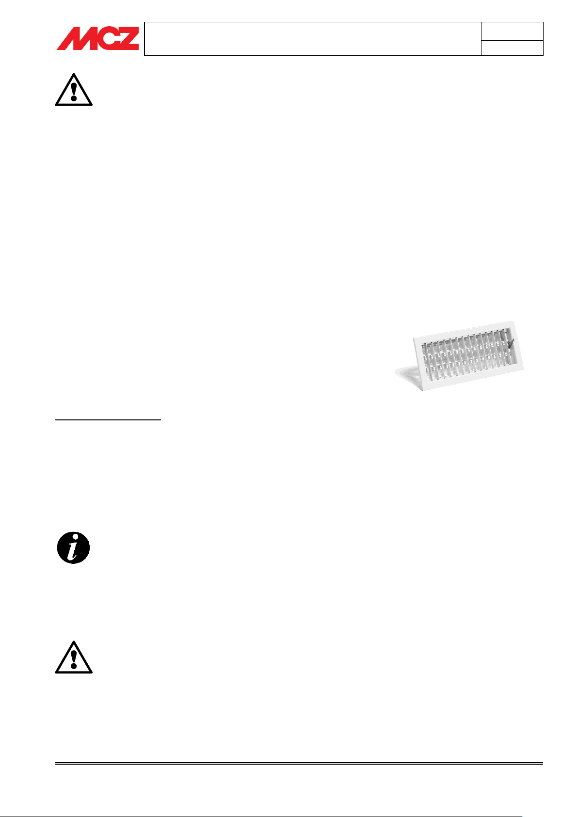
Remember that the ventilation grills always have a cm2
useful section on one side. When selecting the grill and hole
dimension, make sure the useful grill section is greater than
or equal to the section required by MCZ for product
operations.
Connecting the air outlet directly to the fireplace stove is not
mandatory but the above mentioned section must guarantee
about 50 m³/h of air. See standard UNI 10683 REV.
IMPORTANT!
Air flow may also be obtained from a room adjacent
to the installation room as long as this flow is free
through permanent apertures that directly
communicate with the outdoors; avoid air outlets
connecting with heating units, garages, kitchens or
bathrooms.
2.3. CONNECTION TO THE EXTERNAL AIR INTAKE
The room where the stove is installed must have at least as much air as
requested by normal combustion of the equipment and by room
ventilation. This may take place through permanent apertures in the
room walls that lead directly outdoors or ventilated rooms according to
UNI 10683 REV.
For this purpose, drill a hole with minimum 360 cm² free section near
the fireplace stove (22 cm diameter or a 20x18cm rectangle), protected
by an indoor and outdoor grille.
The air intake must also:
directly communicate with the installation room
be protected by a grill, made of metallic anti-insect mesh or a
suitable protection as long as it does not reduce the minimum
section.
be installed so as to avoid obstruction
for ducts, up to 3.5 linear metres, increase the section by about
5% while increased by 15% for larger measurements.
INSTALLATION AND USE MANUAL
Chapter 2
page 9
Theoretical notions for installation
Technical service – MCZ S.p.A. all rights reserved - Reproduction prohibited
If metal connecting pipes are used, they must be
insulated with suitable material such as ceramic fibre
matting, to avoid deterioration of the masonry and of
the decorative hood liner.
IMPORTANT!
Any increase in the section of the connecting pipe
must start immediately above the hood of the
fireplace and not along the flue pipe section.
The flue pipe is of primary importance for the correct
functioning and safety of your fireplace stove.
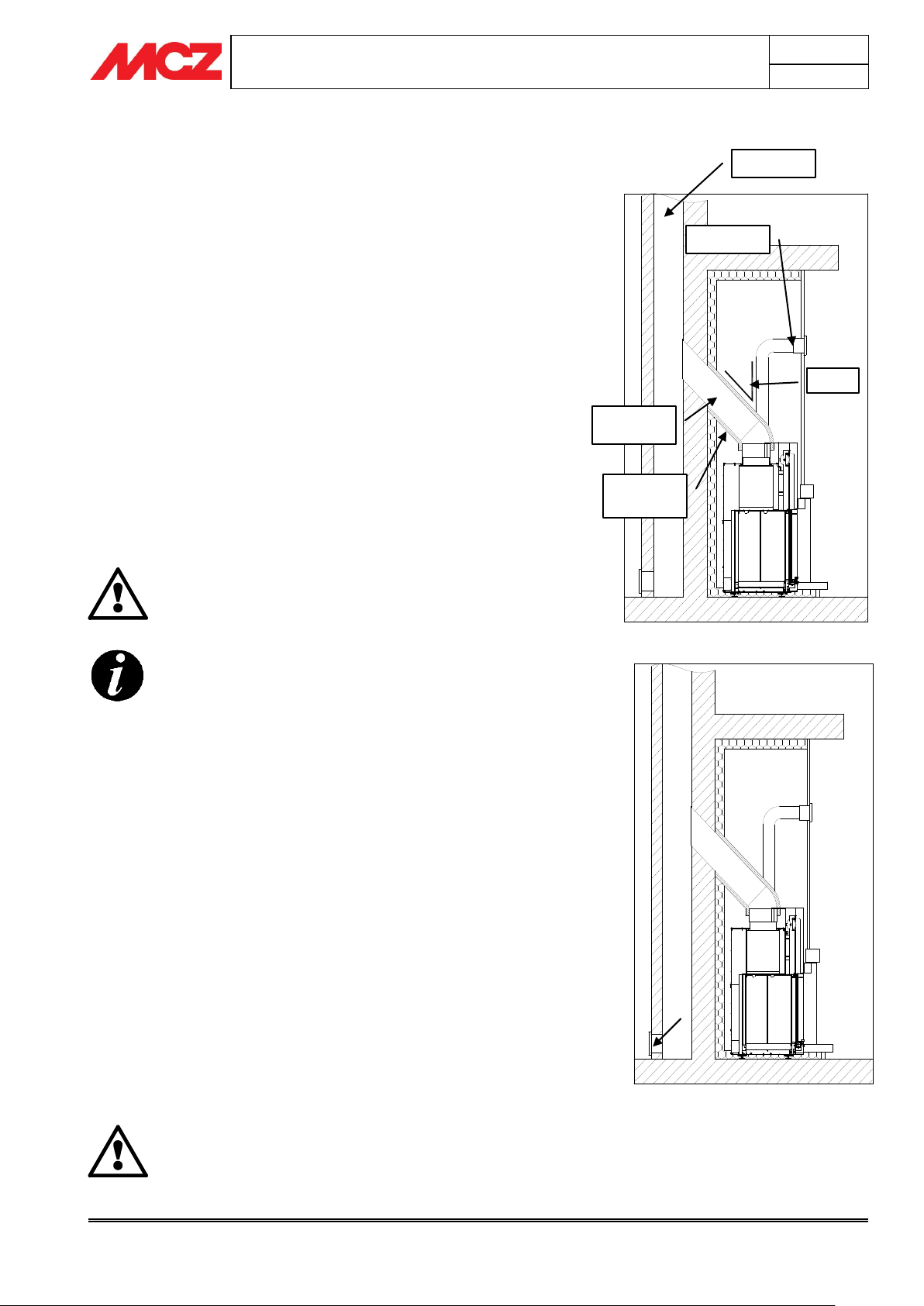
Example of fireplace stove connection
Flue pipe
Hood grille
Smoke
connection
Ceramic fibre
insulation
45° max
Typical diagram of a correctly laid flue pipe
with a chamber including a sealed hatch to
collect and remove solid materials produced
during combustion positioned at the foot of
the external rising section.
2.4. CONNECTION TO THE FLUE PIPE
The connection to the flue pipe is a very important element. The
connection must be made with a great deal of care; in the event of
erroneous or anomalous construction, it is extremely difficult to remedy
without damaging the hood liner. In addition, the connection is made in
a part of the stove where temperatures are very high, and for this
reason it is important to use materials that are capable of resisting heat
and also the acidity of the fumes produced by combustion.
Before beginning work, please note the following:
The connection must have a maximum inclination of 45° to
prevent excessive build up of condensation produced in the
initial start-up stages of the closed fireplace and/ or excessive
adhesion of creosote. This also prevents smoke evacuation from
slowing down.
The unions must be made of metal and suitable for the
specific operating conditions of the product and marked
EC (EN1856-2). The use of flexible and extending metal
pipes is not permitted.
The elements of the connection must be perfectly sealed.
The connection to the flue pipe must be neither too long (to
prevent obstructions) nor too short (to prevent smoke leakage).
2.5. FLUE PIPE
The flue pipe is a fundamental element in discharging smoke and
therefore must have the following requisites:
be waterproof and thermally insulated.
be made of suitable heat-proof materials that are resistant to
the effects of combustion products and any possible
condensation.
have a vertical arrangement with deviations from the axis of
no more than 45° and without kinks.
must be suitable for the specific operating conditions of the
product and marked EC (EN1856-1, EN1443).
must be suitably sized to accommodate the draught/smoke
disposal requirements necessary for the correct functioning of
the product (EN13384-1).
have an internal section which is preferably circular.
be cleaned if pre-existing and has operated beforehand.
INSTALLATION AND USE MANUAL
Chapter 2
page 10
Theoretical notions for installation
Technical service – MCZ S.p.A. all rights reserved - Reproduction prohibited
IMPORTANT !
In the event of doubt on your chimney flue operations or
that its dimensions are different from those recommended,
we highly suggest an authorised MCZ technician inspect and
measure chimney flue performance (micro-gauge
measurements)
MCZ s.p.a. shall not be held liable for poor operation of the
fireplace stove that is due to a flue pipe of improper size or
installation that does not comply with provided
requirements.
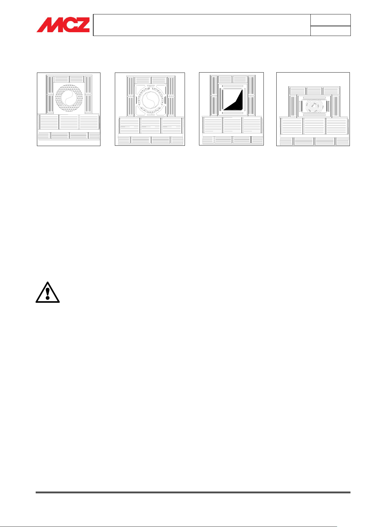
AISI 316 stainless steel
flue pipe with dual
chamber insulated with
ceramic wool or equivalent
resistant to 400°C.
EXCELLENT
Flue pipe in refractory brick
with insulated double wall and
external coat of cement mix
lightened with honeycomb
material such as clay.
GOOD
Traditional square section
clay flue pipe with insulating
hollow inserts.
GOOD
Avoid flue pipes with internal
rectangular sections whose
larger side is double the smaller
such as 20x40 or 15x30.
AVERAGE
2.5.1. Examples of flue pipes
Square or rectangular section flue pipes must have rounded internal
corners with radius not less than 20mm. For the rectangular section,
the ratio between internal dimensions must be ≤1.5.
The sections/lengths of the flue pipe shown in the technical data table
are guidelines for correct installation. Any alternative configurations
must be suitably sized in accordance with EN13384-1.
The smoke duct should be equipped with a solid material collection
chamber at the mouth of the smoke duct to be easily opened with an
airtight door.
INSTALLATION AND USE MANUAL
Chapter 2
page 11
Theoretical notions for installation
Technical service – MCZ S.p.A. all rights reserved - Reproduction prohibited
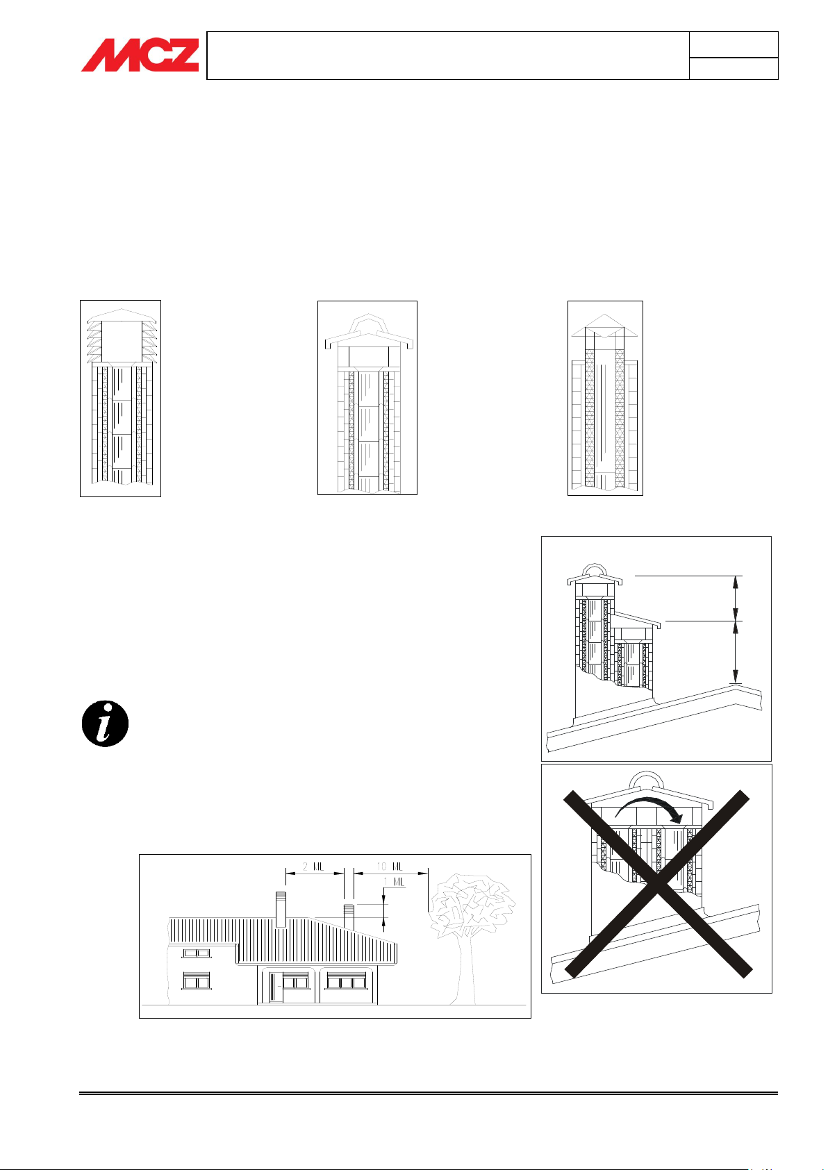
For paired flue pipes, the cowl for solid combustion
and the one for the upper floor must be at least 50cm
higher than the other to avoid pressure transfers
between paired flues.
The cowl must not have obstacles within 10 m such as
walls, roof slopes and trees. Otherwise, raise it at least
1 m over the obstacle and, in the event of other nearby
cowls, keep them at least 2 m away. In any case, the
cowl must exceed the peak of the roof by at least 1m.
An industrial cowl,
with prefabricated
sections fitting
together, allows
optimal disposal of
the flue gases.
A traditional
handmade cowl.
The right exhaust
section must be at
least twice the
internal section of
the flue pipe, 2.5
times is ideal.
Steel cowl for flue pipe
with internal smoke
deflector cone.
1
m
t
0
,
5
m
t
2.6. COWL
If underestimated, it is a severe impediment to correct "chimney
system" operations.
Flue pipe draught also depends on its cowl.
Therefore, if hand made, its four exhaust sections must correspond to
more than twice the internal section of the flue pipe.
Having to exceed the peak of the roof, the cowl will be exposed
to wind, therefore an industrial type is recommended.
The cowl must meet the following requisites:
It must have an internal section equal to that of the chimney.
It must have a useful output section not less that double that
of the internal section of the flue pipe.
It must be built to prevent rain, snow and any foreign objects
from getting into the flue pipe.
They must be installed to guarantee adequate smoke
dispersion and out of the reflux area where negative pressure
forms.
INSTALLATION AND USE MANUAL
Chapter 4
page 12
Installation and assembly
Technical service – MCZ S.p.A. all rights reserved - Reproduction prohibited
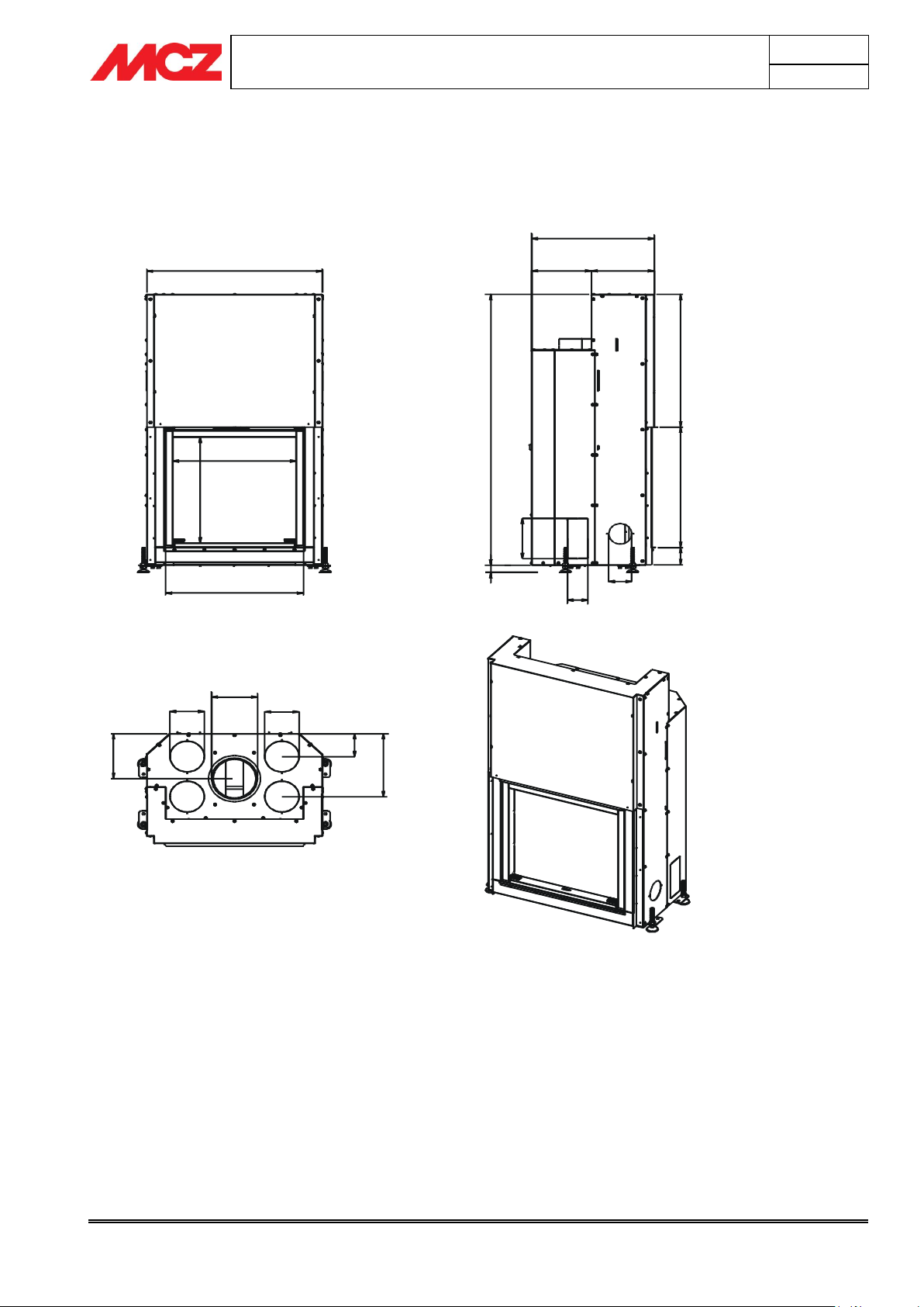
766
538
5
1
6
602
534
260 274
6
4
6
1
3
1
9
5
8
6
.
5
83.5
100
90
35
1
9
5
2
1
9
3
0
6
.
5
150
150
200
1
1
1
.
5
3. DIMENSIONS AND TECHNICAL SPECIFICATIONS
3.1. Dimensions of the Forma Wood 65
INSTALLATION AND USE MANUAL
Chapter 4
page 13
Installation and assembly
Technical service – MCZ S.p.A. all rights reserved - Reproduction prohibited
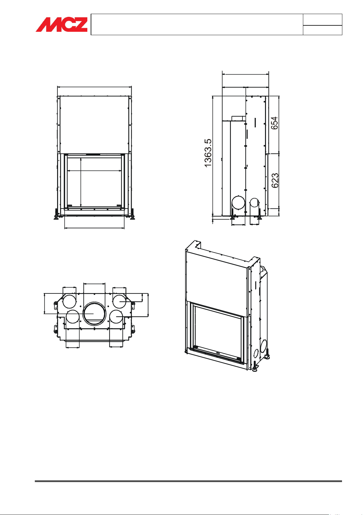
846
618
5
5
3
682
532
263
269
83.5
100
150
3
5
150
2
6
3
.
8
9
3
.
8
250
150
150
150
2
3
1
.
5
3.2. Dimensions of the Forma Wood 75
INSTALLATION AND USE MANUAL
Chapter 4
page 14
Installation and assembly
Technical service – MCZ S.p.A. all rights reserved - Reproduction prohibited
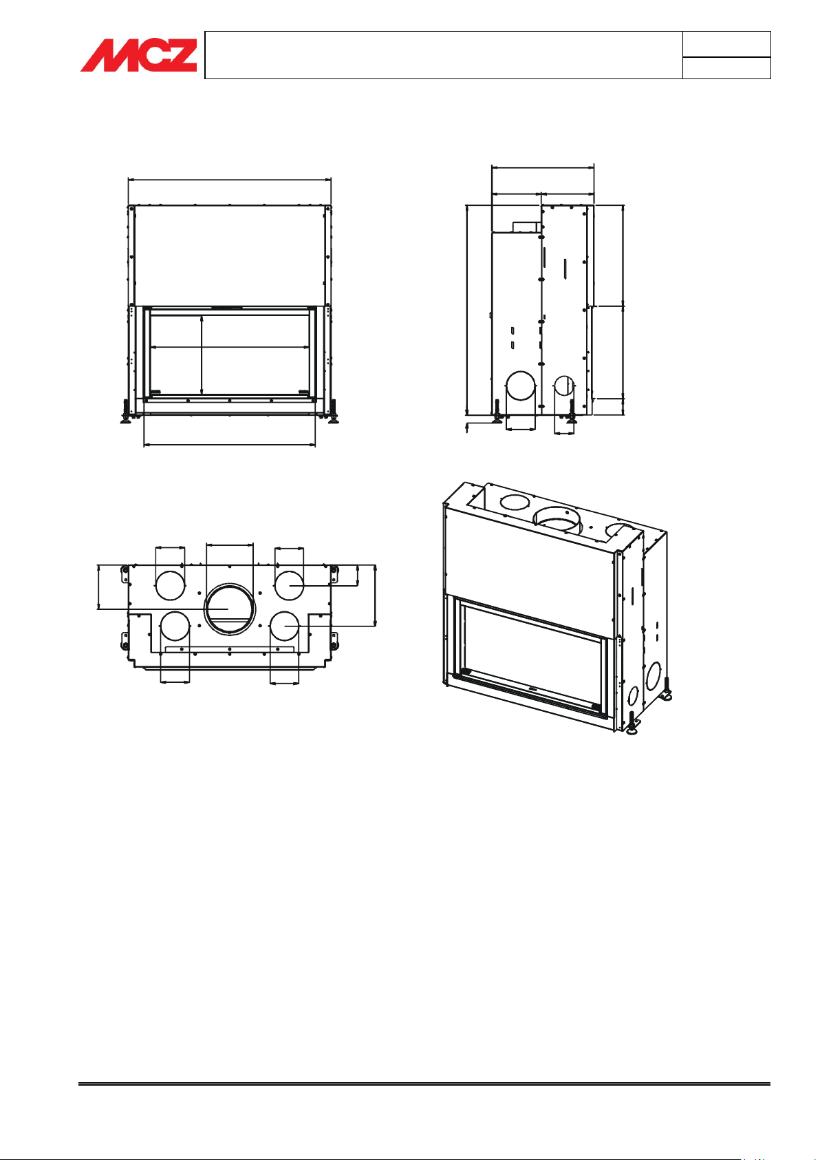
1056
828
4
1
1
892
532
256.5
275.5
5
2
4
.
5
4
8
2
83.5
100
150
35
150
250
150
2
3
1
.
5
150
150
3
1
8
.
8
1
0
8
.
8
1
0
9
3
3.3. Dimensions of the Forma Wood 95

INSTALLATION AND USE MANUAL
Chapter 4
page 15
Installation and assembly
Technical service – MCZ S.p.A. all rights reserved - Reproduction prohibited
1056
828
4
1
1
892
243 250
218
2
5
9
3
1
9
.
5
1
3
5
3
4
5
RETRO
FRONTE
578.5
5
2
6
.
5
4
8
2
100
150
83.5
35
4
8
2
83.5
3
8
4
1
0
9
5
150
3.4. Dimensions of the Forma Wood B95

INSTALLATION AND USE MANUAL
Chapter 4
page 16
Installation and assembly
Technical service – MCZ S.p.A. all rights reserved - Reproduction prohibited
1280
412
1048
1112
532
285.5
246.5
5
2
4
.
5
4
8
2
8
3
.
5
1
0
9
3
35
150
100
150
250
150
150
150
2
3
1
.
5
3
0
8
.
7
5
1
2
8
.
7
5
3.5. Dimensions of the Forma Wood 115

INSTALLATION AND USE MANUAL
Chapter 4
page 17
Installation and assembly
Technical service – MCZ S.p.A. all rights reserved - Reproduction prohibited
Technical specifications
FORMA WOOD 65
Fuel type
Wood
Hourly consumption
2,9 kg/h – 1,2 kg/h
Reloading/load time
50 min / 2,4 kg
Nominal output power
10,5 kW (9030 Kcal/h)
Minimum output power
5,1 kW (4386 Kcal/h)
Efficiency
83,4%
CO emission in the smoke (13% O2)
0,12 %
Particulate/OGC/Nox (13%O2)
39 mg/Nm3-84 mg/Nm3-143 mg/Nm3
Smoke flow rate
13,5 g/s
Smoke temperature
260 °C
Recommended draught
0,12 mbar – 12 Pa
Heatable volume m3
226/40-258/35-301/30*
Smoke outlet
Ø 20 cm
Firebox dimensions
55x35 h59
Net weight
235 Kg
External combustion air inlet
cm² 150
Flue Pipe
Up to 5 m.
30x30 cm diameter 30
Over 5 m.
25x25 cm diameter 25
Notes
Intermittent combustion appliance
* These data may vary according to the type of fuel used
Technical specifications
FORMA WOOD 75
Fuel type
Wood
Hourly consumption
3,1 kg/h – 1,2 kg/h
Reloading/load time
50 min / 2,6 kg
Nominal output power
11,1 kW (9546 Kcal/h)
Minimum output power
5,1 kW (4386 Kcal/h)
Efficiency
83,4%
CO emission in the smoke (13% O2)
0,12 %
Particulate/OGC/Nox (13%O2)
39 mg/Nm3-84 mg/Nm3-143 mg/Nm3
Smoke flow rate
13,5 g/s
Smoke temperature
270 °C
Recommended draught
0,12 mbar – 12 Pa
Heatable volume m3
239/40-273/35-318/30*
Smoke outlet
Ø 25 cm
Firebox dimensions
63x35 h62
Net weight
248 Kg
External combustion air inlet
cm² 150
Flue Pipe
Up to 5 m.
30x30 cm diameter 30
Over 5 m.
25x25 cm diameter 25
Notes
Intermittent combustion appliance
* These data may vary according to the type of fuel used
3.6. Technical specifications
Tested according to EN 13229 in accordance with Directive 89/106/EC (Construction Products).
Tested according to EN 13229 in accordance with Directive 89/106/EC (Construction Products).

INSTALLATION AND USE MANUAL
Chapter 4
page 18
Installation and assembly
Technical service – MCZ S.p.A. all rights reserved - Reproduction prohibited
Technical specifications
FORMA WOOD 95
Fuel type
Wood
Hourly consumption
3,2 kg/h – 1,5 kg/h
Reloading/load time
50 min / 2,7 kg
Nominal output power
12,3 kW (10578 Kcal/h)
Minimum output power
6,7 kW (5762 Kcal/h)
Efficiency
86,6%
CO emission in the smoke (13% O2)
0,12 %
Particulate/OGC/Nox (13%O2)
32 mg/Nm3-54 mg/Nm3-120 mg/Nm3
Smoke flow rate
13,7 g/s
Smoke temperature
280 °C
Recommended draught
0,12 mbar – 12 Pa
Heatable volume m3
264/40-302/35-353/30*
Smoke outlet
Ø 25 cm
Firebox dimensions
84x35 h48
Net weight
268 Kg
External combustion air inlet
cm² 150
Flue Pipe
Up to 5 m.
30x30 cm diameter 30
Over 5 m.
25x25 cm diameter 25
Notes
Intermittent combustion appliance
* These data may vary according to the type of fuel used
Technical specifications
FORMA WOOD B95
Fuel type
Wood
Hourly consumption
3,0 kg/h
Reloading/load time
50 min / 2,5 kg
Nominal output power
10,2 kW (8772 Kcal/h)
Minimum output power
5 kW (4300 Kcal/h)
Efficiency
83%
CO emission in the smoke (13% O2)
0,23 %
Particulate/OGC/Nox (13%O2)
36 mg/Nm3-140 mg/Nm3-128 mg/Nm3
Smoke flow rate
13,7 g/s
Smoke temperature
260 °C
Recommended draught
0,12 mbar – 12 Pa
Heatable volume m3
219/40-251/35-292/30*
Smoke outlet
Ø 25 cm
Firebox dimensions
84x35 h48
Net weight
268 Kg
External combustion air inlet
cm² 150
Flue Pipe
Up to 5 m.
30x30 cm diameter 30
Over 5 m.
25x25 cm diameter 25
Notes
Intermittent combustion appliance
* These data may vary according to the type of fuel used
Tested according to EN 13229 in accordance with Directive 89/106/EC (Construction Products).
Tested according to EN 13229 in accordance with Directive 89/106/EC (Construction Products).

INSTALLATION AND USE MANUAL
Chapter 4
page 19
Installation and assembly
Technical service – MCZ S.p.A. all rights reserved - Reproduction prohibited
Technical specifications
FORMA WOOD 115
Fuel type
Wood
Hourly consumption
3,6 kg/h – 1,5 kg/h
Reloading/load time
50 min / 3 kg
Nominal output power
13,5 kW (11610 Kcal/h)
Minimum output power
6,7 kW (5762 Kcal/h)
Efficiency
86,6%
CO emission in the smoke (13% O2)
0,12%
Particulate/OGC/Nox (13%O2)
32 mg/Nm3-54 mg/Nm3-120 mg/Nm3
Smoke flow rate
13,7 g/s
Smoke temperature
290 °C
Recommended draught
0,12 mbar – 12 Pa
Heatable volume m3
290/40-332/35-387/30*
Smoke outlet
Ø 25 cm
Firebox dimensions
106x35 h48
Net weight
308 Kg
External combustion air inlet
cm² 150
Flue Pipe
Up to 5 m.
30x30 cm diameter 30
Over 5 m.
25x25 cm diameter 25
Notes
Intermittent combustion appliance
* These data may vary according to the type of fuel used
Testata secondo EN 13229 in accordo con la direttiva 89/106/CE (Prodotti da costruzione)

INSTALLATION AND USE MANUAL
Chapter 4
page 20
Installation and assembly
Technical service – MCZ S.p.A. all rights reserved - Reproduction prohibited
IMPORTANT!
The fireplace stove must be installed and connected
to the smoke duct only by a specialized technician, so
that all local and national regulations are complied
with.
Installation must in any case by carried out in
compliance with UNI 10683.
The fireplace stove must always be kept VERTICAL
while moving and only using hand trucks. Do not drag
the unit as this may damage the support feet.
IMPORTANT!
Before installation you will need to decide which
system to adopt.
Example of fireplace stove packing
4. INSTALLATION AND ASSEMBLY
When the fireplace is unpacked, check for perfect operation of all
its parts or any damage which may have occurred during
shipping. The retailer or the carrier must be immediately
informed of any damage.
If the fireplace stove is installed in a place that is difficult to reach, its
weight can be reduced by removing the internal parts that make up the
fire box. However, be sure to put all of the parts back in place.
This operation is to be carried out only by specialized
personnel.
MCZ shall not be held liable if the preceding warning is not
complied with.
4.1. PREPARATION AND UNPACKING
Open the packaging, remove the stove unit from the pallet and position
it in the chosen location, taking care that its position complies with the
above instructions.
Be especially careful that the door and its glass are protected from
mechanical collisions that could jeopardise their integrity.
Moving the product must be done with care. If possible, unpack the
fireplace stove in the area where it is to be installed.
The materials which make up the packaging are not toxic or harmful, so
no special procedures for disposal are required.
The final user must store, dispose or recycle packaging material in
accordance with local regulations.
4.2. SELECTION OF OPERATING MODE
FORMA can distribute hot air either by NATURAL CONVECTION (VN)
or by FORCED CONVECTION (VF) through the use a forced
ventilation.

INSTALLATION AND USE MANUAL
Chapter 4
page 21
Installation and assembly
Technical service – MCZ S.p.A. all rights reserved - Reproduction prohibited
Remove the screws that hold the counterweights only
after you have positioned the fireplace stove and to
ensure that the glass is in good condition.
DO NOT MOVE THE FIREPLACE STOVE WITHOUT THE
SCREWS THAT HOLD THE COUNTERWEIGHTS.
Damage caused by failure to observe this rule is the
responsibility of the client or his representative.
Figure 3a – Distance of unit from walls and from
cladding
Figure 2 – Screw to hold counterweights
Figure 1 – Forma Line knockout panels
5 cm
min.
5 cm
min.
1 cm
4.2.1. Natural convection (VN)
If it is decided to opt for this system, the knockout panels in the
sides and on the back of the unit (as shown in
figure 1
) must be
removed in order to facilitate heat exchange and air circulation.
The upper knockout panels are circular, Ø 150 mm. At least two of
them should be opened and ducted for correct distribution of warm air.
To open the knockout panels, hit them with a rubber mallet and remove
the profile that detaches from the unit.
4.2.2. Forced convection (VF)
If you adopt this system, purchase the optional Comfort Air kit and
follow the instructions in
paragraph 5.3 “Installation of comfort air kit".
4.3. RELEASE OF COUNTERWEIGHTS
The fireplace stove is delivered with the sliding counterweights locked in
place. In this way, during shipping and handling, they will not strike and
damage the sliding parts, the door and the ceramic glass.
To release the counterweights and therefore also the door, remove the
screws as shown in
figure 2
from both sides of the fireplace stove.
4.4. POSITIONING
The FORMA fireplace stove can be placed in a corner or along a wall.
You can customize with MCZ claddings or install them during
construction with materials that are resistant to high temperatures.
The fireplace stoves are self-supporting single-piece units that simplify
installation and do not require any additional support.
To make it easier to move the unit to its place of installation, MCZ
provides four swivel castors that make moving the fireplace stove easy
and convenient.
The four castors, which you will find in the fire mouth along with the
rest of the equipment, are to be installed in the provided holes, located
near the holes for the adjustment feet (figure 3b). Once the fireplace
stove is in place, the castors must be raised off the ground or removed,
so that the unit is stable on the floor.
Always evaluate the structural condition of the surface which
will take the weight, and always leave a minimum 5 cm
airspace between the stove and any walls.
Install dry the fire bed of the cladding leaving an opening of 1 cm
for the insulation.
(Figure 3a)

INSTALLATION AND USE MANUAL
Chapter 4
page 22
Installation and assembly
Technical service – MCZ S.p.A. all rights reserved - Reproduction prohibited
If the stove is positioned over a floor or close to walls
made of flammable materials, it is advisable to use
sufficient insulation.
The hot air outlets must be placed at least 300 mm
from other materials. (e.g. curtains)
The levelling of the fireplace stove is essential so that
the fire door slides correctly.
If the floor is made of flammable material, the lower
part of the fireplace stove must be kept at least 8 cm
from the floor.
If the fireplace stove is not placed level, there is the
risk that door will not close perfectly, and that the
internal counterweights strike the structure, causing
noise each time the door is raised or lowered.
CHECK THAT THE DOOR MOVES CORRECTLY SEVERAL
TIMES BEFORE ENCLOSING THE FIREPLACE STOVE
IN THE CLADDING.
Figure 3b – Points of installation of castors and
feet
A
A
A
B
Figure 3c – Safe distances
For installation near flammable material, comply with the
following minimum safe distances: (Figure 3c)
A = 100 mm (distance from the sides and back)
B = 80 mm (height above floor)
4.5. ADJUSTMENT OF HEIGHT AND BALANCING
The Forma Wood fireplace stove is provided with adjustment feet that
are to be screwed into the unit after you have decided its exact
position. Their purpose is to distance the stove unit from the floor and
to level the fire bed of the fireplace stove. They allow adjustment of
about 10 cm.
If you want to raise the fireplace stove more than 4 cm, you need to
create a masonry pedestal to set the product on. Do not eliminate
the feet. They are indispensable for levelling. Removing the
feet is considered a structural modification of the product and
therefore voids the guarantee.
In the VF forced ventilation configuration (i.e. with fan), you will need
to add the legs in the kit. Their purpose is to raise the fireplace stove as
shown in
feet to adjust the level as described previously.
figure 5b.
On the legs, you will need to install the provided

INSTALLATION AND USE MANUAL
Chapter 4
page 23
Installation and assembly
Technical service – MCZ S.p.A. all rights reserved - Reproduction prohibited
NEVER CLOSE OFF THE COMBUSTION AIR INTAKE
HOLES.
WHEN INSTALLING THE CLADDING, MAKE SURE
THAT NONE OF ITS PARTS OBSTRUCT THE AIR
INTAKES
CONNECT AT LEAST ONE OF THE TWO DUCTS AND
ALWAYS RUN IT OUTSIDE THE CLADDING OF THE
FIREPLACE STOVE. IF YOU DO NOT COMPLY WITH
THIS RULE, THE COMFORT AIR KIT MAY DRAW IN
THE AIR INTENDED FOR COMBUSTION
Figure 5 – Intake for external combustion air
and for natural ventilation
Figure 6 – Air intakes for ducts of fan and
combustion air intake.
Air intake of 300 cm2 for
combustion air and natural
convection
Internal and external air
intakes of 150 cm
2
for
forced ventilation air.
Combustion air intake of
150 cm2
Figure 4 – Combustion air intakes.
A
B
4.6. EXTERNAL AND INTERNAL AIR INTAKE
4.6.1. Combustion air inlet
The FORMA fireplace stove is set up with two side holes Ø 100 mm,
already opened, for the entry of air required for combustion.
Connect by flanges ø100 and hose at least one of the combustion air
inlets (fig. 4) grilles inside or outside the room of installation so that the
path is separate from the air of natural or forced convection.
4.6.2. Air inlet for natural ventilation
If the fireplace stove is installed with natural ventilation, i.e. with no
electric fan, make an external combustion air intake of 300 cm² net
behind the unit so that fresh air always flows beneath the fireplace
stove.
(figure 5)
You must comply with this instruction fully, because otherwise a lack of
oxygen may compromise combustion and calorific energy of the
product.
4.6.3. Air inlet for forced ventilation
4.6.3.1.
If the fireplace stove is installed with forced ventilation, i.e. using the
Comfort Air kit, place air intakes and ducts as follows:
for proper air circulation in the room, it is advisable to arrange one
external air intake A of 150 cm², in order to draw in clean, fresh
air; place the other B in the room where the fireplace stove is
installed (also of 150 cm²).
This mode allows a proper mix of the air in the room of installation
and better cooling of the structure of the fireplace stove.
If you cannot make this kind of connection, you will still need to arrange
both air intakes, whether they are both directed to the exterior or the
interior. Depending on the selection, you will have operating
temperatures that are slightly above or below average but which do not
compromise proper operation of the product.
Ducts for kit COMFORT AIR
(Figure 6)

INSTALLATION AND USE MANUAL
Chapter 4
page 24
Installation and assembly
Technical service – MCZ S.p.A. all rights reserved - Reproduction prohibited
Any increase in the section of the connecting pipe
must start immediately above the hood of the
fireplace and not along the flue pipe section
When installation is complete, the smoke connection
must be insulated with ceramic fibre matting or
material that is resistant up to at least 600°C.
BEFORE YOU START INSTALLING THE CLADDING OF
THE FIREPLACE STOVE, READ CHAPTER 6.2
“OPERATING TEST”
THERMAL PROTECTION OF CROSSBEAM
1. Insulation applied or to be applied.
2. Wood beam
3. Marble or other material
1
1
2
3
10 mm
Figure 7 – Connection to the flue pipe
Figure 8 – Insulating a wooden beam
Remember that:
All of the air intakes must be equipped with shutters than can
be controlled from the outside and that are equipped with
insect protection.
The air intake section is considered net, therefore the area of
any obstructions must be considered (mesh, etc.)
The filters or meshes need to be cleaned periodically to ensure
air can pass through them.
Do not for any reason obstruct the air intakes if the fireplace
stove or ventilation kit is in operation
4.7. CONNECTION TO THE FLUE PIPE
We recommend connecting the stove to the flue pipe by means of pipes
and bends in aluminised steel, capable of withstanding the high
temperatures which are reached in that section of pipe, and of resisting
corrosion from the fumes. These connecting pipes are available on
request in various sizes (see our price list), and they simplify
installation, as they are assembled by fitting one into another.
(figure 7)
4.8. INSTALLATION OF CLADDING AND HOOD
LINER
The fireplace stove and the parts of the cladding must be attached to
one another WITHOUT COMING INTO CONTACT WITH THE
STEEL STRUCTURE to prevent transmission of the heat to the marble
and/or stone, and to allow normal thermal dilation. Use care with wood
finsihes such as crossbeams or shelves.
We recommend making the hood liner in fire-resistant
plasterboard of 15/20 mm thickness, with a self-supporting frame in
galvanised profile, so as not put weight on components of the cladding
(such as wooden beams and marble architraves) which do not have a
load-bearing structure and to make it easy to work in the event of
future anomalies and/or maintenance.
Dry install the fire bed of the cladding, leaving an aperture of 1 cm
between the fireplace stove and the fire bed to provide insulation.
(figure 8)

INSTALLATION AND USE MANUAL
Chapter 4
page 25
Installation and assembly
Technical service – MCZ S.p.A. all rights reserved - Reproduction prohibited
You must install MCZ ventilation nozzles, or nozzles
that ensure the same operation and the same air
passage cross section (see MCZ accessories).
MCZ non risponde di eventuali danni alla struttura o
alla componentistica elettrica causati dalla mancata
osservanza di questa avvertenza.
Figure 9 – Insulation of unit from walls and
from cladding
1a
1b
4.9. INSULATING A WOODEN BEAM
The wood beam must be protected with adequate insulation
from heated parts to prevent the risk of fire or damage of the
cladding.
(figure 8)
4.10. INSULATION OF FIREPLACE STOVE
The fireplace stove must also always be separated from nearby
walls and ceilings.
If necessary, use insulating materials to insulate the walls that are in
contact with the unit if they may be damaged or catch fire (walls made
of wood, plasterboard, etc.).
(figure 9)
4.10.1. Hood ventilation nozzles.
For proper operation of room ventilation remember that:
In the lower part of the cladding, an opening for the entry of
convective air must be provided that is not smaller than 400
cm2
In the upper part it is necessary to provide a vent opening (in
addition to the ducted air outlets) of at least 230 cm2 to release
into the room the residual heat that accumulates inside the
cladding. With the COMFORT AIR kit, however, this outlet is not
necessary, because the heat in the cladding is indirectly drawn
in by the fans.
Besides ensuring perfect product operation, this action makes it possible
to recover part of the heat from the structure, which would be wasted if
it were left inside the cladding.
For better understanding of the number, size and function of the
ventilation nozzles to be installed on the cladding, the following are
some possible installation configurations with the relative nozzles.
1a) Grille for convection air outlet
1b) Grille for intake of convection air
Grilles 1a and 1b are essential for releasing the heat that builds
up in the hood. They must be installed, regardless of the type
of installation or cladding to be realized.

INSTALLATION AND USE MANUAL
Chapter 5
page 26
Comfort air kit
Technical service – MCZ S.p.A. all rights reserved - Reproduction prohibited
1
2
4
3
5
1. Structure of basic natural ventilation outlet (2
pieces)
2. Fastening bracket group (2 pieces)
3. Hose Ø 150 L=1.5 m (2 pieces)
4. Flange Ø 150 (2 pieces)
5. Hose clamp D.60-170 (4 pcs.)
1
2
3
4
5
6
1. Outlet structure with fan with and without
lighting (2 pieces)
2. Fastening bracket group (2 pieces)
3. Hose Ø 100 L=1.5 m (2 pieces)
4. Flange Ø 100 VF (2 pieces)
5. Hose clamp D.60-170 (4 pieces)
6. Control unit
5. COMFORT AIR KIT– NATURAL VENTILATION AND FORCED
VENTILATION
5.1.1. Components of natural ventilation kit with and without illumination
5.1.2. Components of forced ventilation kit with and without illumination

INSTALLATION AND USE MANUAL
Chapter 5
page 27
Comfort air kit
Technical service – MCZ S.p.A. all rights reserved - Reproduction prohibited
A
C
D
B
E
5.2. ACCESSORIES
5.2.1. Air outlets of natural ventilation kit with and without illumination
A – One-direction air outlet without illumination (includes container for dehumidification)
B – One-direction air outlet with illumination (includes light and container)
C – Two-direction air outlet
D – Multi-direction air outlet
E - Natural ventilation air outlet structure for illumination + Fastening bracket group (2 pieces)

INSTALLATION AND USE MANUAL
Chapter 5
page 28
Comfort air kit
Technical service – MCZ S.p.A. all rights reserved - Reproduction prohibited
B
C
D
A
5.2.2. Air outlets for forced ventilation kit
A – One-direction air outlet (includes container/without illumination)
B – One-direction air outlet (includes container and illumination)
C – Two-direction air outlet
D – Multi-direction air outlet

INSTALLATION AND USE MANUAL
Chapter 5
page 29
Comfort air kit
Technical service – MCZ S.p.A. all rights reserved - Reproduction prohibited
Figure 2– Kit installation
Figure 1– Hose connection
a
b
d
c
f
g
e
1
2
2 ml minimo
Figure 3 – Installation of hot air outlets
P
A
5.3. INSTALLATION OF THE COMFORT AIR KIT
Before installing the natural or forced ventilation COMFORT AIR kit,
make sure you have the following material available (fig.1):
1. For natural ventilation: connect the hoses (a) and the
flanges (d) Ø 150 to the connections on the upper part of the
stove unit (fig.1).
For forced ventilation: connect the flanges (d) and the hoses
(a) Ø 100 to the connections on the upper part of the stove
unit. Forced ventilation uses hoses with a smaller diameter than
those used for natural ventilation.
2. prepare on the wall (f) at the desired height two holes for the
hot air outlets measuring 185 mm x 185 mm
3. Insert the structure of the selected outlet (g) in the holes of
185 x 185 mm, working from the outside towards the inside of
the wall
4. on the inner part of the wall, at the structure of the air outlet
(1), attach the fastening bracket group (2), using the four
screws and nuts provided (fig.2)
5. connect the hose (a), previously fastened to the fireplace hose,
to the connection located on the structure of the air outlet (e)
6. tighten the hose (a) on the connection (e) with the provided
clamp (c)
7. before the cladding is complete connect the electrical
cables of the light and/or fan, since everything to be done
afterwards can be done form the outside.
If limitations of space make it impossible to use the bracket provided,
proceed in any case so that the kit is firmly fastened, using the recessed
box (optional).
It is advisable to:
Limit the ducting to 2 linear metres for natural
ventilation, and 8 linear metres for forced ventilation.
For natural ventilation, it is advisable to position the air outlets
at a height of not less than 2 m above the floor. (fig.3).
For forced ventilation, the kit can also be positioned at a
certain distance from the fireplace stove (max 8 m). In this case,
you must properly insulate the ducts so that the heat is not
dispersed and heats only the masonry.
If possible, provide ducts of the same distance to prevent
different quantities of air at different outlets.
For both natural and forced ventilation, it is advisable to
duct the front air outlets (A) where more heat
accumulates than at the rear outlets (P).

INSTALLATION AND USE MANUAL
Chapter 5
page 30
Comfort air kit
Technical service – MCZ S.p.A. all rights reserved - Reproduction prohibited
IMPORTANT!
EXTRACT THE CONTAINER FROM ITS SEAT FOR
FILLING ONLY WHEN THE AIR OUTLET IS COOL AND
THE STOVE UNIT IS OFF.
IMPORTANT!
The cable for the connection of the light/fan is made of
silicone material to withstand high temperatures. If
you use extension cords (over 2.5 m) or in any other
circumstance, make sure that the cord does not come
into contact with the hot parts of the stove and of the
air connection hoses in the cladding of the structure.
If you install the comfort air kit with illumination, it is
necessary to pre-install the light on the kit before
inserting it in the hole.
Figure 5– Knockout for insertion of light
Figure 7-Lamp electrical connections
Figure 6– Fastening the light
Figure 4– Container
1
2
a
b
c
d
5.3.1. Variation for air outlet with container
The essence container (2) is available only on the one-direction air
outlet with and without light. Its purpose is to humidify the air.
The container (2) can easily be removed from its seat. To do so, lift the
door (1) at the bottom and extract the container (see fig.4).
Place only water in the container. It is possible to add essences to
perfume the room.
5.3.2. Variation for air outlet with illumination
If you decide to install the ventilation kit with illumination, you must
remove the knockout panel located on the structure of the air outlet
(fig.5) and pre-install the light (a).
To open the pre-cut knockout panel, strike it with a rubber mallet.
(fig.5).
Install the light (a) on the structure of the air outlet at the knockout
panel so that it is facing the front of the structure (fig. 6). Fasten the
light using the two brackets (c) with the screws (b) and bolts (d)
provided.
Once you have inserted the light (a), make the electrical connections.
In the rear part, insert the two female terminals on the tips of the light
(fig.7)
For forced ventilation, you will need to connect the power cord of the
light (included) to the control unit in the appropriate terminal. For
natural ventilation, the connection must be made to a wall switch (to
be done by the installer).
The cable provided for connection of the light is 2.5 metres. For
greater lengths you will need to use an extension cord.

INSTALLATION AND USE MANUAL
Chapter 5
page 31
Comfort air kit
Technical service – MCZ S.p.A. all rights reserved - Reproduction prohibited
ATTENZIONE!
DISCONNECT THE 230V POWER CORD BEFORE
PERFORMING ANY MAINTENANCE.
Use only light bulbs that are resistant to high
temperatures, such as those used in kitchen ovens.
IMPORTANT!
When you unscrew the screws to remove the glass,
hold the glass with one hand; otherwise it will fall.
5.3.2.1.
Maintenance of air outlet with illumination
Light bulb replacement
1. remove the air outlet by pressing on its sides
2. unscrew the light bulb that has burned out
3. screw in the new light bulb (15 Watt).
4. re-insert the air outlet
Cleaning glass light fixture of the air outlet
1. Open the door that contains the dehumidification container.
2. Remove the container
3. With the key provided, loosen the two screws, so that the
bracket that supports the glass slides in the slots. Hold the
glass with one and with the other free it from the bracket.
Remove it and clean it.
4. Once you have cleaned the glass, re-insert it in its seat. Secure
it by following the previous steps in reverse order.
5. Put the container and door back in place.

INSTALLATION AND USE MANUAL
Chapter 5
page 32
Comfort air kit
Technical service – MCZ S.p.A. all rights reserved - Reproduction prohibited
IMPORTANT!
All electrical connections must be performed by
qualified personnel in accordance with current laws in
each nation, using suitable equipment and in
compliance with the diagram indicated in this booklet.
All operations must be performed with the 230V 50 Hz
mains power cord disconnected.
Mcz shall not be held liable for damage to persons or
things due to incorrect connections or improper use of
the device.
A
B
C
D
E
F
G
5.4. CONTROL UNIT
5.4.1. Composition of control unit
The following material is provided with the control unit:
A. recessed box
B. Control unit, screws for fastening and power cord
C. Probe and cable clamp
D. Terminal for the common earth cable
E. Spare fuse (1.6 A)
F. Plate
G. Instructions
The control unit is equipped with 6 double terminals for the connection of:
1. Line (1-2 LINEA)
2. Fan 1 (3-4 VENTIL.)
3. Fan 2 (5-6 VENTIL.)
4. Light (7-8 AUX)
5. Switch for door opening (9-10 PORT.)
6. Probe (11-12 SONDA)
5.4.2. Positioning of the control unit
Make a hole in the wall (about 10X7.5 cm) for the installation of the
control unit, taking into account the positioning of the probe.
In this hole, insert the recessed box (A) without the control unit body
(B). Be sure to position it in a dry place, as far as possible from
heat sources, compatible with the position of the probe.
Run the cables (probe, power supply, fan and switch for door opening)
through the recessed box (A) so that they are available for connection.
Connect them to the terminals located on the control unit as shown in
figure 4.14.
Once connections are complete, insert the control unit body and fasten
it with the provided screws to the recessed box (A).
Finally, insert the white plate provided (F) or any other one, since the
control unit body is set up to house AVE SYSTEM 45 series and VIMAR
IDEA series plates using special hooks.

INSTALLATION AND USE MANUAL
Chapter 5
page 33
Comfort air kit
Technical service – MCZ S.p.A. all rights reserved - Reproduction prohibited
2
3
4
4a
5a
4b
1
5
5.5. GENERAL INFORMATION ON THE CONTROL UNIT
1. “ON” –“OFF” indicator light
2. Fan active light
3. Fan speed control knob
4. MAN/AUT button
4a. Automatic
4b. Manual
5. Lamp on button
5a. Lamp on/off
The device makes it possible to control the speed of the fan it is
connected to. The speed is set by turning the knob to 10 speed steps:
0 ,V1; ….. V9, V10.
MANUAL/AUTOMATIC mode is set using button 4.
5.5.1. On/off
The control unit is turned on and off by turning knob 3.
On status is indicated by LED 1.
5.5.2. Operation
Activation of the fan is signalled by LED 2
AUTOMATIC mode (AUT LED on 4a)
The AUT is generally used to turn off the fan.
For example, in the evening you can load wood for the last time
and turn the selector to AUT. The fan, with the consent of the
probe, will continue to provide hot air until the temperature
drops. In this way, you will keep the room comfortable all night
long. The next morning, the fire box will contain embers ready
for a new load of wood or it will be out.

INSTALLATION AND USE MANUAL
Chapter 5
page 34
Comfort air kit
Technical service – MCZ S.p.A. all rights reserved - Reproduction prohibited
IMPORTANT!
All electrical connections must be performed by
qualified personnel in accordance with current laws in
each nation, using suitable equipment and in
compliance with the diagram indicated in this booklet.
All operations must be performed with the 230V 50 Hz
mains power cord disconnected.
Mcz shall not be held liable for damage to persons or
things due to incorrect connections or improper use of
the device.
ON
OFF
MANUAL mode (MAN LED on 4b)
The fan runs at the selected speed independently of the
temperature measured by the sensor. When the stove unit is
turned on, on the control unit place selector 4 in manual 4b.
The speed of the fan is set using the knob (3).
With the knob turned completely to the left, the fan is off as is
the indicator light (1). Turn the knob to the right to change
from “OFF” to “ON” (indicator light 1 on). If you continue
turning the knob to the right, the speed of the fan will gradually
increase (indicator light 2 on).
In manual mode, the fan will operate in a mode regardless of
the probe, and will therefore be controlled by the knob (3)
5.5.3. Safety function
When knob 3 is in the off position, the safety function is active.
If the temperature probe reaches the safety threshold, the fans
come on at minimum speed to prevent overheating of the
structure.
If the safety function trips frequently, contact the technical service
department of MCZ.
5.5.4. Light on (if present)
Press button 5 to turn the light on or off.
The LED 5a indicates the status of the light.
5.5.5. Replacing the fuse of the control unit
The control unit is equipped with a fuse that protects the system
against voltage overloads.
When mains power is provided at 230V-50Hz, if none of the indicator
lights of the control unit come on, the fuse is probably faulty.
To replace it, proceed as follows:
remove the plate that covers the control unit
unscrew the two screws that hold the control unit to the wall
box
carefully extract the body of the control unit
open the plug and replace the faulty fuse with a working one
(about 1 A)

INSTALLATION AND USE MANUAL
Chapter 5
page 35
Comfort air kit
Technical service – MCZ S.p.A. all rights reserved - Reproduction prohibited
IMPORTANT!
Mcz shall not be held liable for smoke coming out of
the air outlets if the switch is not properly connected
to the control unit.
A1
F
B
A1
A
B
C
D
E
F
5.6. INSTALLATION OF TEMPERATURE PROBE
The temperature probe must be connected to the control unit and to
the duct (1) of a kit (see diagram below) and has a length of 2.5 m.
Greater distances require the use of and extension to be provided by
the installer.
PROBE INSTALLATION
Insert the plastic piece C in D and screw in B without forcing it.
On the threaded part of piece D insert washer E
The group thus formed A1 must be inserted on the rigid part of
the cable of probe A
Identify the pass-through hole for insertion of the probe on the
duct (1); on the grille at lower right alongside the fan.
Insert in the hole the cable of probe A with the block A1 and
secure it on the other side with the nut F
Insert the other end of the cable of probe A in the control unit
in the indicated position (12-11)
5.7. DOOR OPEN SWITCH
On fireplace stoves of the “Wood” line, MCZ has installed a switch
which, in the case of forced ventilation, must be connected to terminals
9-10 of the control unit, after removing the connection between the 2
terminals provided by the manufacturer. To this end, place an extension
of adequate length, in silicone material resistant to high temperatures.
Make sure the cable does not come into contact with the hot parts of
the fireplace stove.
This switch disables the fans when the door of the fireplace
stove is opened. This is indicated by the flashing of the fan active
indicator light (LED 2 see chap. 5.5).

INSTALLATION AND USE MANUAL
Chapter 5
page 36
Comfort air kit
Technical service – MCZ S.p.A. all rights reserved - Reproduction prohibited
11-12
A
7-8
7-8
5-6
3-4
5.8. CONNECTIONS
LINE (1-2 LINEA)
FAN 1 (3-4 VENTIL.)
FAN 2 (5-6VENTIL.)
LIGHT (7-8 AUX)
SWITCH FOR DOOR OPENING (9-10 PORT.)
PROBE (11-12 SONDA)
TERMINAL FOR EARTHING (A)
Connect fans 1 and 2 to the corresponding terminals on the control unit
(3-4 and 5-6).
Connect the probe (11-12); see paragraph 5.6.
For air outlet with light, connect the power cord to the control unit on
the terminals (7-8). For air outlets with a light for natural ventilation,
make the connection to a dedicated switch.
Connect the power cord of the control unit (1-2) to the 230V 50HZ
mains socket.
Once the connections have been made, activate MAN operation and
try turning on the fans to see of they all work. Turn the knob right and
left to test the various speeds.
When connections are complete, install the selected air outlets.

INSTALLATION AND USE MANUAL
Chapter 5
page 37
Comfort air kit
Technical service – MCZ S.p.A. all rights reserved - Reproduction prohibited
ATTENTION!
DISCONNECT THE 230 V POWER SUPPLY.
ATTENTION!
WHEN THE CABLES ARE DETACHED, MAKE SURE TO
SECURE THEM.
IF THEY FALL INSIDE THE CLADDING THERE IS NO
WAY TO GET THEM BACK OUT.
IMPORTANT!
THE FAN MUST FACE AS SHOWN IN FIG.9. NO OTHER
POSITIONS THAN THE ONE SHOWN ARE PERMITTED.
IMPORTANT!
All electrical connections must be performed by
qualified personnel in accordance with current laws in
each nation, using suitable equipment and in
compliance with the diagram indicated in this booklet.
All operations must be performed with the 230V 50 Hz
mains power cord disconnected.
Mcz shall not be held liable for damage to persons or
things due to incorrect connections or improper use of
the device
Figure 9– Fan position
A
A
A
A
B
B
C
Figure 8– Fan replacement
5.9. REPLACING THE FAN
Remove the air outlet
Loosen the four screws A that are located on the grille on the
four corners fig. 8
Loosen the two middle screws B that hold the fan to the duct
Extract grille C
Detach the cable of the fan
If the light fixture has a light bulb, disconnect the power cables
when extracting the flange.
It is now sufficient to turn the fan with respect to the duct to
allow passage without damaging the piece.

INSTALLATION AND USE MANUAL
Chapter 6
page 38
Operation
Technical service – MCZ S.p.A. all rights reserved - Reproduction prohibited
Do not touch the fireplace stove when it is lit for the first
time. During this phase, the paint finishes drying and
hardens. If you touch the paint, you may expose the steel
surface.
It is good practice to provide plenty of ventilation in the
room during the initial lighting, as the stove will give off a
small amount of smoke and smell of paint.
If necessary, touch up the paint with the aerosol spray in
the original colour (see “Fireplace stove accessories and
inserts")
It is very important not to bring the stove up to full
heat immediately. Bring it up to temperature
gradually.
This avoids damages to welds and the steel
structure.
Do not demand full heating
performance straight away!
ATTENTION!!
BEFORE PROCEEDING IN ANY WAY WITH THE
INSTALLATION OF THE CLADDING, CARRY OUT A
GENERAL TEST OF THE FIREPLACE STOVE AS
FOLLOWS:
Raise and lower the fire door 7-8 times to ensure
fluid sliding and that the counterweights do not
produce noise when they come into contact with
the structure (if this anomaly occurs, review chapter
7.1.4)
Check that all of the wiring and the control unit (if
the kit COMFORT AIR VF is installed) are always
placed at a distance from the hot body of the
fireplace stove.
Test the ventilation kit at all speeds and in all
modes (if kit COMFORT AIR VF is installed)
Light the fire at low power to ensure the smoke
connections do not leak smoke or soot. Before
lighting, however, read Chapter 6.
6. OPERATION
6.1. PRE-LIGHTING WARNINGS
Do not stay near the fireplace stove, and as previously mentioned,
ventilate the room. The smoke and the smell of paint will vanish after
about one hour of operation. There are no health risks involved.
The fireplace stove will be subject to expansion and contraction during
the stages of lighting and cooling down, and may therefore make slight
creaking noises.
This phenomenon is absolutely normal, the structure being made of
sheet steel, and must not be considered a fault.
6.2. OPERATING TEST

INSTALLATION AND USE MANUAL
Chapter 6
page 39
Operation
Technical service – MCZ S.p.A. all rights reserved - Reproduction prohibited
MCZ SHALL NOT BE HELD LIABLE FOR ANY DAMAGE
WHICH THE CLADDING MAY SUFFER IF THE
AFOREMENTIONED CONTROLS ARE NOT PERFORMED
AND IT BECOMES NECESSARY TO DEMOLISH THE
CLADDING TO PERFORM REPAIRS OR ADJUSTMENTS.
Do not use treated fuels (such as painted or
varnished wood, or particle board) or unsuitable
materials (such as plastics and derivatives), which
could release toxic or polluting substances. Do not
burn rubbish.
The gases produced by combustion due the use of
unsuitable fuels cause damage to the fireplace stove
and the chimney, they cause pollution and can
compromise your health.
Wood drying
time (i.e.
beech)
%
humidity
Heat
power
Kcal/h
Freshly cut
50 / 3 months
40
2410
6 months
35
2700
9 months
30
2900
12 months
25
3150
15 months
20
3400
18 months
15
3710
21 months
10
3980
Figure 11 – Calorific energy (e.g. beech) in
relation to humidity contained.
Figure 10 – Maximum adjustment of
combustion air opening
M
A
X
6.2.1. Phases for first test lighting
Make sure you have read and completely understood the
contents of this instruction booklet.
Remove any components which might burn from the fireplace
stove and door (various instructions and adhesive labels).
Remove the stickers from the ceramic glass or the high
temperature could melt them and irreparably damage the glass.
In this case, the MCZ warranty does not cover the glass.
Completely open the front register of the combustion air using
the provided hook.
Place wood in small pieces that is well dried (humidity 15/20%).
Light the fire at low power without excessively heating the
structure. Any odours from manufacturing residue and/or
evaporation will form the first time lighting occurs, and will
disappear after a lighting at full power has occurred a few times.
6.3. CHOICE OF FUEL
To obtain the maximum performance from your FORMA fireplace stove,
it is of primary importance to use wood with suitable
characteristics.
It is advisable to use wood for heating such as oak, beech, locust
tree, or oak with good calorific energy, or logs of pressed wood that
do not have resin. These have a high calorific power and must
be used with caution to avoid overheating which could damage
the stove.
It is advisable to use fuels such as poplar, pine, lime tree, or
chestnut which have low calorific power, since they are soft wood and
also they do not burn for a long time.
Avoid using fuels such as pine, fir, and olive as they contain a high
degree of resin and their combustion may substantially soil the fire
mouth and the ceramic glass; also, they do not have an exceptional
yield.
For all types of wood listed, the humidity they contain is
essential because it determines the calorific energy.

INSTALLATION AND USE MANUAL
Chapter 6
page 40
Operation
Technical service – MCZ S.p.A. all rights reserved - Reproduction prohibited
A high percentage of humidity produces condensation in the
smoke duct causing an alteration in the draught and
generating smoke and a significant deposit of soot on the
glass of the door and in the flue pipe with a possible risk of a
chimney fire later on.
6.4. FIRST LIGHTING
It is advisable to approach the first lighting with caution, using
good-quality, well-seasoned wood.
The primary air inlet must be fully open. Do not use alcohol,
petrol, or other volatile flammable substances. On first lighting,
fumes and unpleasant smells may be given off, caused by the drying of
the product; this is not hazardous, and it is sufficient to ventilate the
room. Once combustion has started, pieces of wood of normal size may
be added.
The flame must have as far as possible a smooth and laminar flow. On
the various occasions when the stove needs reloading, the door
should be opened slowly, to avoid blowbacks of smoke into the
room.
Proceed as follows:
Place a small amount of balled paper in the stove.
Cover the paper with a small quantity of twigs and a few pieces of
wood.
Open the primary air register completely (lever all the way to the
right).
Light the paper, and if necessary leave the door up.
When the twigs are burning, the door can be closed.
As the fire burns, add wood. Never overload the fireplace stove
with wood (see technical specifications in the table).
As soon as the flames have died down and a bed of embers has
formed, load the stove normally. Small loads of wood are preferable to
large ones for combustion.

INSTALLATION AND USE MANUAL
Chapter 6
page 41
Operation
Technical service – MCZ S.p.A. all rights reserved - Reproduction prohibited
Attention
Do not use volatile, flammable substances
(petrol, alcohol etc.) for lighting the fire.
Do not use fuels which could release toxic
substances or pollutants.
Do not put the fire out by throwing water on it.
Check the external and internal air intakes, and
the flue pipe, at least once a year, arranging for
them to be cleaned.
During use, the metal parts and the glass reach
high temperatures. For all jobs of loading the
stove, adjustment or cleaning the ash drawer,
use the insulating glove provided.
Never leave children unattended near the
fireplace stove when it is in use.
The risk of burns from contact with hot surfaces
is very high.
Nominal combustion has a duration of 50 min. Therefore, to
obtain the nominal hourly loading set forth in the table in
chapter 3, load the amount shown in parentheses in the
table every 50 minutes.
Figure 12 – Opening/closing the fire door
6.5. LOADING THE FUEL
For normal fuel loading, open the fire door by lifting one of the handles
as shown in
figure 12
. To close the door, do the opposite.
During use, the metallic structure, the handles and the glass
become very hot. Use the thermal glove provided when
handling these parts.
During normal use, always keep the fire door completely down
and closed. Intermediate positions cause abnormal combustion (forge
effect), rapid wood consumption, and may cause smoke to leak out due
to the high temperature of the fire box.
Open the door only to add fuel, and only for brief periods of
time.
The fireplace stove works best and provides the greatest yield when the
door is closed, because the hermetic combustion chamber and the
calibrated inlet of oxygen allow increased performance.

INSTALLATION AND USE MANUAL
Chapter 6
page 42
Operation
Technical service – MCZ S.p.A. all rights reserved - Reproduction prohibited
The use of damp or treated wood emits a higher quantity of
smoke than normal that can dirty glass faster. Also the low
performance of the flue pipe can jeopardise glass cleanliness
since smoke remains in the combustion chamber longer than
normal.
Figure 13 – Adjustment of
primary/secondary air.
M
A
X
M
I
N
6.6. CONTROL OF COMBUSTION
PRIMARY AIR
The fireplace stove is equipped with two flanged side holes Ø100 mm
for the inlet of primary air which ensures combustion and helps keep
the glass clean.
. Moving the lever to the left provides the full aperture, and more rapid
combustion, while moving it to the right closes the opening, with slower
burning.
SECONDARY AIR
Adjustment is performed using the same lever as for the primary air.
Secondary air comes out in proportion to the primary air. This balance
is pre-calculated; the user cannot change it, as this may cause incorrect
adjustment. This will prevent excessive combustion.
6.7. EMERGENCY SITUATIONS
If for any reason the stove fire needs to be suddenly and quickly put
out or a fire in the flue pipe needs to be put out, proceed as follows:
If time allows, remove the grate and ashes, using a metal
container.
Put the fire out rapidly by means of a dry carbon dioxide (CO
extinguisher.
2
)

INSTALLATION AND USE MANUAL
Chapter 7
page 43
Maintenance and cleaning
Technical service – MCZ S.p.A. all rights reserved - Reproduction prohibited
ATTENTION!
All cleaning operations of all parts should be
conducted with the fireplace stove cold.
ATTENTION!
Do not spray the product on the painted parts or on
the gaskets of the door (ceramic fibre cord)
Figure 14 – Opening the flap door
A
B
Detail of handle for opening flap door
A – CLOSED POSITION
B – OPEN POSITION
7. MAINTENANCE AND CLEANING
7.1. CLEANING TO BE PERFORMED BY THE USER
7.1.1. Cleaning the glass
Specific products can be used to clean the glass (see our price list), a
cloth dampened with water and ammonia or a bit of white ash and a
newspaper.
To open the flap door (
LOWER THE GLASS and open the flap door as shown in the figure
using the handle. You can open this handle using your hands or with
the hook provided.
To close, perform the steps listed above in reverse order.
figure 14)
to clean the glass, COMPLETELY
7.1.2. Cleaning out the ashes
This must be done when the fireplace stove is off and cold.
It is advisable to adequately clean the fire bed for proper combustion.
To remove the ashes from the fire bed, use a metal scoop and brush.
Place the ashes in a non-flammable container for transport.
Ashes which are still hot must neither be dumped outside in an
uncontrolled manner nor put in the dustbin. Leave them to cool
down in the open air in a metal container.
7.1.3. Cleaning the refractory material walls (ALUTEC
They do not require any cleaning, since the feature of this material
(ALUTEC®) is that it does not absorb soot but rather repels it when the
fire box is hot. During the lighting phase, during which the fire box
tends to blacken, the refractory materials will turn white again, starting
from the base of the flame, when the combustion chamber reaches its
operating temperature (~ 400° C).
If this does not happen, it may be due to the following:
Humid or resinous wood that does not release enough heat or
that dirties the combustion chamber
Flue pipe with poor performance resulting in smoke remaining
too long in combustion chamber, dirtying the fire box.
Flue pipe with poor performance which does not allow fireplace
stove to reach high yield that results in adequate temperature of
the refractory material.
(see chapter 6.3)
®
)

INSTALLATION AND USE MANUAL
Chapter 7
page 44
Maintenance and cleaning
Technical service – MCZ S.p.A. all rights reserved - Reproduction prohibited
Never clean the refractory material with a damp cloth
or anything else, as it may be stained.
Use a dry paintbrush if necessary to remove heavy
soot build-up.
If the Alutec does not whiten, it is not to be
considered as a defect in light of the warnings and
instructions above.
It is advisable to carry out this operation at the end of
the season of use, or whenever the runners become
too noisy.
Do not use other types of grease. If the grease gun
runs out, request an MCZ original replacement.
The maintenance of all electrical parts (fan, control
unit, etc.) must only be carried out with no electrical
power supplied and with the unit unplugged.
Figure 15 – Points to be greased with provided
grease gun
7.1.4. Lubrication and routine maintenance of the
extensible guides
All of the doors of the fireplace stoves are mounted on extensible
ballbearing guides that ensure a robust, sturdy system that provides
silent movement.
Prolonged use and the heat of the fireplace stove gradually depletes the
lubricant in the guides. This will cause them to become less efficient
and noisier.
If necessary, periodically grease both runners as follows:
Pull open the frame liner and extract the door so you can see
the tracks of the guide.
Using the provided grease gun, apply two drops of grease,
about 5 mm in diameter, at the highest visible point of the
runners. Do not exceed the recommended amount!
Perform this operation on both guides. Keep in mind that the
total amount of grease to be used is about 0.5ml (see
graduated scale on grease gun).
After lubrication:
Put the glue gun back and conserve it
Lower and raise the door completely at least 6 or 7 times so
that the grease is spread onto all of the other components of
the guides to complete lubrication. You should notice a
substantial improvement in ease of movement and noise
reduction.
7.1.5. Maintenance of kit VF (if installed)
7.1.5.1.
Periodically, and at least at the end of each winter, it is advisable to
clean the fan blades, which may have suctioned up dust or other small
foreign bodies due to the static pressure exercised by the fan along the
air ducts.
Clean the fan blades only with compressed air or with a vacuum
cleaner. Take care not to damage the rotor or the fan blades.
Electric fan

INSTALLATION AND USE MANUAL
Chapter 7
page 45
Maintenance and cleaning
Technical service – MCZ S.p.A. all rights reserved - Reproduction prohibited
Do not use any sort of rigid device which might bend
the blades. When rotating, bent blades will produce
more noise than normal due to off-axis rotation of
the fan.
7.1.5.2.
Does not require any special maintenance if located as instructed in
chapter 5.4.
the fuse.
7.1.5.3.
Make sure the wiring is in good condition and that it is not near the hot
body of the fireplace stove. Heat may damage it.
Control unit COMFORT AIR
From time to time, you may want to check the condition of
Wiring
7.2. CLEANING TO BE DEALT WITH BY SPECIALIZED
TECHNICIAN
7.2.1. Cleaning flue pipe
Mechanical cleaning of the flue pipe is recommended at least once a
year. Excessive deposits of unburnt solid material can cause problems
with the evacuation of smoke, and gives rise to a risk of chimney fires.
To clean the appliance's chimney, remove the smoke deflector. To
remove it correctly, lift the front and at the same time slide it forward in
order to free it from rear support.

8901155100
Rev. 1
03/2013
MCZ GROUP S.p.A.
Via La Croce n°8
33074 Vigonovo di Fontanafredda (PN) – ITALY
Telephone: +39 0434/599599 PBX
Fax: +39 0434/599598
internet: www.mcz.it
e-mail: mcz@mcz.it
 Loading...