

INSTALLATION GUIDE EN
PELLET STOVE
TOBA HYDRO
HYDRO 22
HYDRO 22 WITH HIGH EFFICIENCY PUMP
HYDRO 22 WITH EXCHANGER
PART 2 - OPERATION AND CLEANING
Instructions in English

TABLE OF CONTENTS
TABLE OF CONTENTS ...................................................................................... II
9 PRECAUTIONS BEFORE STARTUP ................................................................ 3
10 CONTROL PANEL ..................................................................................... 4
11 FIRST STARTUP ...................................................................................... 5
12 MENU STRUCTURE................................................................................... 7
13 MENU INFORMATION ..............................................................................11
14 MENU SETTINGS ....................................................................................14
15 TECHNICAL MENU ..................................................................................32
16 SAFETY DEVICES AND ALARMS .................................................................33
17 RECOMMENDATIONS FOR A SAFE USE ........................................................38
18 MAINTENANCE AND CLEANING .................................................................39
19FAULTS/CAUSES/SOLUTIONS .....................................................................47
20 CIRCUIT BOARD .....................................................................................50
II
9 - PRECAUTIONS BEFORE START-UP
GENERAL PRECAUTIONS
Remove any objects that may burn from the brazier (manual, various adhesive labels or any remaining polystyrene).
Check that the brazier is positioned correctly and rests properly on the base.
The rst start-up may not be successful as the feed screw is empty and does not always manage to load the required
amount of pellets in time to light the ame.
CANCEL THE ALARM FOR THE LIGHTING FAILURE BY HOLDING DOWN BUTTON 1 (ESC). REMOVE THE PELLET LEFT IN THE
BRAZIER AND REPEAT THE START-UP.
If after repeated attempts, the ame fails to ignite, despite a regular ow of pellets in the brazier, check that the brazier is seated correctly:
it must rest snugly against the slots and be clean of any ash incrustations. If no anomaly is found during this inspection, there
may be a problem with the product components or installation may not be correct.
REMOVE THE PELLETS FROM THE BRAZIER AND CONTACT AN AUTHORISED TECHNICIAN.
Do not touch the boiler during the rst lighting, as it is during this phase that the paint sets.
If necessary, touch up the paint with the aerosol spray in the original colour (see ''Accessories for pellet stoves'').
It is good practice to ensure eective ventilation in the room during the initial start-up, as the boiler will emit some
smoke and smell of paint.
ATTENTION!
Please ensure the brazier is clear of ALL pellets and ash build up following any failed ignitions. Failure to clear out
the brazier prior to resetting may result in further failed ignitions or in certain conditions an explosive ignition.
Do not stand close to the stove and, as mentioned, air the room. The smoke and smell of paint will disappear after about an hour of
operation, however, they are not harmful in any case.
The boiler will be subject to expansion and contraction during the lighting and cooling down stages, and may therefore make slight
creaking noises.
This is absolutely normal as the structure is made of laminated steel and must not be considered a defect.
It is extremely important to make sure the boiler does not reach high temperatures straight away, but to increase the temperature
gradually using low power at rst.
This will prevent damaging the ceramic or serpentine stone tiles, the welds and the steel structure.
DO NOT EXPECT HEATING EFFICIENCY IMMEDIATELY!!!
ATTENTION!
If during operation or initial ignition you encounter smoke spillage in to the room from the appliance
or the ue then please switch o the appliance, ventilate the room and contact the installation / service
engineer immediately.
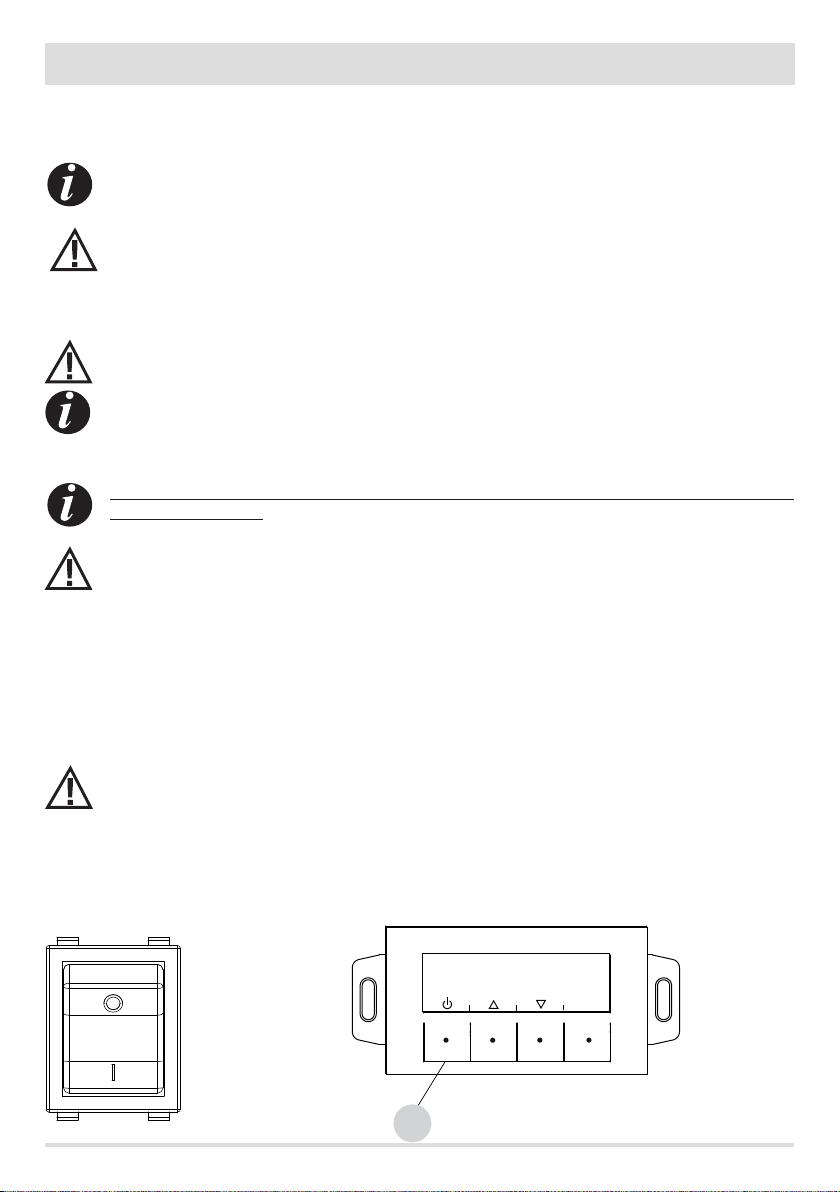
SETTINGS TO BE CARRIED OUT BEFORE THE INITIAL START-UP
After connecting the power cable to the electrical socket, turn the power switch to the (I) position. To turn the stove on or o, press the
button “B” on the control panel.
OFF
ON
Technical Dept. - All rights reserved - Reproduction is prohibited
MENU
B
3
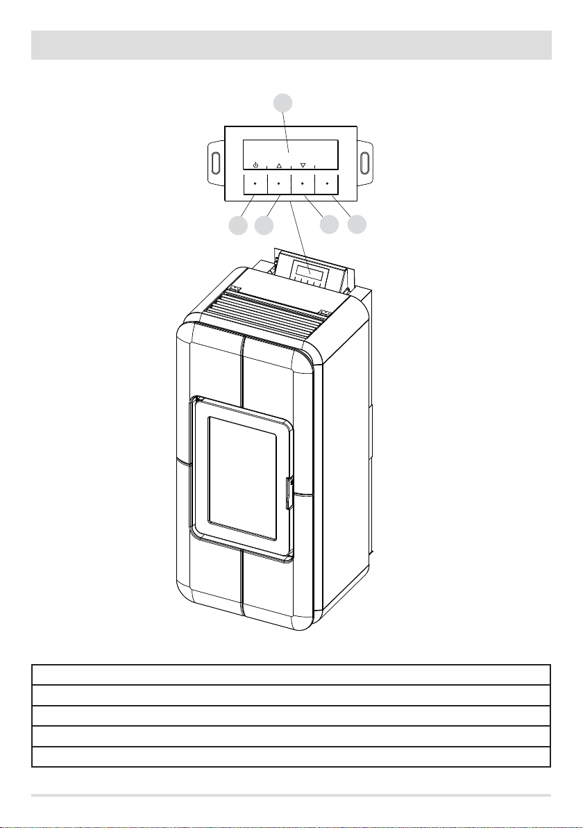
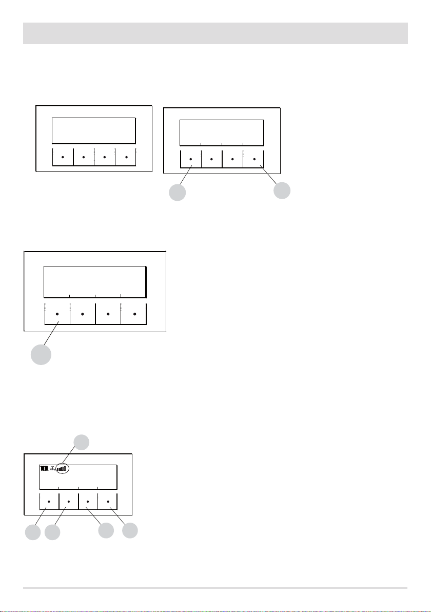
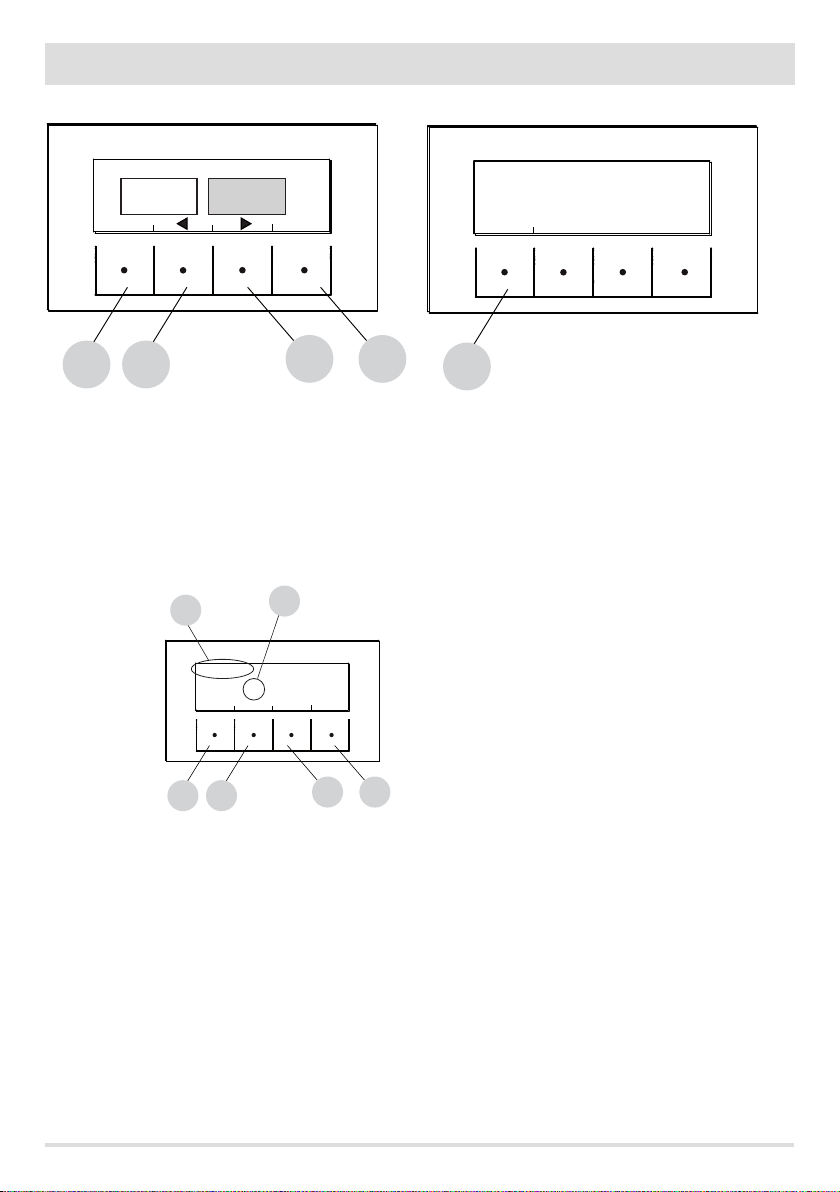
10 - CONTROL PANEL
CONTROL PANEL DISPLAY
B C
A
MENU
E
D
KEY
A - DISPLAY; indicates a series of information on the stove, as well as the identication code of any malfunction.
B - Function selection key indicated by the upper display (i.e. start-up/shutdown)
C - Function selection key indicated by the upper display (i.e. increase/scrolling)
D - Function selection key indicated by the upper display (i.e. decrease/scrolling)
E - Function selection key indicated by the upper display (i.e. menu)
4
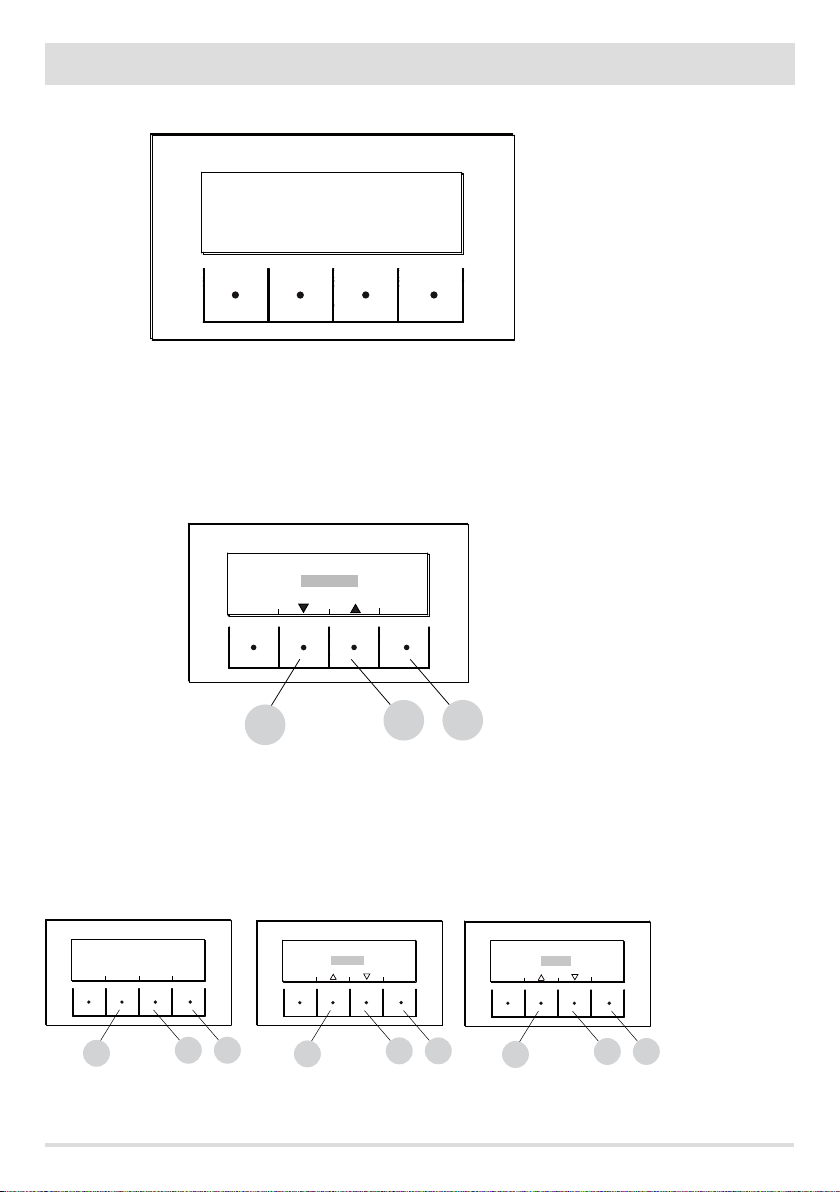
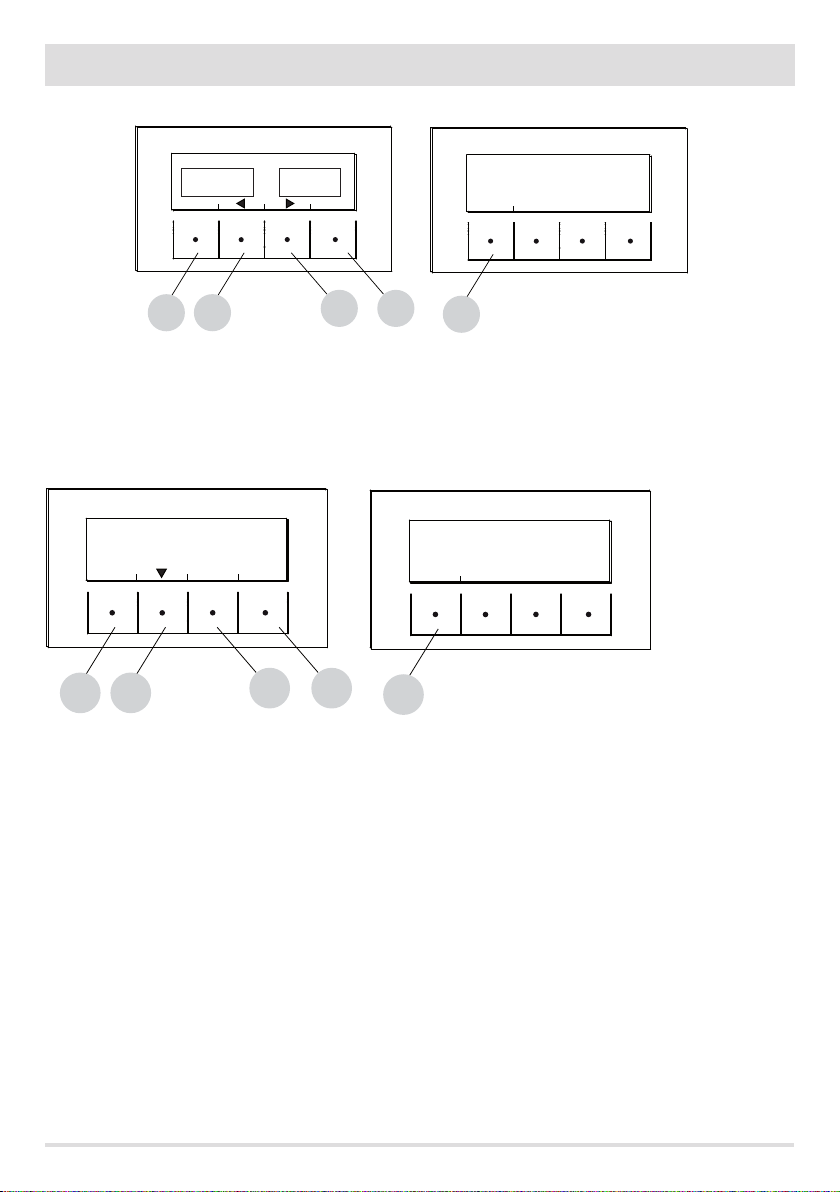
11 - FIRST START-UP
START BUTTON
PRODUCT TYPE VERSION
At initial start-up, after connecting the power cable and pressing the I/O button, the stove display will show wording for the software
version and database number (after a few seconds it will move on to the next screen).
If the language has already been set, the next screen will be OFF, otherwise one enters the following parameter.
SELECT LANGUAGE
At initial start-up, if it has never been set, the LANGUAGE choice screen appears.
LANGUAGE
ITALIANO
ENGLISH
ESPANOL
C
The system displays all possible languages.
Using the arrow keys (C, D) scroll the languages and conrm the desired language using the “E” (OK) key.
OK
D
E
SETTING TIME AND DAY
The keys that are active for this function are: “B”,“C”, “D”, “E”. The C-D keys are used to choose time or day while the E key is used to conrm.
TODAY IS MONDAY AND IT IS
21.25
CHANGE
CHANGE
DAY
C
OK
TIME
E
D
Technical Dept. - All rights reserved - Reproduction is prohibited
TODAY IS MONDAY AND IT IS
21.25
C
TODAY IS MONDAY AND IT IS
OK
E
D
21.25
C
OK
E
D
5
10 - CONTROL PANEL
SCREEN OFF
If a LANGUAGE has already been set, the display will go to OFF.
By pressing any one of the keys (B, C, D, E) the rst screen will appear with the wording OFF displayed. From this screen, pressing keys "B"
and "E" (respectively corresponding to ON and MENU) will make it possible to access the panel or the menu. If no key is pressed, the display
will once again show OFF after 5 seconds.
OFF
ON
B
OFF-DISPLAY OFF OFF-DISPLAY ACTIVE
ECO
MENU
E
Lighting the stove
To switch on the stove, keep the "B" (ON) key on the panel pressed. The stove starts an ignition procedure that brings the ame to a
suitable level to Supply Power.
ECO
OFF
ON
MENU
B
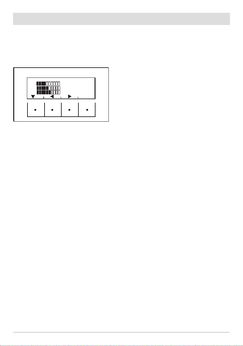
Supplying power
The power supply of the stove is indicated by “power level bars”: one bar corresponds to minimum power, 5 bars to maximum power;
this level is determined by the heating system heat requirements, the stove adjusts pellet loading parameters, fumes extraction, and
combustion air ow to comply with this requirement.
1
10:13 TIMER1 ECO
25°
23° AUTO
OFF
TEMP VENT
C
B
MENU
D
E
UPPER BAR: active requirements, active programmes, power bar, functions
CENTRAL BAR: room temperature, room set, room fan bar
LOWER BAR/KEYS: shut-o “B”, temperature set modify “C” and menu “E''
1 = power level bars
6
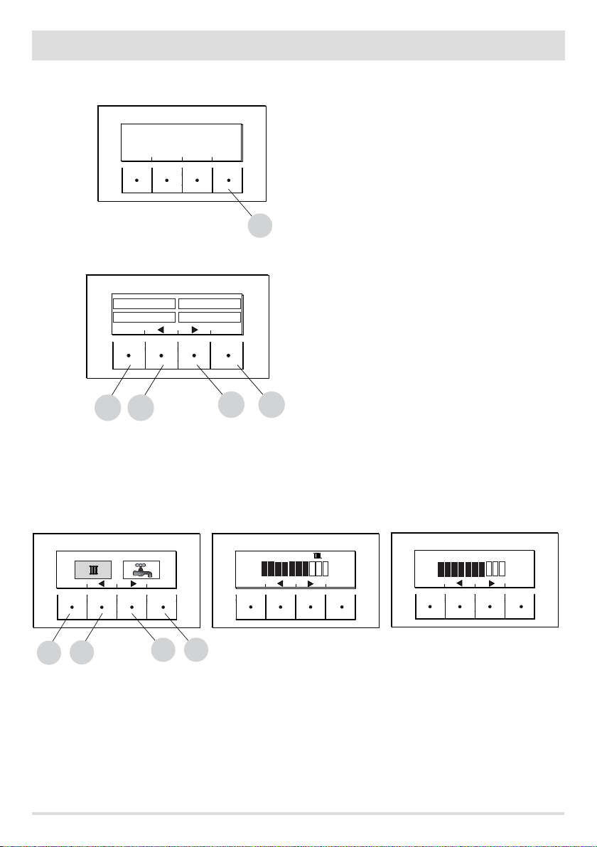
12 - MENU STRUCTURE
MENU STRUCTURE
To enter MENU press the "E" key (MENU).
OFF
ON
ECO
MENU
E
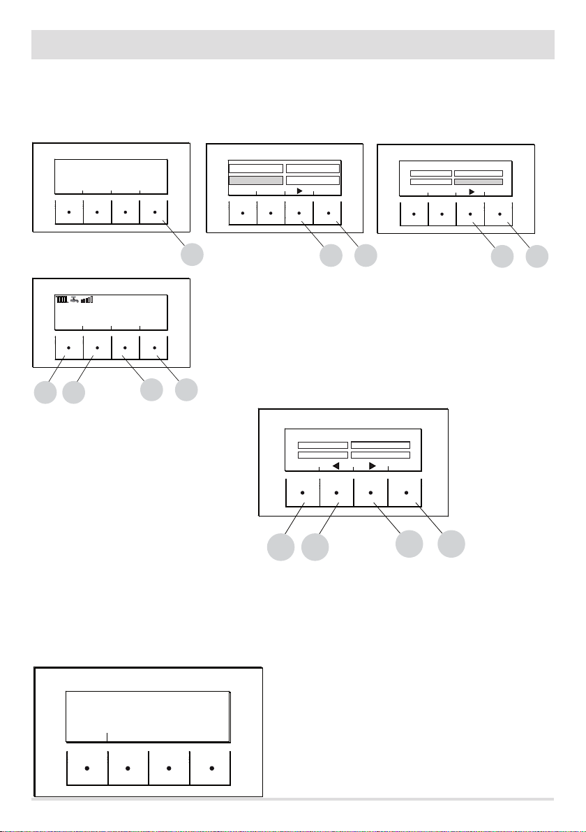
Next, this screen with the following functions is displayed:
TEMPERATURES
INFORMATION
EXIT
C
B
TEMPERATURE
When accessing this function, the main screen makes it possible to set heating and sanitary water temperature (if the boiler with probe
is congured - see menu settings input aux).
Select what is to be set and then using the C and D keys increase/decrease the temperature, use the E key to conrm while the B key is
used to exit and return to the main MENU.
PROGRAMS
SETTINGS
OK
Sub-menu
TEMPERATURE
PROGRAMMES
INFORMATION
SETTINGS
D
E
TEMPERATURE BUFFER
EXIT
EXIT
TEMPERATURES
71°
OK
TEMPERATURES
EXIT
C
B
OK
E
D
PROGRAMMES
In this case it is possible to choose the programme to be set.
Programme selection makes it possible to choose between one of the following options (one choice excludes the other):
TIMER 1
TIMER 2
MANUAL
TEMP. LEVELS
SLEEP FUNCT.
Technical Dept. - All rights reserved - Reproduction is prohibited
50°
OK
7
12 - MENU STRUCTURE
B
C
TEMPERATURES
INFORMATION
EXIT
PROGRAMS
SETTINGS
OK
D
E
PROGRAM SELECTION
TIMER 1 TIMER 2
TEMP.LEVELS FUNCT. SLEEP
ACTIVATE
EXIT ENTER
MANUAL
In the MENU screen, move the cursor with arrows "C"-"D" and select PROGRAMS, press ok "E" to conrm. Next select the programme you
wish to set.
Once completed, always press “ACTIVATE” to conrm the choice of programme.
The TIMER 1 and 2 programs are freely programmable for each 1/2 hour of the day on three dierent temperature indicators (T1-T2-T3)
and in dierent ways for each day of the week. The OFF level requires that the stove is switched o in that interval.
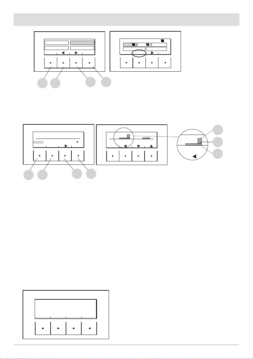
TIMER 1
0 246 12 18
MONDAY TUESDAY WEDNESDAY
COPY
EXIT
C
B
TIMER 1
0 246 12 18
MONDAY
OK
E
D
10:00 20°C
SAVE
6 12
10:00
T3
T2
T1
Example of temperature programming for Monday.
Select the TIMER 1 item from the PROGRAM menu and press the ENTER “E” key, using arrow “D” highlight Monday and press OK (“E”) to
enter programming.
Using the centre arrow keys “C” and “D” select the half hour interval to be selected and use the “E” key to set the temperature T1-T2-T3
(depending on whether the key is pressed 1-2-3 times, the corresponding temperature can be read in the bottom right of the display).
Once temperature programming for Monday is complete press the ''B'' SALVA (SAVE) key. If the same temperature scale of Monday is
desired for other weekdays, after saving ("E" key) press the "C" key (COPIA-COPY), select the day where the programme is to be copied
using the "D" key and press the "C" key (INCOLLA-PASTE). Repeat the same procedure until the programmes for all weekdays are complete.
At this point the stove is programmed according to your temperature needs, which can be modied at any time.
CAUTION:
In order to make stove use easier, MCZ supplies Timer 1 with preset weekly temperatures and times (according to the table below), while
Timer 2 is empty. In any case, it is possible to change times and temperatures of Timer 1 at any time.
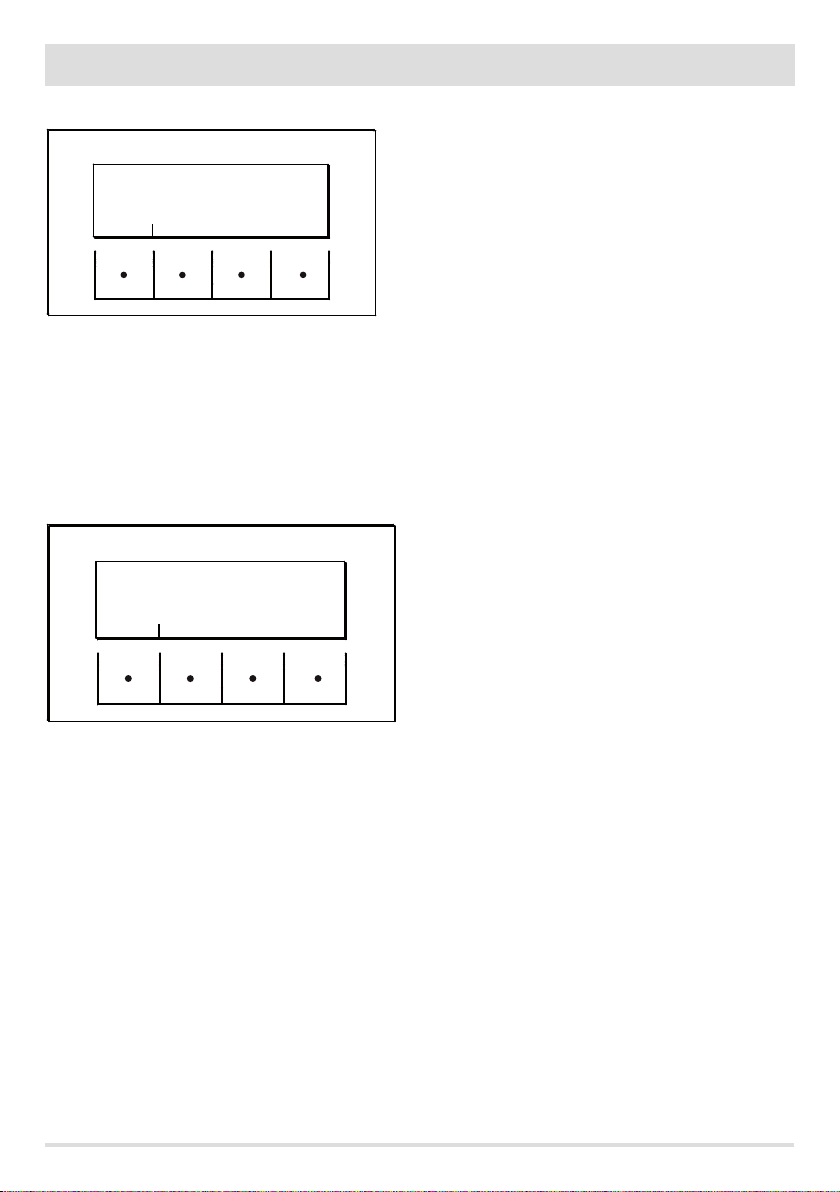
PANEL OFF DISPLAY FROM TIMER
When timer 1 (for example) has no set temperature, the panel highlights that the stove is in OFF position.
If the stove is o by MANUAL command, the timer will
OFF
03:33 TIMER 1
16° OFF
MENU
have no eect.
For the stove to come on with the timer, the panel must
display the image shown on the side; if this should not
be the case, it may be necessary to press the ON (“B”)
key.
8
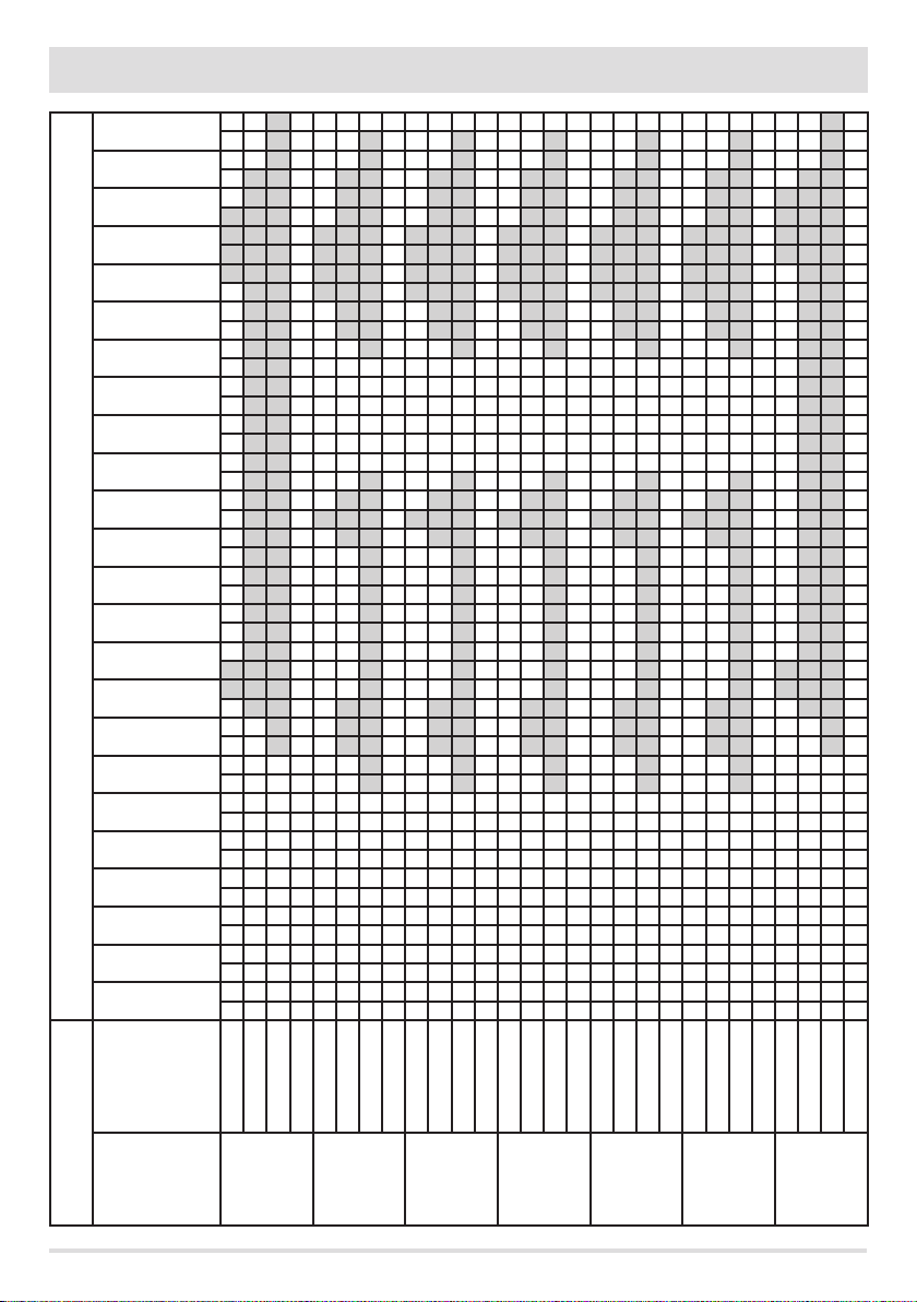
12 - MENU STRUCTURE
23:00
22:00
21:00
20:00
19:00
18:00
17:00
16:00
15:00
14:00
13:00
12:00
11:00
Time table
10:00
09:00
08:00
07:00
06:00
05:00
04:00
03:00
02:00
01:00
00:00
T3T2T1
OFF
T3T2T1
OFF
Temperatures*
Weekly programmes
Days
Sunday
Monday
* T1=16°C T2=20°C T3=22°C OFF=switched o
Technical Dept. - All rights reserved - Reproduction is prohibited
T3T2T1
Tuesday
OFF
T3T2T1
Wednesday
OFF
T3T2T1
Thursday
OFF
T3T2T1
Friday
OFF
T3T2T1
Saturday
OFF
9
12 - MENU STRUCTURE
MANUAL
This function can be activated from the menu PROGRAMME by pressing the key "C" ACTIVE. When this function is activated, the stove no
longer follows time programming of TIMER 1 or 2 programs, but it keeps the temperature set in the main screen throughout the 24-hour
time period. It is possible to switch to programmes at any time.
TEMPERATURE LEVELS
TEMP. LEVELS
T1
T2
T3
It is possible to change the 3 temperature levels referenced by timers in this menu.
From the PROGRAMS menu use arrow key "D" to move and select TEMP LEVELS, press the "E" key, and enter the temperature settings
screen. With the centre arrow keys "C" and "D", it is possible to increase/decrease the temperature value, while the "B" key is used to move
to the next temperature. With the "E" key (OK), the set values are conrmed.
SLEEP FUNCTION
The sleep function is only activated when the stove supplies power and makes it possible to programme a stove shut-o time. Shut o can
be delayed up to a maximum of 8 hours from current time and with a 10-minute resolution.
To activate, enter the PROGRAM menu, scroll using arrow key "D" up to Funct. SLEEP press the ATTIVA (ACTIVATE) "C" key. In the next
screen, using keys "C" and "D", increase or decrease the minutes (10 minutes each time the key is pressed) and press OK ("E" key) to
conrm the stove shut o time.
NOTE: If the stove is not supplying power the display shows the wording "NOT AVAILABLE".
16°
20°
22°
OK
10
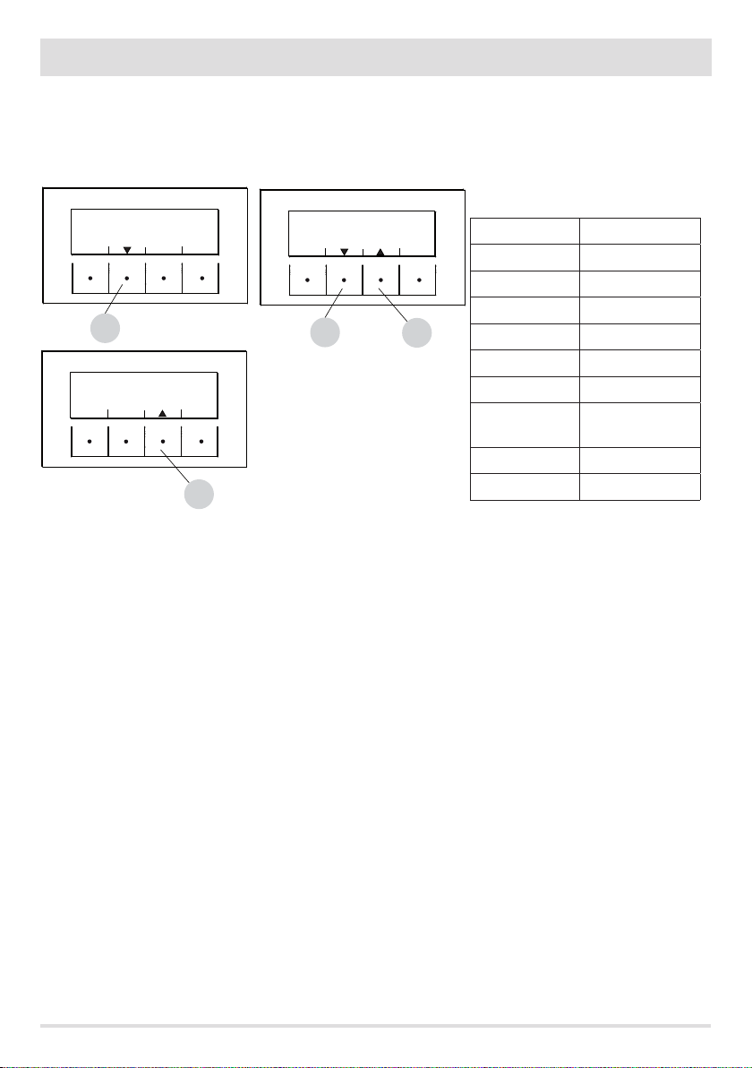
13 - MENU INFORMATION
INFORMATION
To enter the INFORMATION menu, proceed as follows:
from the main/initial screen, press the "E" Menu button, scroll using the "D" arrow key, up to the Information item, press the "E" ok key,
scroll again using the "D" arrow key up to software/data memory/all.memory/stove state and select the desired item, press OK using the
"E" key to enter the chosen information menu.
OFF
ON
MENU
TEMPERATURES
INFORMATIONS
EXIT
PROGRAMS
SETTINGS
E
10:13 TIMER1 ECO
25°
23° AUTO
OFF
TEMP AIR
C
B
MAIN SCREEN
The available information is:
• Software
MENU
D
E
SOFTWARE
ALARM HYSTORY
EXIT OK
• Data memory
• All. memory
• Stove state
B
SOFTWARE INFORMATION
The available data in this function are:
CODE
FIRMWARE
DATABASE
INTERFACE
It is information that can be used to identify the electronic part of the stove.
OK
D
INFORMATIONS
C
E
DATA HYSTORY
STOVE STATE
INFORMATIONS
SOFTWARE
ALARM HYSTORY
EXIT OK
D
DATA HYSTORY
STOVE STATE
E
D
E
INFORMATIONS-SOFTWARE
CODICE = MDUO
FIRMWARE = 140.7.08.08 [07]
DATABASE = 000.022
CONTROL PANEL = 14040613A/1000313B
EXIT
Technical Dept. - All rights reserved - Reproduction is prohibited
EXAMPLE
11
13 - MENU INFORMATION
DATA MEMORY-INFORMATION
INFORMATIONS-DATA HYSTORY
WORKING HOURS = 100
TOTAL IGNITIONS = 20
TEST DATE = 15/01/2013
EXIT
The available data in this function are:
WORKING HOURS
TOTAL IGNITIONS
TEST DATE
ALARM MEMORY-INFORMATION
It gives information about the last alarms detected.
INFORMATIONS-ALARM HYSTORY
ALARM 02 - 28/06/13 13:44 1
ALARM 02 - 21/06/13 08:03 2
ALARM 02 - 21/06/13 08.02 3
ALARM 02 - 21/06/13 09.46 4
EXIT
12
13 - MENU INFORMATION
STOVE STATE-INFORMATION
This menu is particularly useful if one wants to verify the stove work condition (State).
From the OFF screen, press the "E" Menu button, scroll with the "D" arrow key, up to the Information item, press the ok "E" key, scroll again
with the "D" arrow key up to stove state, press OK with the "E" key and one enters the stove State-information menu.
The items available within STOVE-STATE INFORMATION can be viewed using the "C" and "D" arrow keys and are:
INFORMATIONS-STOVE STATE
STATE = 0-OFF
WATER TEMP = -43°C SET = 70°C
ACTIVE+ = 471 SET = 400
SMOKE FAN = 0 SET = 0
EXIT
C
INFORMATIONS-STOVE STATE
MODBUS COM. = OFF IND.=4
EXIT
INFORMATIONS-STOVE STATE
FEED SCREW = 0 SET = 0
SMOKE TEMP = 30°C REQ = BOLL
AIR FAN = 0% POMP. = OFF
3 WAY VALVE = NO HY. CAND. =OFF
EXIT
C
D
• The main stove states that can be read on the display are:
STATE 1-9 various ignition phases
STATE 20-40 work state (power supply)
STATE 60-79 alarm state
STATE 80-84 shut o/cooling/autoeco state
STATE 85-93 auxiliary functions
STATE 94-95 cleaning state
state
water temp. set
aux sensor set
active+ set
D
fumes fan set
feed screw set
fumes temp. req
air vent. (not
pump
available)
relay aux spark plug
modbus com add.
• WATER TEMP.: Water temperature detected by the probe inside the stove and related SET
• AUX: PROBE: detects the value measured by the aux sensor (external/boiler/puer)
• ACTIVE+.: Value read by the Active Plus system and related SET
• FAN FUMES: Number of fumes fan revolutions and related SET
• FEED SCREW: number of feed screw revolutions and related SET
• FUMES TEMP.: temperature value read by the probe inside the stove
• REQ: (Heating/Sanitary) signals if system requires heat
• AIR FAN: Room fan operation level (not available)
• PUMP: signals if the stove's internal pump is turned on (ON) or turned o (OFF)
• AUX: RELAY: signals activation (ON) or the OFF state of Aux relay
• SPARK PLUG: Signals if spark plug is turned on or o
• MODBUS COM. External interface communication state
• ADD.: Address for communicating with modbus
Technical Dept. - All rights reserved - Reproduction is prohibited
13

14 - MENU SETTINGS
SETTINGS
To enter the menu SETTINGS, proceed as follows:
from the OFF screen, press the "E" Menu key, scroll with the "D" arrow key up to Settings item, press the ok "E" key, scroll again with the
"D" and/or "C" arrow key up to the chosen setting, press OK with the "E" key to enter the chosen menu.
It is possible to set the listed parameters from this screen. Each parameter has an info key to obtain brief information about the chosen
function.
OFF
ON
MENU
TEMPERATURES
INFORMATIONS
EXIT
E
PROGRAMS
SETTINGS
OK
D
• SETTINGS
• Auto Eco (default activated)
• Hydro Air (not available)
• Feed screw loading
• Pellet recipe
• Active +
• Cleaning cycle
• Language
• date - time
• Aux Input
• aux output
• Room Input
• T. on Pump
• Pump pwm
• Antifreeze function
• Plt sensor (not available)
• Modbus com.
• Display
• Technical menu (accessible by a specialised MCZ technician - password required)
• Active +
• Fume Analysis F
• Calib.Active
• Calib.S.fumes
• Diagnostics
• Parameters
• Boll advance
• Hour reset
SETTINGS
AUTOECO
FEED SCR LOAD
ACTIVE PLUS
EXIT
E
B
HYDRO-AIR
LOAD-RECIPE
CLEANING
OK
D
C
E
14
14 - MENU SETTINGS
AUTOECO (Factory activated)
SETTINGS-AUTOECO
DEACTIVATE
AUTOECO
INFO
C
B
The Auto eco mode turns the stove o when heating the system does not require heat, depending on the menu-settings-input aux
conguration.
AUTO ECO ACTIVE
The AutoEco active parameter (factory settings) is shown on the top right on the control panel display in the main screen. If heat is not
required, the stove turns o after the set time, switching to Auto Eco (State 84 - it is possible to see Auto eco in the Information Menu,
stove state).
NOTE: With the stove o, if T is set less than T room, or other heat request settings are fullled, the stove does not turn on.
ACTIVATE
AUTOECO
1
22° 18° AUTO
OFF
2
15:28 ECO
TEMP AIR
OK
D
E
MENU
IF YOU ACTIVATE THE AUTOECO, THE
STOVE GOES OFF WHEN THERE ARE
NO MORE HEAT REQUESTS
EXIT
B
1 = no heat request (T room > T set)
2 = T set
D
C
B
The stove turns on due to a request for heat when the set temperature is greater than the room temperature or there is a request for heat
from room thermostat 2 (see chapter on “aux input”).
AUTO ECO DEACTIVATED
With the stove on, if Auto eco is deactivated and there are no heat requests (dierent based on menu-settings-aux input settings) the
stove operates at minimum power.
The required condition for restarting is for there to be heat request for at least consecutive 10''; it is possible to restart if:
• at least 5 s have elapsed from when shutdown began
• the TH2O in the stove is < T set H2O
To modify the function:
from the Settings menu - using the arrow keys, select the AUTOECO function, press ok (E key) and press D or C key (arrow key) and select:
Activate = to modify the set time from 0 to 30 minutes (factory default 5 minutes)
Deactivate = to deactivate Auto Eco
Technical Dept. - All rights reserved - Reproduction is prohibited
E
15
14 - MENU SETTINGS
FEED SCREW LOADING (only with the stove o )
DEACTIVATE
INFO
B
SETTINGS-FEED SCR LOAD
LOAD
C
ACTIVATE
LOAD
OK
D
E
USE THE 'FEED SCREW LOADER' WHEN
THE FEED SCREW IS EMPTY AND
YOU MUST LOAD IT QUICKLY
EXIT
B
This function is for lling the pellet loading system. It can only be activated with the stove o.
To enter the function:
from the Settings menu - press OK (E key), press the D key (arrow key) and scroll up to load feed screw, press OK (E key) and activate the
function, press ok (''E'' key) to conrm. To interrupt the function, go back to the load feed screw menu, press OK (“E” key), arrow key “C”,
disable load and press OK (“E” key).
PELLET RECIPE (PLT RECIPE)
INFO
B
SETTINGS-LOAD-RECIPE
+15%
C
OK
D
E
CHANGE BY PERCENT THE FEED SCREW
SPEED TO ADAPT THE STOVE TO THE TYPE
OF PELLET
EXIT
B
This function is for adapting the stove to the type of pellet in use. As there are many types of pellet available on the market, stove
operation can vary considerably according to the quality of the fuel. When the pellets clog up the brazier due to excess loading of fuel,
vice-versa if the ame has a tendency to shut-o, it is possible to decrease/increase the amount of pellets in the brazier:
The available values compared to factory settings are:
+15% +10% + 5%; 0%; -10% -20% -30%
To modify the pellet recipe, in sequence, press:
from the Settings menu - press ok (E key), press the D key (arrow) scroll up to plt recipe and press OK (E key) and enter the function, using
the “C” and “D” keys to modify the parameter and press OK (“E” key).
ACTIVE +
The pellet type is not a problem because the stoves are equipped with the Active system and automatically adapt to pellet of any length
with a diameter of 6-8 mm. Eective and ecient combustion is independent from any type of connection to the ue which, with
traditional systems, may constitute a problem during the installation phase.
Thanks to an internal sensor, the stove is extremely reliable and precise, combustion air is constantly adjusted based on the quantity of
pellets present in the brazier, thus guaranteeing an eective and ecient combustion that is translated into decreased consumption,
emissions, and less frequent cleaning.
Thanks to Active plus, it is possible to control and communicate with the stove, even by way of Smartphone and tablet. Since it is possible
to manage more evolved gear motors (with continuous operation), the new pellet stoves equipped with active plus are more silent.
This function is used to adjust combustion air if the ame is too high or too low.
It can be activated from the SETTINGS menu, scroll using the “D” arrow key up to the “ACTIVE +” function, press OK using the “E” key, and,
16

14 - MENU SETTINGS
SETTINGS-SMOKE FAN
0%
INFO
B
using the “D” arrow key modify the parameter and press “ok” “E” key.
The xed parameters that can be set are: +10; +5; -5; -10
OK
D
E
CORRECT THE LEVEL OF
COMBURENT AIR
EXIT
B
CLEANING
This function can only be activated while the power supply is in the following mode:
SETTINGS-CLEANING
DEACTIVATE
CLEANING
INFO
C
B
from the Settings menu- press ok (E key), press the D key (arrow key), scroll up to the “ciclo pulizia” (cleaning cycle) press OK (E key)Activate/deactivate cleaning.
This procedure activates the fumes extraction fan at the maximum level in order to clean the brazier and expel soot.
ACTIVATE
CLEANING
OK
E
IMMEDIATELY ACTIVATE A CLEANING
CYCLE OF THE BRAZIER
EXIT
B
LANGUAGE
This function is used to choose the desired language among those set in the control panel.
To enter the function, from the Settings menu - press OK (E key), press the D key (arrow key) and scroll up to language item, press OK (E
key) and choose the language among the various ones set and nally press OK (“E” key) to conrm.
The available languages are: Italian/English/French/German/Spanish/Dutch/Danish
SETTINGS-LANGUAGE
ITALIANO
ENGLISH
FRANCAIS
C
B
Technical Dept. - All rights reserved - Reproduction is prohibited
OK
D
E
17

14 - MENU SETTINGS
TIME-DATE
This function is used to set date and time.
To enter the function, from the Settings menu - press ok (E key), press the D key (arrow key) and scroll up to the date-time item, press OK
(E key) to enter the function. Next, press the "E" (ok) key again to modify day/month/year/hour and minutes. To modify the parameters,
use the “C” and “D” (arrow keys) keys and press the "E" key to conrm.
SETTINGS-TIME-DATE
TODAY IS MONDAY
AND IT IS
EXIT
C
B
AUX INPUT (using one of the following parameters excludes the other)
The auxiliary input allows you to choose the system conguration type based on which the stove is connected.
To enter the function press:
from the Settings menu- press ok (E key), press the D (arrow) key and scroll up to the Aux Input item and press OK (E key). Using the “C”
and “D” keys select the desired heating system type and press ok with the “E” key.
It is possible to connect the following to the auxiliary input:
SETTINGS-INPUT AUX
THERM.AMB.2
W.CYLIN.PROB.
BUFFER PROBE
INFO
EXT.SENSOR
W.CYLIN.THERM.
BUFFER THERM.
24/06/13
14:14
OK
OK
D
E
D
C
B
E
Room thermostat 2
External probe
Boiler probe
Boiler thermostat
Puer probe
Puer Thermostat
Note: The boiler probe/thermostat choice implies the three-way aux output designation (contacts 7-8-9 on the rear terminal board).
The puer probe/thermostat choice implies the pump aux output designation (contacts 7-8-9 on the rear terminal board).
• Room Therm.2
The stove heat request may take place from any part of the room probe or from the “Termostato Amb 2” (Room thermostat 2) installed in
a room that is dierent from the one where the stove is positioned and is connected to terminals 1 and 2 of the back terminal board. The
stove's request for heat may be due to the closure of the contacts on the terminals and, simultaneously, to the stove's ambient probe (it is
not a case of either or). If you only want the external thermostat, please see “Ambient inlet”.
Notes: Installation of this thermostat is optional, the stove can also operate without it. Since the contact is N.O., the room probe is the only
heat request command.
Possible active weekly programming does not act on Room Thermostat 2 but rather on the probe on board the stove.
18

14 - MENU SETTINGS
• External probe
It makes it possible to work with system temperature adjustment. If installing an external probe on terminals 1 and 2 (NTC 10KOhm at
25°C b=3435) water temperature is automatically calculated by the electronics based on external temperature according to the curves
shown below:
The external probe must be installed on an external wall exposed towards North or North-West. If necessary, it is possible to correct the
value read by the probe by + 5 -5°C.
• Boiler probe
To activate this option, connect a probe (NTC 10KOhm at 25°C b=3435) to points 1 and 2 of the back 9-pole terminal board.
The heat request occurs when the boiler probe reads a temperature that is 2°C below the one set by the accumulation temperature marked
by a tap in the temperature menu.
In this conguration, the aux output is congured as a potential free contact to control the 3-way valve (contact 7-8-9 of the back 9-pole
terminal board)
• Boiler thermostat
To activate this option, connect a Normally Open (N.O.) contact thermostat to points 1 and 2 of the back 9-pole terminal board.
The heat request occurs when the boiler thermostat closes the contact.
Even with this conguration, the Aux output is congured as a potential free contact to control the 3-way valve (contact 7-8-9 of the back
9-pole terminal board).
• Puer probe
To activate this option, connect a probe (NTC 10KOhm at 25°C b=3435) to points 1 and 2 of the back 9-pole terminal board.
The heat request occurs when the boiler probe reads a temperature that is 2°C below the one set by the accumulation temperature marked
by a radiator in the temperature menu.
During installation with the puer, stove operation is only and exclusively determined by the puer probe and not by the room probe. The
purpose of the room probe on the stove is only to control the heating system pump controlled by the potential free contact N.O.: (max 5
ampere, not suitable for brushless pumps with upper start-up current) on terminals 8-9.
Technical Dept. - All rights reserved - Reproduction is prohibited
19

14 - MENU SETTINGS
• Puer thermostat
To activate this option, connect a Normally Open (N.O.) contact thermostat to points 1 and 2 of the back 9-pole terminal board.
Even with this conguration the purpose of the room probe on the stove is only to control the heating system pump controlled by the
potential free contact on terminals 7-8-9.
INPUT AUX
1 2 3
POS.1-2 EXTERNAL THERMOSTAT/THERMOSTAT/BOILER/PUFFER
(AUX INPUT) BOILER PROBE/PUFFER
POS.3-4 ROOM PROBE (ROOM INPUT) POS.7-8-9 AUX OUTPUT RELAY
The terminal block is at the back of the stove. Remove the two screws and protective cover to access it
4
5
6
POS.5-6 HOME AUTOMATION
NC
7
NO
8 9
C
20

14 - MENU SETTINGS
HYDRO AIR STOVE PRINCIPLE DIAGRAMS
The following diagrams are to be used only as a guideline. For proper connection, always follow the notes of the
plumbing and heating installer. The plumbing system must meet local, regional, or national requirements in
force. Installation and verication of operation is to be performed only by specialised, authorised personnel. The
manufacturer will not be held liable for non-compliance with the provisions listed above.
HEATING ONLY CONFIGURATION
CONFIGURATION WITH HEATING AND DOMESTIC HOT WATER
Technical Dept. - All rights reserved - Reproduction is prohibited
21

14 - MENU SETTINGS
BOILER CONFIGURATION
NO
NC
POS.1-2 = BOILER
1 2 345
PROBE/THERMOSTAT
HYDRO STOVE WITH PUFFER CONFIGURATION
6
7
8 9
C
POS.1-2 = PUFFER PROBE/
THERMOSTAT
22
1 2 345
C
NO
NC
6
7
8 9

14 - MENU SETTINGS
ONLY FOR UK
TOBA HYDRO
Technical Dept. - All rights reserved - Reproduction is prohibited
1 2 345
C
NO
NC
6
7
8 9
23

14 - MENU SETTINGS
ONLY FOR UK
TOBA HYDRO
C
NO
NC
6
7
1 2 345
8 9
24

14 - MENU SETTINGS
ONLY FOR UK
TOBA HYDRO
Technical Dept. - All rights reserved - Reproduction is prohibited
1 2 345
C
NO
NC
6
7
8 9
25

14 - MENU SETTINGS
ONLY FOR UK
TOBA HYDRO
C
NO
NC
6
7
1 2 345
8 9
26

14 - MENU SETTINGS
OUTPUT AUX
B
ALARM
REMOTE
INFO
SETTINGS-OUTPUT AUX
BOILER
AUX
C
EXIT
TEMP.
OK
D
E
SET AMBIENT INPUT AS A PROBE OR
THERMOSTAT.
(TERMINALS 3 - 4)
EXIT
B
The AUX output makes it possible to use a relay contact, based on the system conguration type chosen in the Aux Input menu.
It acts on contact 7-8-9 of the external terminal board.
The functions can only be selected if the boiler or puer conguration has not been chosen in the Aux Input menu, and
are:
• Remote alarm (9-8=C-NO)
• Auxiliary boiler (9-7=C-NC) (SEE DIAGRAMS ON THE NEXT PAGE)
• Auxiliary output in temperature (9-8-7=C-NO-NC)
To enter the function press:
from the Settings menu- press ok (E key), press the D (arrow) key and scroll up to the Aux Output item and press OK (E key). Using the “C”
and “D” keys to select the Remote Alarm/Aux boiler/Output in temp and press OK ("E" key).
• If the Aux output is set on Remote Alarm, the NO contact is closed when an alarm is present.
• If the Aux output is set to Auxiliary Boiler, the NC contact remains closed in all alarm states, in = "OFF" state, in 80 “Shutdown” state,
and in 51 “COOL” state. Under all conditions it remains open.
• Output temperature: the NO contact closes when the Boiler temperature exceeds the value set by the user. It can be set from 30 to 60,
it is used, for example, to disconnect the aux boiler above a certain temperature (using the NC contact) or to start an external pump
at temperature (using the NO contact)
• If the boiler conguration has been chosen, the Aux contact is set on “Three-way boiler valve”: the contact changes when there is a
heat request from the boiler.
• If the Puer conguration has been chosen, the Aux contact is set on “Pump control”: the NO contact closes when there is a heat
request from the Room PROBE
Technical Dept. - All rights reserved - Reproduction is prohibited
27

14 - MENU SETTINGS
EXAMPLE 1 - CONNECTION TO THE ROOM THERMOSTAT INLET OF THE AUX BOILER
Ingresso
termostato
7
1 2 345
6
NC
NO
EXAMPLE 2 - ROOM THERMOSTAT WITH DOUBLE CONTACT
• ROOM THERMOSTAT 2 TERMINALS 1-2
• ROOM PROBE TERMINALS 3-4
• AUX BOILER TERMINALS 7-9
8 9
C
N L
ambiente
CALDAIA AUX
7
8 9
1 2 345
6
C
NC
NO
EXAMPLE 3 - ROOM THERMOSTAT WITH DOUBLE CONTACT
• ROOM INLET TERMINALS 3-4 SET ON ROOM THERMOSTAT (SEE RELATIVE PARAGRAPH)
• AUX BOILER TERMINALS 7-9
N L
7
8 9
1 2 345
6
C
NC
NO
28
Ingresso
termostato
ambiente
CALDAIA AUX
Ingresso
termostato
ambiente
CALDAIA AUX

14 - MENU SETTINGS
INPUT AMB
The room input is used to set the probe or the thermostat at terminals 3-4 of the back terminal board of the stove.
The stove has the room probe set as default factory settings.
By selecting the thermostat, it is possible to replace the probe on the stove with a thermostat that requests heat when the contact is
closed.
B
SETTING-INPUT AMB
PROBE
AMB.
INFO
C
THERMOSTAT
AMB.
OK
D
E
SET AMBIENT INPUT AS A PROBE OR
THERMOSTAT.
(TERMINALS 3 - 4)
EXIT
B
To enter the function press:
from the Settings menu - press ok (E key), press the D key (arrow) and scroll up to Room Input, press OK (E key) and select room thermostat,
press E key to conrm.
Attention!!! If room temperature is selected, weekly hourly Programming will no longer be available.
PUMP ON T
This function enables adjustment of the pump activation temperature.
To enter the function press:
from the Settings menu- press ok (E key), press the C-D key (arrow) and scroll up to temp.On pump, press OK (E key)- Modify the
temperature using the central C and D keys, press the E key to conrm.
INFO
SETTINGS-T.ON PUMP
60°
OK
MINIMUM TEMPERATURE OF THE
WATER TO START THE PUMP
OF THE BOILER
EXIT
D
C
B
E
Technical Dept. - All rights reserved - Reproduction is prohibited
B
29

14 - MENU SETTINGS
PWM PUMP
This function is used to set high eciency pump speed.
To enter the function press:
from the Settings menu- press ok (E key), press the C-D key (arrow) and scroll up to PWM Pump, press OK (E key)- Modify the percentage
using the central C and D keys, press the E key to conrm.
INFO
B
SETTINGS-PUMP PWM
AUTO
C
OK
D
E
SET THE SPEED OF THE
MODULATING HIGH EFFICIENCY
PUMP
EXIT
B
FUNCT. ANTI-FREEZE
It consists in activating the pump (level 1) or the stove (level 2) and is automatically activated by the temperature read by the stove probe
and the temperature read by the external probe (if present and connected to the aux input).
The level 1 anti-freeze activation conditions (PUMP ON) are:
boiler temp < anti-freeze set +3°C
The level 2 anti-freeze activation conditions (PUMP and FLAME ON) are:
boiler temp = anti-freeze set
Anti-freeze activation conditions on external probe (if present) are:
ext_ltered temp < anti-freeze set -3°C
SETTINGS-ANTI FROZEN
DEACTIVATE
ANTI FROZEN
INFO
ACTIVATE
ANTI FROZEN
OK
SET THE ACTIVATION
TEMPERATURE OF THE
ANTIFREEZE FUNCTION
EXIT
D
C
B
E
B
To enter the function, press and adjust anti-freeze set:
from the Settings menu- press ok (E key), press the C-D key (arrow) and scroll up to Antifreeze function and press OK (E key)- Activate and
set (from 1 to 5°C) or Deactivate the function and press the E key to conrm.
PELLET SENSOR
Optional Function.
30

14 - MENU SETTINGS
MODBUS COM.
It is a communication system that makes it possible for the stove to receive commands from a Smartphone/tablet through a Web/Wi-Fi
interface.
To enter the function press:
from the Settings menu - press ok (E key), press the C-D key (arrow) and scroll up to Modbus com. and press OK (E key)- Set the address
and press E key to conrm.
SETTINGS-MODBUS COM.
ADDRESS
INFO
C
B
3
OK
D
E
SET THE ADDRESS MODBUS SLAVE
BAUD RATE 19.200 1 STOP BIT -
EVEN PARITY - 19200 8N1
EXIT
B
DISPLAY
Adjust display contrast and brightness. This function is found in:
from the Settings menu- press ok (E key), press the C-D key (arrow) and scroll up to Display, press OK (E key)- Modify the settings using the
B - C - D keys and press the E key to conrm.
SETTINGS-DISPLAY
CONTRAST
BRIGHTNESS
B
C
OK
D
E
Technical Dept. - All rights reserved - Reproduction is prohibited
31

15 - TECHNICAL MENU
TECHNICAL MENU
To access the technical menu you must contact the assistance centre as it requires a password.
To make changes in the technical menu, enter the SETTINGS menu, press the "E" (OK) key, scroll using the “C”-”D” arrows keys and select
Technical menu and press OK (E key)- Enter the password and press the E key to conrm.
SETTINGS-TECH. MENU
INSERT PASSWORD
0000
EXIT
OK
C
B
To enter the password:
using the C and D keys, set the numbers (1-2-3....9) with the E (OK) key conrm and move on to the next digit, once the four digits have
been entered, press the E key to enter the technical menu.
The technical menu displays the following parameters:
• ACTIVE +
• FUMES ANALYSIS F.
• CALIB.ACTIVE
• CALIB.S.FUMES
• DIAGNOSTIC
• PARAMETERS
• BOLL ADVANCE
• RESET HOURS
D
E
32

16 - SAFETY DEVICES AND ALARMS
SAFETY DEVICES
The product is tted with the following safety devices
ACTIVE +
Besides adjusting the stove operation, it also guarantees that the pellet loading feed screw is blocked if unloading is blocked or there is
signicant back pressure.
SMOKE TEMPERATURE PROBE
Detects the temperature of the smoke, thereby enabling start-up or stopping the product when the temperature drops
below the preset value.
CONTACT THERMOSTAT IN THE FUEL TANK
If the temperature exceeds the preset safety level, it immediately shuts down the running of the stove.
WATER THERMOSTAT
If the temperature exceeds the preset safety level, it immediately shuts down the running of the stove.
WATER TEMPERATURE SENSOR
When the water reaches the stop temperature (85°C), the probe automatically instructs the boiler to carry out
automatic "OFF Stand-by" shut-o.
ELECTRICAL SAFETY
The stove is protected against violent changes in current by a general fuse located in the control panel at the back of the
stove. Other fuses that protect the electronic boards are found on the latter.
SMOKE FAN
If the fan stops, the electronic board shuts o the supply of pellets in good time, and an alarm message is displayed.
GEAR MOTOR
If the reduction motor stops, the stove will continue to run until the ame goes out due to lack of fuel and until
a minimum level of cooling is reached.
TEMPORARY POWER CUT
When a power cut is less than 10", the stove returns to its previous operating state; if it is more, it executes a
cooling/re-ignition cycle.
FAILED START-UP
If during ignition no ame develops, the stove will go into alarm condition.
ANTI-FREEZE FUNCTION
If the probe in the boiler detects a water temperature of less than 5°C, the circulation pump is automatically activated to keep the system
from freezing.
PUMP ANTI-SEIZURE FUNCTION
If the pump is not used for prolonged periods, it is activated periodically for a few seconds to keep it from
seizing up.
Technical Dept. - All rights reserved - Reproduction is prohibited
33

16 - SAFETY DEVICES AND ALARMS
TAMPERING WITH THE SAFETY DEVICES IS PROHIBITED
If the product is NOT used as described in this instruction manual, the manufacturer declines all liability for any
damage caused to persons and property. In particular:
• All the necessary measures and/or precautions must be adopted when performing maintenance, cleaning and
repairs.
• Do not tamper with the safety devices.
• Do not remove the safety devices.
• Connect the product to an ecient smoke expulsion system.
• First, check that the environment where it is to be installed is properly ventilated.
Only after eliminating the cause of the intervention of the safety system is it possible to start the product back up.
This manual will help you understand which anomaly has occurred, and explain how to intervene according to the
alarm message displayed on the appliance.
Mechanical stove block
The following conditions may cause the mechanical stove block:
• Overheating of the structure and pellet tank
• Overheating of the water in the boiler
• High pressure of the outlet fumes (read on the pressure switch) and possible obstruction of the outlet.
The control panel will indicate the cause of the alarm and sound an acoustic warning.
In this situation, the automatic shut-down sequence is activated.
When this sequence is initiated, any attempt to restart the system will be ineective.
34

16 - SAFETY DEVICES AND ALARMS
ALARM ALERTS
If there is an operational anomaly, the stove enters the alarm phase displaying the problem that has taken place through a code, a brief
description of the alarm type and an acoustic warning.
The following table describes the possible alarms indicated by the stove, associated to the respective code that appears on the panel and
helpful tips to solve the problem.
B = RESET (cancels alarm)
C = INFO (provides information on the alarm type)
E = MENU
WRITTEN ON THE
DISPLAY
A01
NO IGNITION
A02
NO FLAME
A03
PLT SAFETY
TYPE OF PROBLEM SOLUTION
The re does not ignite.
(without acoustic alarm)
The re goes out abnormally.
(without acoustic alarm)
Pellet tank temperature is too high
A05
OBSTRUCTION
RESET
C
B
Check the level of pellets in the tank.
Check that the brazier rests correctly in its seat and has no
visible deposits or unburnt pellets.
Check whether the ignition plug becomes hot.
Empty and clean the brazier before relighting.
Check the level of pellets in the tank.
Check that the brazier rests correctly in its seat and has no
visible deposits of unburned pellets.
Wait for the cooling phase to end, cancel the alarm and
reduce pellet loading (SETTINGS MENU - Pellet recipe). If the
alarm persists, contact the service centre.
MENUINFO
E
A04
FUMES TEMP
A05
OBSTRUCTION
Technical Dept. - All rights reserved - Reproduction is prohibited
Fumes temperature is too high
Chimney ue clogged
Wait for the cooling phase to end, cancel the alarm and
reduce pellet loading (SETTINGS MENU - Pellet recipe). If the
alarm persists, contact the service centre.
Verify brazier clogging, smoke duct, lower compartment and
door closing. If the alarm persists, contact the service centre.
35

16 - SAFETY DEVICES AND ALARMS
WRITTEN ON THE
DISPLAY
A08
FLUE GAS FAN
A09
SMOKE TEMPERA
TURE PROBE
A11
GEAR REDUCER
A13
BOARD TEMP
A14
ACTIVE SENSOR
A18
WATER SIC
TYPE OF PROBLEM SOLUTION
Check that the lower compartment is clean (see the
Faulty smoke fan.
Smoke sensor fault.
Feed screw gear reducer fault.
Electronic board overheating
Active sensor anomaly
Water thermostat intervention
pages dedicated to stove cleaning) and verify that it is not
obstructed; clean it and cancel the alarm.
If the alarm persists, contact the service centre.
Contact an authorised service centre to have the component
checked and, if needed, replace the component.
The component is not working regularly.
Contact an authorised service centre to have the component
checked and, if needed, replace the component.
Wait for the cooling phase to end, cancel the alarm and
reduce pellet loading (SETTINGS MENU - Pellet recipe). If the
alarm persists, contact the service centre. .
Active Plus sensor operation anomaly. Contact an authorised
service centre to have the component checked and, if needed,
replace the component.
Water temperature is too high or thermostat operation
anomaly. If the alarm persists, contact the service centre.
A19
WATER PROBE
A20
AUX PROBE
Exiting the alarm conditions
NEVER open the appliance door whilst the stove is either in the initial startup or on its shut down cycle, pellets will
still be smoldering or therefore volatiles may be present.
ATTENTION!
If during operation or initial ignition you encounter smoke spillage in to the room from the appliance or the ue
then please switch o the appliance, ventilate the room and contact the installation / service engineer immediately.
36
Fault with water sensor.
Auxiliary probe fault
Possible fault in the safety component. Contact an authorised
service centre to have the component checked and, if needed,
replace the component.
Possible component fault.
Check that the probe inserted in the system respects the
characteristics specied in the instructions (see external
probe).
Contact an authorised service centre to have the component
checked and, if needed, replace the component.

16 - SAFETY DEVICES AND ALARMS
When the stove enters an alarm state, an automatic cooling/shut-o phase begins, at the end of which the cause of the alarm is displayed
on the small panel.
Before resetting the alarm, follow the controls indicated in the previous table, and them press the RESET key for a few seconds (or remove
power to the stove using the main ON/OFF switch on the back of the stove).
If the indicated actions do not solve the problem, the alarm condition will occur once again with dierent timing based on the alarm type:
in this case, contact technical assistance.
SHUT DOWN
If the shut-down key is pressed or one of the following conditions occurs:
• power request ends (Power = 0) for Ecostop, Timer, Sleep
• an alarm condition occurs
• water overheating occurs
the stove enters the shut down and thermal cooling phase that automatically includes the execution of the following phases:
• pellet loading stops
• the room fan maintains the set speed until it cools down
• the fumes extractor is activated at maximum speed and remains on for a xed period of 5 minutes, at the end of which the stove o
temperature is reached.
During the shut down phase, the small panel displays the wording OFF (see screen) but if it is in shut down due to an alarm condition, the
small panel displays the related code (See alarms table)
OFF
ON
ECO
MENU
EB
BLACKOUT WITH STOVE ON
If power is lost for less than 10" from stove start-up, it is repositioned in the phase where it was before the power failure.
If the loss of power exceeds 10", when the stove is powered once again, it goes back to the previous operational condition with the
following procedure it
• carries out a cooling phase, during which the panel displays OFF BLACKOUT
• restarts the stove
If the stove is in ignition phase when the blackout occurs, it will not turn back on once the power is restored (there is a risk that residual
pellet is present in the brazier) and the panel will display OFF BLACK-OUT.
If the ON key is pressed during the cooling phase, the stove stops executing the blackout restore state and it proceeds with ignition as
requested by the command. In the same way, pressing OFF is interpreted as a shut o command.
Technical Dept. - All rights reserved - Reproduction is prohibited
37

17 - RECOMMENDATIONS FOR A SAFE USE
RECOMMENDATIONS FOR A SAFE USE
ONLY A SUITABLE INSTALLATION ACCORDING TO THE UK BUILDING REGULATIONS (ADJ) AND A PROPER MAINTAINANCE
AND CLEANING OF THE PRODUCT CAN ASSURE YOU THE CORRECT FUNCTIONALITY AND A SAFE USE OF YOUR STOVE (ONLY
FOR UK).
We wish to notify you that we have been made aware of incidents involving domestic heating pellet stoves resulting from the stoves
having been incorrectly installed or inadequately maintained. In some cases the incident provoked an explosion that caused the glass
door on the stoves to shatter.
We would like to assure you that all of our products are very safe and are certied to the required European standards. The ignition
system has been tested carefully to increase the lighting eciency and avoid any trouble even in the worst working condition. Moreover
our structures are also provided with a safety device studied to discharge the eventual overpressure in combustion chamber, and avoid
any damage to the product and consequent risk for the nal user. However, like any stove, our stoves need to be properly installed and
maintained if they are to work safely.
Our studies suggest that these explosions are mainly caused by a combination of some or all of the following factors:
• Clogged brazier holes or a deformed brazier, resulting from insucient maintenance, creating the conditions for a delayed ignition
causing a build up of unburnt gases
• Insucient combustion air due to the stove not having a big enough air inlet or not having an air inlet at all
• The use of smoke connections or ue pipe assembly which don’t comply with UK regulations and which don’t create the draught
required to eectively suck the smoke outside (e.g. too many bends in the ue).
• Partially blocked ue pipes, which indicates poor maintenance, reducing the draw on the chimney making ignition dicult.
• The chimney terminal not complying with our installation instructions and failing to prevent potentially dangerous down-draught.
This component becomes essential when the stove is installed in windy areas like coastal zones.
Any of the above factors or any combination of them could generate unburnt gasses which in the worst cases could explosively ignite
when there becomes enough oxygen present.
To avoid this rare but not impossible inconvenient, rst of all the installation shall be done in compliance with UK building regulations and
the suggestions described in this manual.
Furthermore it’s absolutely important to respect the following simple rules:
• The brazier shall be always layed down in its proper position before any use of the product, removing completely the dirt if present
in the base plate
• Pellets must not be fed manually into the brazier, both before ignition and during the working condition.
• Eventual accumulated unburnt pellets in the burner after a failed ignitions must be removed before lighting
• If a failed ignition aects the product repeatedly, despite a clean brazier and a usual fuel loading, we recommend that you
immediately stop using the stove and contact a qualied technician to check the stove functionality.
The respect of these suggestions is absolutely enough to guarantee a safe ignition and to avoid any inconvenient to the product.
If the above precautions are not fullled, and the ignition shows an abnormal amount of pellet in the brazier and a consequent heavy
generation of unburned gas in the combustion chamber, respect carefully the following suggestions:
• Do not switch o the electrical power from the stove for any reason: this would arrest the gas exhaust blower with a consequent
spread of smoke into the room.
• Precautionally open the windows to ventilate the installation room from eventual smoke outlet in ambient (the ue gas outlet could
work not properly).
• Do not open the re door: this would aect the regular smoke evacuation from the chimney.
• Simply switch o the stove by pressing the on/o button in the control panel (not the rear button of power supply!), and wait till the
smoke has been evacuated completely.
• Before any re-lighting attempt, clean completely the brazier and its air passages from any dirt and unburned pellet; put it in the
proper position removing the dirt eventually present in the base plate. If a repeated failed ignition happens, stop using the stove and
contact a qualied technician to check the stove and chimney functionality
38

18 - MAINTENANCE AND CLEANING
Example of a clean brazier
Only a proper maintainance and cleaning of the product can assure you the correct functionality and a safe use of your stove (read chapter
12).
ATTENTION!
All the cleaning operations of all parts must be performed with the product completely cold and the plug
disconnected.
Disconnect the product from the 230V power supply before performing any maintenance operation.
The product requires little maintenance if used with certied high quality pellets.
Example of a dirty brazier
DAILY OR WEEKLY CLEANING PERFORMED BY THE USER
Brazier cleaning
Before ignition, always clean the “T” brazier and remove any ash or incrustation from it that might obstruct the air ow holes, paying
attention to hot ash. In the case of ignition failure, or if fuel in the tank runs out, unburned pellets may accumulate in the brazier. Always
empty the residue in the brazier before each start-up. Only if ash is completely cold may a vacuum cleaner be used to remove it. In this
case, use a suitable vacuum cleaner to remove small sized particles.
REMEMBER THAT ONLY A CORRECTLY POSITIONED AND CLEAN BRAZIER CAN GUARANTEE THE IGNITION AND OPTIMAL
OPERATION OF YOUR PELLET PRODUCT. IN CASE OF FAILED IGNITION AND AFTER ANY OTHER LOCK STATE OF THE
PRODUCT, IT IS ESSENTIAL TO EMPTY THE BRAZIER BEFORE PROCEEDING TO RESTART.
For the brazier to be cleaned properly, remove it from its housing completely and thoroughly clean all the holes and the grate on the
bottom. If good quality pellets are used, you will normally only need to use a brush to restore the optimal operating conditions of the
component.
Ash tray cleaning
Remove and empty the “U” ash tray. Wipe away any residual ash before reinserting the tray. Your experience and the quality of the pellets
will determine the ash tray cleaning frequency. However, it is recommended not to exceed 2 or 3 days.
CLEANING THE GLASS
It is recommended to clean the ceramic glass with a dry brush, or if it is very dirty, spray a little specic detergent and clean with a cloth.
ATTENTION!
Do not use abrasive products and do not spray the glass cleaning product on the painted parts and on the door
gaskets (ceramic bre cord).
Technical Dept. - All rights reserved - Reproduction is prohibited
39

18 - MAINTENANCE AND CLEANING
CLEAN THE EXCHANGER AND THE COMPARTMENT BENEATH THE BRAZIER EVERY 2/3 DAYS
Cleaning the exchanger and the compartment beneath the brazier is a simple operation but very important if the boiler is to maintain
optimal performance.
We therefore recommend cleaning the internal exchanger every 2-3 days, performing these simple operations in sequence:
• Activate the “PULIZIA” (CLEANING) function – with the stove on press - menu (“E” key), select “IMPOSTAZIONI” (SETTINGS) using
the “C” and “D” keys and press OK (“E” key), scroll using the “C” and “D” keys and select “CICLO PULIZIA” (CLEANING CYCLE), conrm
pressing “OK” (“E” key), activate the “ATTIVA CICLO DI PULIZIA” (ACTIVATE CLEANING CYCLE) function, conrm by pressing OK (“E” key).
This procedure starts the smoke extractor on the maximum setting to expel the soot that becomes dislodged when the exchanger
is cleaned.
• Clean the pipe unit - Using the provided hook ”A”, shake the rods located beneath the top rmly for 5-6 times. This will remove any
soot that has deposited in the exchanger's smoke ducts during normal stove operation.
• Deactivate the “CICLO PULIZIA” (CLEANING CYCLE) function – this function is deactivated by pressing the “DISATTIVA CICLO
PULIZIA” (DEACTIVATE CLEANING CYCLE).
• Clean the smoke conveyor compartment (g. in following page) - The stove is equipped with a removable ash tray “G”, which
collects any accumulations of soot and ash.
• Once cleaning is nished, reposition the top and the ash tray“G”.
If cleaning is not done every 2-3 days, the boiler could go into alarm caused by ash clogging after several hours of
operation.
A
TEMPERATURES
INFORMATION
EXIT
C
B
PROGRAMS
SETTINGS
OK
D
E
B
AUTOECO
FEED SCR LOAD
ACTIVE +
EXIT
C
SETTINGS
HYDRO-AIR
PELLET RECIPE
CLEANING
OK
D
E
40

18 - MAINTENANCE AND CLEANING
CLEANING THE LOWER COMPARTMENT
Clean the area around brazier “C”; take out “D” and empty it. If necessary, using the nozzle of a vacuum cleaner, remove any ash and soot
that may have built up in the lower exchanger indicated by the arrow.
Before removing ash using a vacuum cleaner, it is recommended to clean the internal walls of the stove using the supplied scraper.
SCRAPER
C
D
Technical Dept. - All rights reserved - Reproduction is prohibited
41

18 - MAINTENANCE AND CLEANING
PERIODIC CLEANING PERFORMED BY A QUALIFIED TECHNICIAN
CLEANING THE EXCHANGER AND PIPE UNIT
CLEANING THE UPPER COMPARTMENT
In order to clean the exchanger and the pipe unit, while the stove is cold, proceed in the following manner:
• Remove the top “B”
• Remove front panel “A” (follow the instruction in the dedicated paragraph)
• Remove the four screws “C” and the two screws “D”
• Take out prole “E”
• Now remove the two screws “F”
• Lift cover “G” with turbulators “T” and put it somewhere safe to remove the ash.
B
C
D
F
G
C
E
D
F
T
H
A
42

18 - MAINTENANCE AND CLEANING
At this point, using a rod or a brush for cleaning bottles, clean inside the pipe unit and the pipes, removing any ash deposits.
Check the gasket of cover “G” and replace it if necessary (see gure on the previous page).
CAUTION: the exchanger must be cleaned at the end of the season by an authorised and qualied technician so that
any worn seals may be replaced.
After cleaning the tube bundle open door “R”, extract the ash pan and empty it of any ash that has dropped while cleaning.
Clean the turbulators and return all the pieces to their seats.
R
Technical Dept. - All rights reserved - Reproduction is prohibited
P
43

18 - MAINTENANCE AND CLEANING
CLEANING OF SMOKE DUCT AND GENERAL CHECKS:
Clean the smoke extractor duct, especially around the T joints, bends and any horizontal sections. For information on
cleaning the ue, contact a chimney sweep.
Check the seal of the ceramic bre gaskets on the door of the stove. If necessary, order new replacement seals from the retailer or contact
an authorized service centre to carry out this task.
CAUTION:
The frequency with which the smoke outlet system is cleaned depends on the use of the boiler and the type of
installation.
We recommend relying on an authorized service centre for end-of-season cleaning and maintenance, they will carry
out all of the previously mentioned work and make a general check of the stove's components.
END-OF-SEASON SHUTDOWN
At the end of each season, before switching the product o, it is recommended to remove all the pellets from the tank with a vacuum
cleaner with a long pipe.
When not in use the appliance must be disconnected from the mains power supply. It is recommended to remove the
power cable for additional safety, especially in the presence of children.
The service fuse may have to be replaced if the control panel display does not switch on when the product is switched on again by pressing
the main switch on its side.
There is a fuse compartment on the back of the product, under the power socket. After having disconnected the plug from the socket, use
a screwdriver to open the cover of the fuse compartment and, if necessary, replace them (3.15 A delayed).
CLEANING THE CONTROL PANEL DISPLAY
ATTENTION!!
THE PANEL DISPLAY IS VERY DELICATE, IT IS SUPPLIED WITH A PROTECTIVE FILM.
RECOMMENDATIONS FOR CLEANING:
Clean using a soft cotton cloth, which should be dry or slightly moist.
Do not use aggressive detergents or polyester materials.
Do not use abrasive sponges or powder detergents nor solvents such as alcohol and petrol, since they may damage the surface of the
device.
44

18 - MAINTENANCE AND CLEANING
REPLACEMENT OF OVERPRESSURE SILICON DAMPER FOR COMBUSTION CHAMBER
The overpressures sillicon damper “G” for combustion chamber (g. A) shall be replaced with a new one yearly (during the periodical
maintainance) in order to keep the overpressure safety system ecient.
For replacement use the following instructions
• remove the top
• remove the rst lateral ceramic covering / metal covering (in accordance with the model)
• unscrew the screw-washer-damper-spacer shown in g. A/C (operate same way on both sides)
Install the new kit as follows:
• Prepare the screw-washer-damper-spacer alligned as shown in g.C and screw them in the structure.
• screw it completely
Check now the proper compression of dampers, using the gauge included in the kit:
• lay the gauge on the lid (g.B); the gauge has to lay completely, while the head of the screw has to be in contact with the gauge. If
it’s not the case, register the screw accordingly.
A
G
C
Technical Dept. - All rights reserved - Reproduction is prohibited
B
45

18 - MAINTENANCE AND CLEANING
CHECKING THE INTERNAL COMPONENTS
ATTENTION!
The internal electromechanical components must only be checked by qualied personnel whose technical expertise
includes combustion and electricity.
We recommend that an annual maintenance service is carried out with a scheduled ser vice contract. This service is essentially a visual and
functional inspection of the following components: The following is a summary of the checks and/or maintenance that are indispensable
for the correct operation of the product.
PARTS/INTERVAL EVERY DAY 7 DAYS 15 DAYS 1 YEAR
Brazier*
Ash pan
Glass
Lower compartment
Complete exchanger
Smoke duct
Door gasket
.
.
.
.
.
.
.
Internal parts
Flue
Circulation pump
A plate heat exchanger
Plumbing components
Electro-mechanical components
Overpressure silicon damper for combustion
chamber
* The frequency of cleaning should be increased if the pellets are of poor quality.
46
.
.
.
.
.

19-FAULTS/CAUSES/SOLUTIONS
CAUTION:
All repairs must be carried out exclusively by a specialised technician, while the boiler is completely cold and the
electric plug is disconnected.
ANOMALY POSSIBLE CAUSES SOLUTIONS
The pellets are not fed into the combustion
chamber.
The pellet tank is empty Fill the tank with pellets
Sawdust has blocked the feed screw Empty the tank and remove the sawdust
from the feed screw by hand
Faulty gear motor Replace the gear motor
Faulty electronic board Replace the circuit board
The re goes out or the stove stops
automatically
The pellet tank is empty Fill the tank with pellets
The pellets are not fed See the previous anomaly
The pellet temperature safety probe has
been triggered
Chrono active. Check if the chrono setting is active.
The door is not closed properly or the
gaskets are worn
Unsuitable pellets Change the type of pellets with those
Low pellet supply Check the ow of fuel following the
The combustion chamber is dirty Clean the combustion chamber, following
Clogged outlet Clean the smoke duct
Faulty smoke extraction motor Check the motor and replace it, if neces-
Let the stove cool down, reset the
thermostat until the problem is resolved
and switch the stove back on. If the
problem persists, contact technical
assistance.
Close the door and replace the gaskets
with original ones
recommended by the manufacturer
instructions in the booklet.
instructions in the manual
sary
Water tank temperature too high Check correct operation of the water
Technical Dept. - All rights reserved - Reproduction is prohibited
circulation pump and the hydraulic system
in general.
47

19-FAULTS/CAUSES/SOLUTIONS
ANOMALY POSSIBLE CAUSES SOLUTIONS
The stove runs for a few minutes and then
goes out
Start-up phase is not completed Repeat start-up
Temporary power cut Wait for the automatic restart
Clogged smoke duct Clean the smoke duct
Faulty or malfunctioning temperature
probes
Pellets accumulate in the brazier, the glass
of the door gets dirty and the ame is
weak
The smoke evacuation motor does not
work
The stove does not run No power supply Check that the plug is inserted and the
Insucient combustion air Make sure that the air inlet in the room is
Damp or unsuitable pellets Change the type of pellets
Faulty smoke evacuation motor Check the motor and replace it, if neces-
No electrical supply to the stove Check the mains voltage and the
Motor block caused by clogging. Perform a general cleaning of the
The motor is faulty Check the motor and capacitor and
Defective motherboard Replace the electronic board
Control panel broken Replace the control panel
Pellet or water probe fault Wait for the pellet or water tank to cool
Blown fuse Replace the fuse.
Check and replace the probes
tted and clear. Check that the combustion
air lter on the Ø 5 cm air inlet pipe is not
clogged. Clean the brazier and check that
all the holes are clear. Perform a general
cleaning of the combustion chamber and
the smoke duct. Check the condition of the
door gaskets.
sary
protection fuse
combustion chamber and the smoke duct.
replace them, if necessary
main switch is in the “I” position.
down and restart the stove
Faulty spark plug Check the spark plug and replace it, if
necessary
48

19-FAULTS/CAUSES/SOLUTIONS
ANOMALIES RELATED TO THE HYDRAULIC CIRCUIT
ANOMALY POSSIBLE CAUSES SOLUTIONS
No increase in temperature with stove in
operation
Incorrect combustion adjustment. Check recipe
Boiler / system dirty. Check and clean the boiler.
Insucient stove power Check that the stove is properly sized for the
requirements of the system
Poor pellet quality Using pellets from the producer
Condensation in boiler Incorrect boiler or pump temperature
setting
Insucient fuel consumption. Check recipe
Radiators cold in winter Room thermostat (local or remote) set
too low. If remote thermostat, check if it
is defective.
Circulator does not run because it is
blocked.
Circulator does not go round. Check the electrical connections of the
Radiators have air in them Vent the radiators
Hot water is not provided Circulator (pump) blocked Free the circulator (pump)
If the stove is NOT used as described in this instruction booklet, the manufacturer declines all responsibility for
damage to persons and property that may arise. The manufacturer furthermore refuses to accept responsibility for
damage to persons and property arising from the failure to observe all the rules contained in the manual and in
particular:
• The operations in italics must be carried out by specialised personnel from the manufacturer
• All the necessary measures and/or precautions must be adopted when performing maintenance, cleaning and
repairs.
• Do not tamper with the safety devices.
• Do not remove the safety devices.
• Connect the stove to an ecient smoke extraction system.
• First, check that the environment where it is to be installed is properly ventilated.
Set the stove or the pump to a higher
temperature
Set to higher temperature or replace. (if
remote)
Free up the circulator by removing
the plug and turning the shaft with a
screwdriver.
circulator; replace if necessary.
Technical Dept. - All rights reserved - Reproduction is prohibited
49

20 - CIRCUIT BOARD
6
8
10
1
2
3
4
5
7
9
25
24
23
22
21
20
21 bis
18
17
13
14 15
1612
MOTHERBOARD WIRING KEY
1. AUX RELAY (C-NO-NC)
2. HOME AUTOMATION CONTACT
3. ROOM PROBE
4. INPUT AUX
5. SMOKE FAN ENCODER
6. GEAR MOTOR ENCODER
7. PRESSURE TRANSDUCER
8. WATER PROBE
9. SMOKE TEMPERATURE PROBE
10. PELLET LEVEL SENSOR (OPTIONAL)
11. ---------------------------------------------
12. SOFTWARE UPDATE
13. EXPANSION
PLEASE NOTE The electrical wiring of individual components is tted with pre-wired connectors of dierent sizes.
50
14. SERIAL COMMUNICATION
15. PWM PUMP CONTROL
16. CONTROL PANEL
17. WATER TEMPERATURE OVERLOAD CUT-OUT
18. TANK OVERLOAD CUT-OUT
19. ------------------------------------
20. 3-WAY VALVE
21. PWM PUMP SUPPLY
21bis. STANDARD PUMP
22. GEAR MOTOR
23. SMOKE FAN
24. SPARK PLUG
25. SWITCH


Via La Croce n°8
33074 Vigonovo di Fontanafredda (PN) – ITALY
Telephone: +39 0434/599599 r.a.
Fax: +39 0434/599598
Internet: www.mcz.it
e-mail: mcz@mcz.it
REV. 28901406600 12/01/2015
 Loading...