

OPERATING & MAINTENANCE
MANUAL

Please read this entire manual before installation and use of this
pellet fuel burning room heater. Failure to follow these
instructions could result in property damage, bodily injury or
even death.
Contact your local building or fire officials about restrictions and
installations inspection requirements in your area.
Save these instructions
Manufactured by: MCZ S.p.A.
Via Guglielmo Oberdan n°86
33074 Vigonovo di Fontanafredda (PN) – ITALY
Telephone: 0434/599599 r.a.
Fax: 0434/599598
Internet: www.mcz.it
e-mail: mcz@mcz.it
Distributed by: Wittus Inc
P.O Box 120
Pound Ridge, NY 10576
T.914-764-5679
F.914 ……….
www.wittus.com

PELLET STOVES
Contents
INSTALLATION AND USE MANUAL
page 3
Contents
Technical service - Rights reserved MCZ S.p.A. - Reproduction prohibited
INTRODUCTION .................................................................................................................................... 5
1. WARNINGS AND GUARANTEE CONDITIONS ..................................................................................... 6
1.1. SAFETY INSTRUCTIONS .................................................................................................................... 6
1.2. OPERATING WARNINGS .................................................................................................................... 7
1.3. WARRANTY TERMS ........................................................................................................................... 8
1.3.1. Limitations ................................................................................................................................. 8
1.3.2. Exclusions .................................................................................................................................. 8
2. INSTALLATION – UNDERSTANDING THE BASICS ............................................................................. 9
2.1. Pellets .............................................................................................................................................. 9
2.2. INSTALLATION ............................................................................................................................... 10
2.3. OPERATING AREA ........................................................................................................................... 10
2.4. CONNECTION TO THE EXTERNAL AIR INTAKE ................................................................................. 10
2.5. CONNECTION TO THE FLUE PIPE .................................................................................................... 11
2.6. OPERATING PROBLEMS CAUSED BY DRAUGHT DEFECTS IN THE FLUE .............................................. 13
3. INSTALLATION AND ASSEMBLY ...................................................................................................... 14
3.1. DRAWINGS AND TECHNICAL CHARACTERISTICS.............................................................................. 14
3.1.1. STAR Air .................................................................................................................................. 14
3.1.2. EGO Air ................................................................................................................................... 14
3.1.3. Technical characteristics ........................................................................................................... 15
3.2. INSTALLATION ............................................................................................................................... 16
3.2.1. Alcove installation .................................................................................................................... 16
3.3. MOBILE HOME INSTALLATION ........................................................................................................ 17
3.4. VENTING ........................................................................................................................................ 18
3.4.1. Avoiding Smoke and Odors ....................................................................................................... 18
3.4.2. Vent Configurations .................................................................................................................. 18
3.4.2.1. Wall outlet (method #1) .................................................................................................... 19
3.4.2.2. Wall outlet (method #2) .................................................................................................... 19
3.4.2.3. Installing into an existing chimney (method #3) .................................................................. 20
3.4.2.4. Installing into an existing fireplace chimney (method #4) .................................................... 20
3.4.2.5. Installing into an existing fireplace chimney (method #5) .................................................... 21
3.4.2.6. Installing into an existing chimney (method #6) .................................................................. 21
3.4.2.7. Installing through the ceiling vent (method #7) ................................................................... 22
3.4.3. Requirements for Terminating the Venting ................................................................................. 23
3.5. PREPARATION AND UNPACKING...................................................................................................... 25
3.6. LATERAL CLADDING ASSEMBLY ....................................................................................................... 27
3.7. INSTALLATION OF AIR FILTER ........................................................................................................ 29
3.7.1. Outside Air .............................................................................................................................. 29
3.8. MAKING THE ELECTRICAL CONNECTIONS ....................................................................................... 29
4. OPERATION ..................................................................................................................................... 30
4.1. PRE-LIGHTING WARNINGS .............................................................................................................. 30
4.2. PRE-LIGHTING CHECK .................................................................................................................... 31
4.3. LOADING THE PELLETS ................................................................................................................... 31
4.4. CONTROL PANEL/REMOTE CONTROL DISPLAY (accessory) ............................................................... 32
4.4.1. Control panel logic ................................................................................................................... 32
4.4.2. Remote control (accessory) ...................................................................................................... 34
4.4.3. General characteristics of the LCD remote control ...................................................................... 35
4.4.4. Type of batteries and replacement ............................................................................................ 35
4.5. SETTINGS TO CARRY OUT BEFORE FIRST LIGHTING ........................................................................ 35
4.5.1. Setting current day and time ..................................................................................................... 36
4.5.2. Setting the language ................................................................................................................ 38
4.6. FIRST LIGHTING ............................................................................................................................. 39
4.6.1. ON/OFF from the control panel or remote control (if purchased) ................................................. 39
4.6.2. Note: first ignition .................................................................................................................... 39

PELLET STOVES
Contents
INSTALLATION AND USE MANUAL
page 4
Contents
Technical service - Rights reserved MCZ S.p.A. - Reproduction prohibited
4.7. OPERATING MODE ......................................................................................................................... 39
4.7.1. Manual and automatic .............................................................................................................. 39
4.7.1.1. Changing from manual to automatic mode .......................................................................... 40
4.7.2. Manual mode ........................................................................................................................... 40
4.7.3. Automatic mode ....................................................................................................................... 40
4.7.3.1. Room sensor ..................................................................................................................... 41
4.7.3.2. External thermostat connection .......................................................................................... 41
4.7.4. Automatic mode with AUTO-ECO .............................................................................................. 42
4.7.4.1. Activation/de-activation of AUTO-ECO mode ....................................................................... 43
4.8. BLOWER CONTROLS ....................................................................................................................... 44
4.9. SLEEP FUNCTION ........................................................................................................................... 45
4.10. TIMER ........................................................................................................................................ 45
4.10.1. Current date and time ........................................................................................................... 45
4.10.2. TIMER activation and selection of a program. ......................................................................... 46
4.10.3. TIMER de-activation. ............................................................................................................. 47
4.11. PRE-SET WEEKLY AND DAILY PROGRAMS .................................................................................... 47
4.11.1. Weekly programs .................................................................................................................. 47
4.11.2. Daily programs ..................................................................................................................... 49
4.12. PRACTICAL EXAMPLE OF DAILY PROGRAMMING ........................................................................... 50
4.12.1. Setting of a daily program ..................................................................................................... 50
4.13. SAFETY DEVICES......................................................................................................................... 50
4.14. ALARM SIGNALS .......................................................................................................................... 51
4.15. Exiting alarm condition ................................................................................................................ 54
4.15.1. Shutdown of the stove .......................................................................................................... 54
5. MAINTENANCE AND CLEANING ....................................................................................................... 55
5.1. DAILY AND WEEKLY CLEANING BY THE USER .................................................................................. 55
5.1.1. Before each lighting ................................................................................................................. 55
5.1.2. Check every 2/3 days ............................................................................................................... 55
5.1.3. Cleaning the glass .................................................................................................................... 56
5.1.4. Cleaning of the air filter ............................................................................................................ 56
5.2. PERIODIC CLEANING BY A SPECIALISED TECHNICIAN ..................................................................... 57
5.2.1. Cleaning of the heat exchanger ................................................................................................. 57
5.2.2. Shutting the stove down (end of season) ................................................................................... 58
5.2.3. Check of internal components ................................................................................................... 58
6. PROBLEMS / CAUSES / SOLUTIONS ................................................................................................ 59
7. ELECTRICAL DIAGRAMS .................................................................................................................. 61
8. SPARE PARTS ................................................................................................................................... 62
8.1. EXTERNAL STRUCTURE COMPONENTS ............................................................................................ 62
8.1.1. STAR AIR ................................................................................................................................ 62
8.1.2. EGO AIR .................................................................................................................................. 63
8.2. FIRE DOOR .................................................................................................................................... 64
8.2.1. STAR / EGO AIR ....................................................................................................................... 64
8.3. ELECTRONIC AND MECHANICAL INTERNAL COMPONENTS ............................................................... 65
8.3.1. STAR / EGO AIR ....................................................................................................................... 65
PELLET STOVES
Chapter 1
INSTALLATION AND USE MANUAL
page 5
Introduction
Technical service - Rights reserved MCZ S.p.A. - Reproduction prohibited
INTRODUCTION
Dear Customer,
We wish to thank you for choosing an MCZ product, specifically a stove
of the MCZ pellet line.
In order to get the best performance from your stove and to
enjoy to the full the warmth and the sense of well-being which
the flame will diffuse through the home, we recommend that
you read this booklet carefully before lighting the stove for the
first time.
While thanking you again, may we remind you that the stove MUST
NOT be used by children, and that they must always be kept at a safe
distance from it!
Revisions to the publication
In order to improve the product, to keep this publication up to date the
manufacturer reserves the right to make modifications without any
advance notice. Any reproduction, even in part, of this manual without
the consent of the manufacturer is prohibited.
Care of the manual and how to consult it
Take good care of this manual and keep it in a place which can
easily and quickly be reached.
If this manual should be lost or destroyed, or if it is in poor
condition, ask for a copy from your retailer or directly from the
manufacturer, providing product identification data.
Information which is essential or that requires special attention is
shown in bold text.
Italic text
is used to call your attention to other paragraphs in the
manual or for any additional clarifications.
SYMBOLS USED IN THE MANUAL
ATTENTION
This warning sign indicates that the message to which it
refers should be carefully read and understood, because
failure to comply with what these notices say can cause
serious damage to the stove and put the user's safety at
risk.
INFORMATION
This symbol is used to highlight information which is
important for proper stove operation. Failure to comply with
these provisions will compromise use of the stove and its
operation will not be satisfactory.
OPERATING SEQUENCES:
Indicates a sequence of buttons to be pushed to access
menus or to make adjustments.
MANUAL
Indicates that you should carefully read this manual or the
related instructions.
PELLET STOVES
Chapter 1
INSTALLATION AND USE MANUAL
page 6
Warnings and guarantee conciliations
Technical service - Rights reserved MCZ S.p.A. - Reproduction prohibited
1. WARNINGS AND GUARANTEE CONDITIONS
1.1. SAFETY INSTRUCTIONS
Installation of the stove, making the electrical
connections, checking its operation, and maintenance
are all tasks which should be carried out by qualified and
authorised personnel.
Install the stove in accordance with local regulations.
For the correct use of the stove and of the electronic apparatus
connected to it, and to prevent accidents, the instructions given
in this booklet must always be followed.
Use, adjustment and programming must be carried out by
adults. Errors or incorrect settings may cause hazardous
conditions and/or poor operation.
Before beginning any operation, the user, or whoever is
preparing to operate on the stove, must have read and
understood the entire contents of this instruction booklet.
The stove is to be used only for its intended purpose. Any other
use is to be considered improper and therefore hazardous.
Do not use the stove for standing on or as any kind of support.
Do not put clothes to dry on the stove Any clothes hangers and
suchlike must be kept a suitable distance from the stove.
Danger of fire.
Keep all combustible material, including pellet fuel, well away
from the appliance. Danger of fire.
All responsibility for improper use is taken entirely by the user
and such use relieves MCZ of any civil or criminal responsibility.
Tampering or unauthorised substitution of non-original spare
parts can be hazardous for the safety of the operator and
relieves MCZ of any civil or criminal responsibility.
Most of the surfaces of the stove are extremely hot (the door,
the handle, the glass, smoke discharge pipes etc.). Avoid coming
into contact with these parts, without adequate protective
clothing or suitable implements, such as gloves with thermal
protection.
Carefully explain this hazard to elderly people, disabled people
and particularly to all children, keeping them away from the
stove while it is running.
Under no circumstances should the stove be run with the
door open or the glass broken.
Do not touch the stove with wet hands, as it is an electrical
appliance.
Before carrying out any cleaning or maintenance operation,
make sure in advance that the stove is disconnected from the
main electrical supply, by turning off the main switch located on
the back of the stove, or by unplugging the stove.
The stove must be connected to a properly grounded electrical
outlet.
The electrical supply must be adequately rated for the stated
electrical requirements (amperage) of the stove.
Incorrect installation or faulty maintenance (not conforming to
the requirements set out in this booklet) could cause harm to
people, animals or property. In such cases MCZ is absolved from
any civil or criminal responsibility.
PELLET STOVES
Chapter 1
INSTALLATION AND USE MANUAL
page 7
Warnings and guarantee conciliations
Technical service - Rights reserved MCZ S.p.A. - Reproduction prohibited
1.2. OPERATING WARNINGS
In the event of poor operation or other problem shut the stove
down and consult tech support.
Pellets must not be fed manually into the burn pot.
Accumulated un-burnt pellets in the burn pot after repeated
failed ignition cycles must be removed before lighting.
Avoid to strike or slam the door shut.
Do not clean the glass door when it is hot.
Do not wash the stove with water. The water could get inside
the unit and damage the electrical insulation and cause electric
shocks.
Do not overheat the room you are in and where the stove is
installaed. This could cause injuries and health problems.
Do not expose plants or animals directly to a current of hot air.
Both plants and animals could be harmed by it.
Do not put any fuels in the hopper other than wood pellets.
Install the stove in a well ventilated location which is accessible
in case of fire equipped with a fire extinguisher.
In case of a fire in the flue pipe, turn the stove off, disconnect it
from the power supply and do not open the door. Then contact
the competent authorities.
If the stove and the ceramic cladding are in storage, it should
be in a dry place and not exposed to extremes of temperature.
The stove must be set on a non-combustible floor or hearth
pad.
In case of igniter failure do not light the stove with gel or other
combustible materials. Never use gasoline, gasoline-type
lantern fuel, kerosene, charcoal lighter fluid, or similar liquids to
start or „freshen up‟ a fire in this heater. Keep all such liquids
well away from the heater while it is in use.
INFORMATION
In case of any problems, get in touch with your dealer, or a
qualified engineer authorised by MCZ, and if a repair is necessary,
insist on the use of original spare parts.
Use only dry premium grade pellet fuel. Periodically check and
clean the exhaust outlet (connection to the flue pipe).
The pellet stove is not a cooking appliance.
Always keep the cover of the pellet hopper closed.
Keep this instruction manual in a safe place. If it gets lost, ask
MCZ or your authorised dealer for another copy.
PELLET STOVES
Chapter 1
INSTALLATION AND USE MANUAL
page 8
Warnings and guarantee conciliations
Technical service - Rights reserved MCZ S.p.A. - Reproduction prohibited
1.3. WARRANTY TERMS
MCZ warrants the stove body, for a period of two years from
the date of purchase. Also electrical and electronic
components, & fans, are warranted for 2 years from the
date of purchase. The warranty is conditional on the product
registration certificate being filled in and returned within 14
days, and requires that the product be installed by a MCZ
dealer or by a licensed installer, according to the detailed
instructions given in this manual.
Defective parts covered under this warranty will be
replaced free of charge during the warranty period.
1.3.1. Limitations
The warranty does not cover parts subject to normal wear such as
gaskets, glass, and any parts with can be removed from the firebox.
1.3.2. Exclusions
Variations in colour in the painted or ceramic parts, and crackling of the
glaze on the ceramics, do not constitute grounds for a claim under the
warranty, as they are natural characteristics of the material and of the
use of the product.
The warranty does not cover any parts which may be found to be faulty
as a result of negligence or carelessness in use, or of incorrect
maintenance, or of installation not complying with MCZ's specification
(see the relevant chapters in this user manual).
MCZ accepts no responsibility for damage caused, directly or indirectly,
by failure to observe all the instructions in this manual.
If the product does not perform correctly, contact your local retailer
and/or importer.
Damage caused by transport and/or handling is excluded from the
warranty.
For installation and use of the product, reference must be made
exclusively to the manual.
The warranty will be invalidated in the event of damage caused by
tampering with the appliance, atmospheric agents, natural disasters,
electrical discharges, fire, defects in the electrical system, and caused
by lack of, or incorrect, maintenance in terms of the manufacturer's
instructions.
WARRANTY CLAIMS
Warranty requests must be addressed to the retailer
where the stove was purchased.
MCZ DECLARES THAT THE STOVE WHICH YOU HAVE
PURCHASED COMPLIES WITH EEC DIRECTIVE
89/336 and 72/23 and SUCCESSIVE AMENDMENTS
MCZ refuses to accept any responsibility in the event
that the stove or any other accessory have been
improperly used or modified without authorisation.
For all replacement of parts, only original MCZ spare
parts must be used.
PELLET STOVES
Chapter 2
INSTALLATION AND USE MANUAL
page 9
Theoretical notions for installation
Technical service - Rights reserved MCZ S.p.A. - Reproduction prohibited
2. Installation – understanding the basics
2.1. Pellets
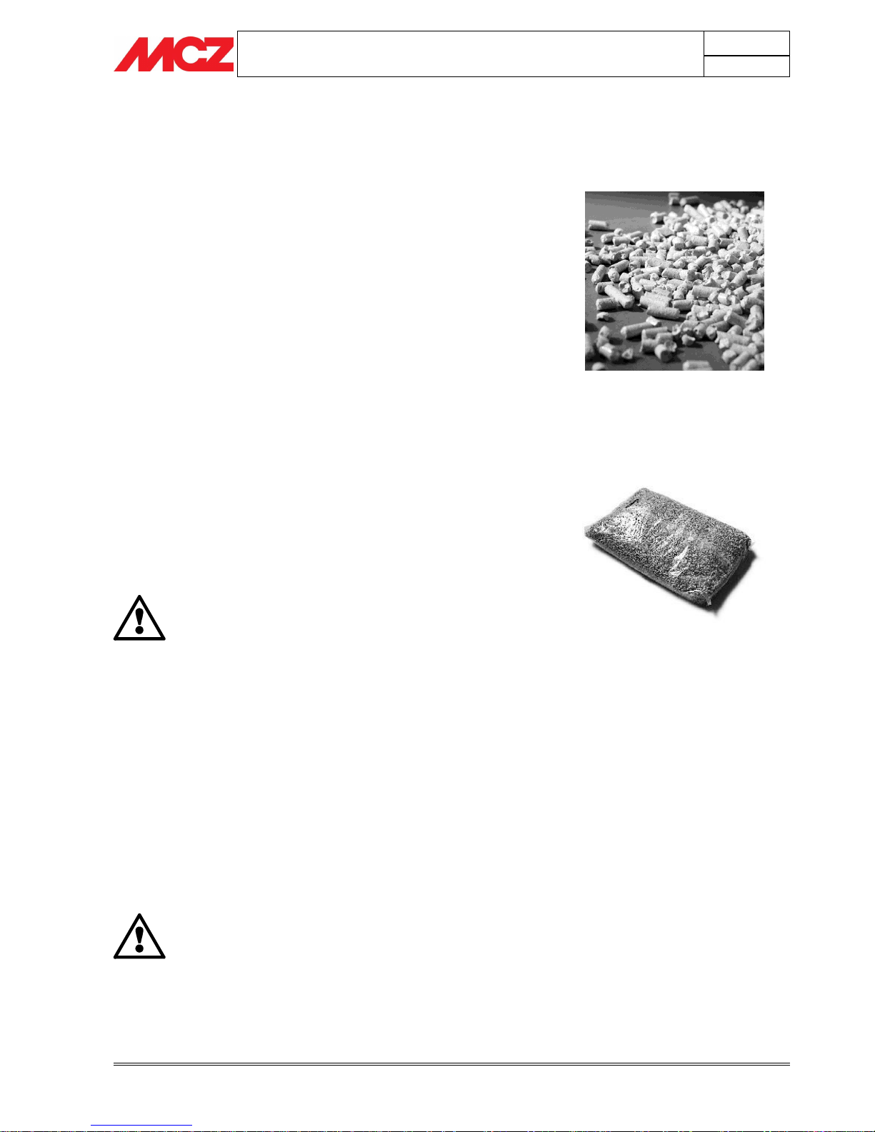
Wood pellets are manufactured by hot-extruding compressed sawdust which
is produced during the working of natural dried wood. The compactness of the
material comes from the lignin which is contained in the wood itself, and
allows the production of pellets without the use of glues or binders.
The market offers different types of pellet with characteristics which
vary depending on what mixture of woods is used. The diameter varies
between 6 mm and 8 mm, with a standard length in the range ¼” to 1
½”. Good quality pellets have less than 0.5% ash with a moisture
content which varies from 5% to 8% by weight.
Besides being an ecological fuel (exploiting timber residues to the
maximum and achieving cleaner combustion than is possible with fossil
fuels), pellets also have technical advantages. While good-quality timber
has a calorific power of 4.4 kW/kg (with 15% moisture, therefore after
about 18 months' seasoning), the equivalent figure for pellets is 5.3
kW/kg.
To ensure good combustion, the pellets must be stored in an area that
is free of humidity and protected from dirt. The pellets are usually
supplied in 40 lb. sacks, so storing them is very convenient.
Good quality pellets ensure good combustion, thus lowering the
emission of harmful agents into the atmosphere.
The poorer the quality of the fuel, the more
frequently cleaning will be necessary. Especially the
internal parts, such as the grate and the combustion
chamber.
The main certifications of quality for pellets in the European market are
DINplus and Ö-Norm M7135; these ensure respect of:
Calorific power: 4.9 kW/kg
Water content: max 10% of weight
Percentage of ashes: max 0,5% of weight
Diameter: 5 – 6mm
Length: max 30mm
Contents: 100% untreated wood, with no added bonding
substances (bark percentage 5% max)
Packaging: in sacks made from ecologically compatible or
biologically decomposing material
MCZ strongly recommends using certified premimun
quality pellet fuel in its stoves
The use of poor quality high ash fuel compromises
the running of your stove and could void the
warranty.
MCZ pellet stoves run exclusively on pellets with a
diameter of 6-8 mm with lengths from ¼” to 1 ½”.
Fuel pellets

PELLET STOVES
Chapter 2
INSTALLATION AND USE MANUAL
page 10
Theoretical notions for installation
Technical service - Rights reserved MCZ S.p.A. - Reproduction prohibited
4
15.5 In²
40”
3”
3”
2.2. INSTALLATION
IMPORTANT!
Installation and assembly of the stove must be
carried out by qualified personnel.
The stove must be installed in an area with adequate space to allow the
stove to be cleaned and maintained.
The stove must be positioned in such a way that the plug is accessible.
The site must be:
Provided with enough make up air for proper operation of the
stove.
Have a properly grounded 110V outlet within 6‟
Installation and repair of the Ego/Star Pellet Stove should be done by a
qualified service person. The appliance should be inspected by a
qualified service person before use and at least annually. Every 2000
hours of effective work a temporary service warning appears in display
at each ignition, to remind the requirement of a periodical inspection. It
is imperative that control compartments, burners, and circulating air
passageways of the Ego/Star be kept clean.
2.3. OPERATING AREA
For proper operation and a good heat distribution, the stove must have
adequate make up air. This can be supplied by connecting the outside
air supply or by assuring that there is adequate ventilation in the home.
In bedroom or bathroom installations the outside air
connection is required!
Locating the stove in a room with an explosive
atmosphere is prohibited.
If the walls are not flammable, position the stove with a clearance to
the rear of at least 2,5”.
For flammable walls, keep a minimum distance of 5” at the rear, 4” on
the sides and 40” at the front.
If the room contains objects which are believed to be particularly
delicate, such as drapes, sofas and other furniture, their distance from
the stove should be considerably increased. See page 16 for details.
If the flooring is made of wood, provide a floor
protection surface in compliance with current
national standards.
2.4. CONNECTION TO THE EXTERNAL AIR INTAKE
It is essential that at least as much air must be able to flow into the
room where the stove is installed as is required for proper combustion
in the appliance and for the ventilation of the room. This can be
accomplished by connecting the outside air feature on the stove or by
providing a ventilated wall pass through 15 sq in min.
The air intake must:
Example of pellet stove installation
Example of pellet stove installation
PELLET STOVES
Chapter 2
INSTALLATION AND USE MANUAL
page 11
Theoretical notions for installation
Technical service - Rights reserved MCZ S.p.A. - Reproduction prohibited
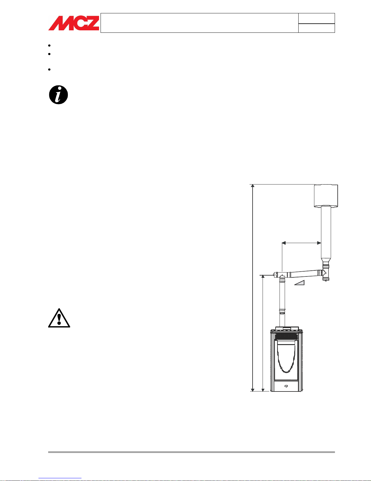
3-5 %
78.7” - 117” MAX
H
>
1
5
6
”
H
>
5
8
.
5
”
Directly provide air to the room where the stove is installed
Must be protected by a grill, metal mesh or suitable guard, as
long as this does not restrict air flow.
be positioned where it will not be obstructed
MCZ strongly reccommends to install the air filter
provided with the stove (see Page 29).
Connection to outside (see Page 29) is required for all
mobile home installations and where building codes
require.
In all the other cases it is not mandatory to connect
the air intake directly to the stove (so that it draws
air directly from outside), but it is essential to ensure
an airflow to the stove for proper operation.
2.5. CONNECTION TO THE FLUE PIPE
The stove must be connected to a UL listed pellet vent.
Pellet venting pipe (also known as L or PL vent) is constructed of two
layers with air space between the layers. This air space acts as an
insulator and reduces the outside surface temperature to allow a
clearance to combustibles of only 3 inches. The sections of pipe lock
together to form an air tight seal in most cases; however, in some
cases a perfect seal is not achieved. For this reason and the fact that
the Ego/Star operates with a positive vent pressure, we specify that the
joints also be sealed with high-temp silicone.
Connect the stove to listed 3” or 4” pellet vent. Be sure to use a starting
collar to attach the venting system to the stove. The starting collar
must be sealed to the stove with high temp silicone caulking.
Follow vent manufacturers instructions regarding clearances to
combustibles. At the bottom of the flue pipe, provide an inspection cap
to allow periodic inspection and cleaning, which must be done
annually.
IMPORTANT!
The stove must be connected to a flue pipe or an
internal vent system conforming to UL standards
Be sure to use approved pellet vent pipe wall and
ceiling pass-through fittings to go through
combustible walls and ceilings.
Follow manufacturers instructions regarding proper
installation of the flue system.
The Exhaust from the combustion of pellets may
cause discoloration on exterior walls. To eliminate
this possibility terminate the vent above the roof line.
Exhaust gasses are very hot and almost invisible.
They can cause burns on contact.
Example of pellet stove installation
PELLET STOVES
Chapter 2
INSTALLATION AND USE MANUAL
page 12
Theoretical notions for installation
Technical service - Rights reserved MCZ S.p.A. - Reproduction prohibited
A combustion blower is used to extract the combustion gases from the
firebox. This causes a negative pressure in the firebox and a positive
pressure in the venting system. The longer the vent pipe and more
elbows used in the system, the greater the flow resistance. Because of
these facts we recommend using as few elbows as possible and 20 feet
or less of vent pipe. The maximum horizontal run should not exceed 3
feet and must have a slope of not less than 3%. The vertical distance
between one 90‟ elbow or T connector and another must not be less
than 4 ½‟. If more than 20 feet of pipe is needed, the diameter should
be increased from 3" to 4" because a larger pipe causes less flow
resistance.
Using a draft gauge check that there is a minimum draft of 10 Pa when the
stove is burning at max level.
IMPORTANT! All sections of the venting must be
inspectable and removable to enable periodic
cleaning. All 90 degree elbows should be T
connectors to allow cleaning and inspection, which
must be done annually.
FOR CONNECTION TO THE FLUE PIPE, NOT MORE
THAN 3’ OF HORIZONTAL AND NOT MORE THAN
THREE 90° ELBOWS ARE ALLOWED
IT IS ALSO ADVISABLE TO USE 4” PELLET VENT FOR
RUNS OVER 20’ IN HEIGHT.
This type of connection ensures the ventilation of the
exhaust fumes in the event of a temporary power
outage.
Position the stove bearing in mind all the instructions and considerations
above.
See Page 18 for further details of vent configurations.
PELLET STOVES
Chapter 2
INSTALLATION AND USE MANUAL
page 13
Theoretical notions for installation
Technical service - Rights reserved MCZ S.p.A. - Reproduction prohibited
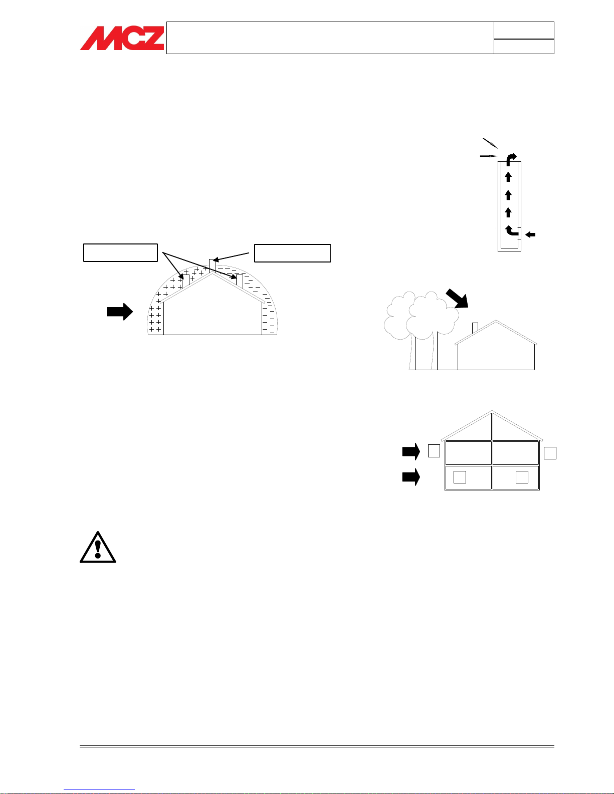
2.6. OPERATING PROBLEMS CAUSED BY DRAUGHT
DEFECTS IN THE FLUE
Of all the weather and geographical conditions which affect the
operation of a flue pipe (rain, fog, snow, altitude a.s.l., exposure to
sunlight, direction of facing), the wind is unquestionably the most
decisive. In fact, along with thermal depression caused by the
difference in temperature inside and outside of the chimney, there is
another type of depression or over-pressure: dynamic pressure caused
by the wind. An updraft always increases depression and hence
draught. A crosswind increases depression provided the cowl has been
installed properly. A downdraft always decreases depression, at times
inverting it.
Besides the direction and force of the wind, the position of the flue and
the cowl with respect to the roof of the building and the surrounding
landscape is important.
The wind also influences the operation of the chimney indirectly by
creating high-pressure and low-pressure zones, not only outside the
building but inside as well. In rooms directly exposed to the wind (2),
an indoor high-pressure area can be created which can augment the
draught in stoves and fireplaces, but it can be counteracted by the
external high pressure if the cowl is situated on the side exposed to the
wind (1). On the other hand, in the rooms on the opposite side from
the direction of the wind (3), a dynamic depression can be created
which competes with the natural thermal depression developed by the
chimney, but this can be compensated for (sometimes) by locating the
flue on the opposite side from the direction of the wind (4).
IMPORTANT! The operation of the pellet stove is
noticeably sensitive to the conformation and position
of the flue which is adopted.
Hazardous conditions can only be overcome by
suitable setting-up of the stove carried out by
qualified MCZ personnel.
E.g. Downdraft at 45° of
8m/sec. Overpressure of 17
Pa
Least favourable points
Most favourable position
WIND
Downdraft
High-pressure zone
Low-pressure zone
E.g. Crosswind 2: 8 m/sec
Depression of 30Pa
1
2 3
4
1-2 = High-pressure zones
3-4 = Low-pressure zones
WIND
PELLET STOVES
Chapter 3
INSTALLATION AND USE MANUAL
page 14
Installation and fitting
Technical service - Rights reserved MCZ S.p.A. - Reproduction prohibited
3. INSTALLATION AND ASSEMBLY
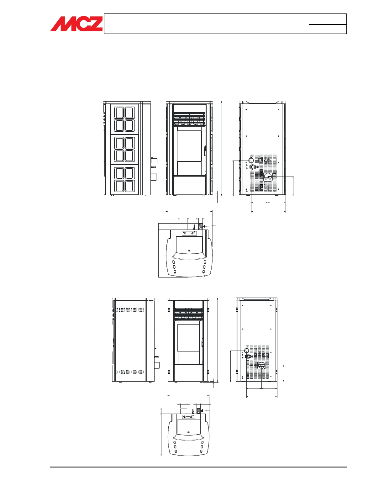
3.1. DRAWINGS AND TECHNICAL CHARACTERISTICS
3.1.1. STAR Air
4
1
.
1
5
1
5
.
3
1
7.29
7.61
15.02
8
.
1
9
20.28
2
.
7
3
2
0
.
6
7
Ø3.12
Ø1.87
1
1
FILTER
3.1.2. EGO Air
4
1
.
1
5
1
5
.
3
1
7.29
7.72
15.02
8
.
3
1
20.28
Ø3.12
Ø1.87
2
.
7
3
2
0
.
6
7
1
1
FILTER
PELLET STOVES
Chapter 3
INSTALLATION AND USE MANUAL
page 15
Installation and fitting
Technical service - Rights reserved MCZ S.p.A. - Reproduction prohibited
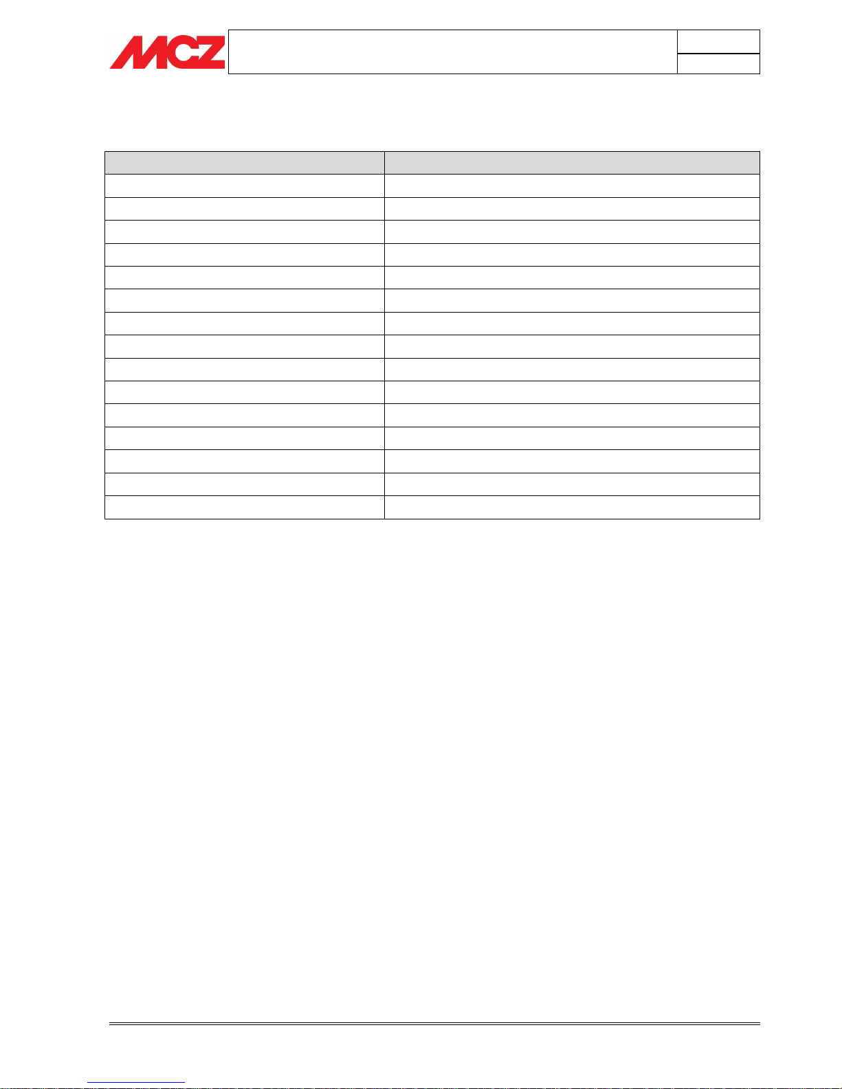
3.1.3. Technical characteristics
Technical characteristics
EGO – STAR Mod. AIR
Nominal power (Max)
31.500 BTU
Reduced power (Min)
10.500 BTU
Efficiency
>78%
Smoke Temperature at Max
180°C
Smoke Temperature at Min
90°C
Suggested draft at nominal power
0,12 mbar – 12 Pa
Suggested draft at reduced power
0,06 mbar – 6 Pa
Pellet hopper capacity
37 litres
Pellet type
diameter 6-8 mm / length 5-30 mm
Pellet consumption per hour
Min ~ 0,6 kg/h * Max. ~ 1,7 kg/h *
Ignition electrical power
420 Watt
Mean electrical power
80 Watt
Power supply frequency and voltage
110 Volts / 60 Hz
Net weight
140 Kg.
Weight with packaging
150 Kg.
* Data that may vary depending on the type of pellets used.
PELLET STOVES
Chapter 3
INSTALLATION AND USE MANUAL
page 16
Installation and fitting
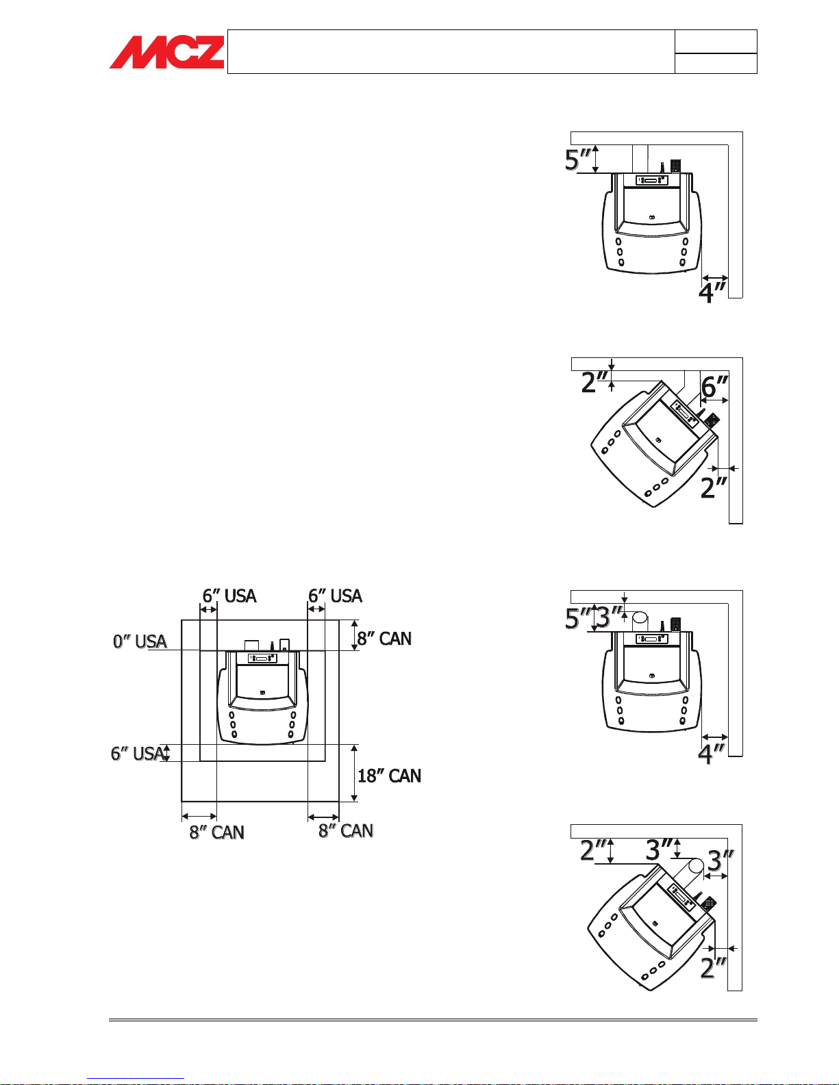
Technical service - Rights reserved MCZ S.p.A. - Reproduction prohibited
PARALLEL INSTALLATION
BACKWALL VENT EXIT
CORNER INSTALLATION
BACKWALL VENT EXIT
PARALLEL INSTALLATION
CEILING VENT EXIT
CORNER INSTALLATION
CEILING VENT EXIT
FLOOR PROTECTOR
3.2. INSTALLATION
When installing and operating your MCZ Ego/Star Pellet Stove, respect
basic safety standards. Read these instructions carefully before you
attempt to install or operate the Ego/Star. Failure to do so may result in
damage to property or personal injury and may void the product
warranty. Consult with your local building code agency and insurance
representative before you begin your installation to ensure compliance
with local codes, including the need for permits and follow-up
inspections. Several issues must be addressed when selecting a suitable
location for your Ego/Star Pellet Stove. Observing required clearances to
combustible materials, the proximity to a safe chimney or venting
system, and the accessibility of electrical supply must all be considered.
In addition, selecting a location that takes advantage of the building's
natural air flow is also desirable to maximize the heating effectiveness
of the heater. In many cases, this is a central location within the
building. Adequate combustion and ventilation air must be provided.
See Page 11 about venting.
Place the stove on a noncombustible floor surface. If the floor surface is
made of a combustible material, (such as carpet, vinyl or wood), a floor
protector must be installed between the bottom of the unit and the
floor. The floor protector must be 3/8 inch minimum thickness of noncombustible material extending beneath the heater and extending to
the front, side, and rear as indicated in the figure below. Place the
stove away from combustible walls at least as far as shown in the
pictures on the right side for different installation conditions. Note that
the clearances shown are minimum for safety but do not leave much
room for access when cleaning or service is needed.
3.2.1. Alcove installation
As follows the minimum distances for an alcove installation:
Min. Alcove Height: 60”
Min.Alcove Side Wall to appliance: 4”
Max.Alcove Depth: 34”
PELLET STOVES
Chapter 3
INSTALLATION AND USE MANUAL
page 17
Installation and fitting
Technical service - Rights reserved MCZ S.p.A. - Reproduction prohibited
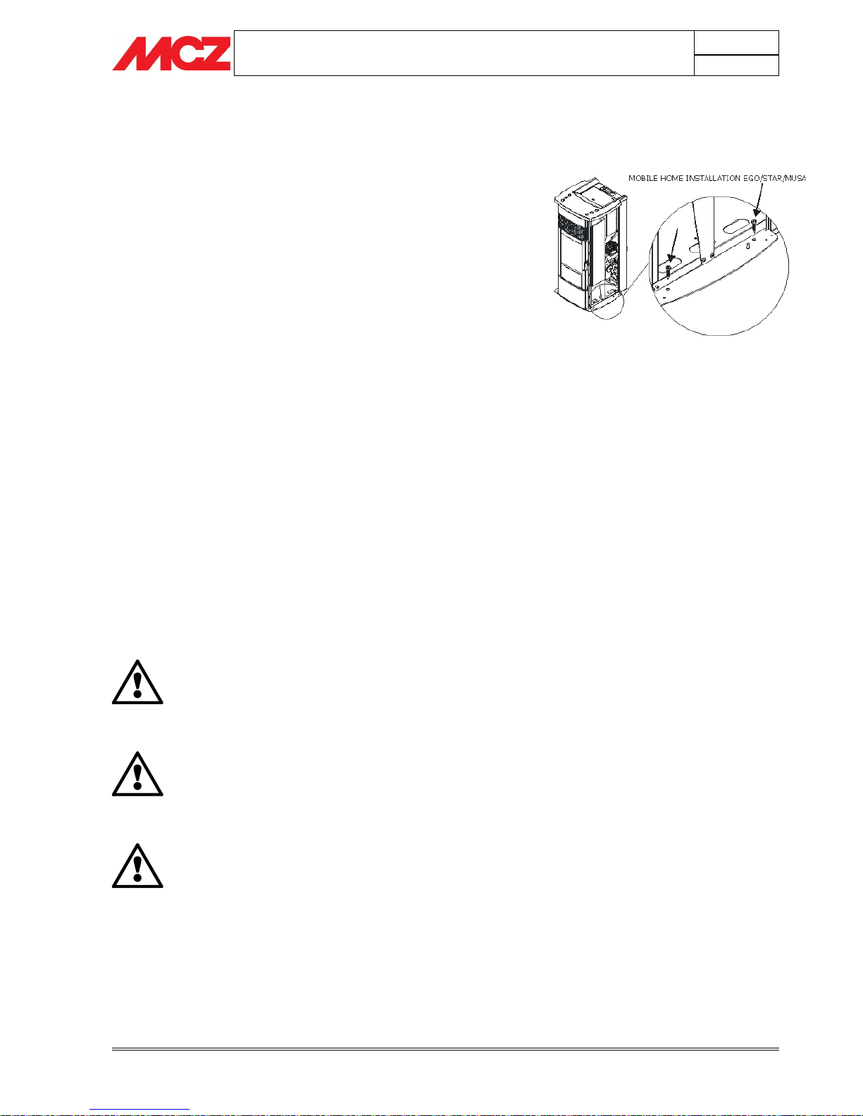
3.3. MOBILE HOME INSTALLATION
When installing the Ego/Star in a mobile home several requirements
must be followed:
1. The unit must be bolted to the floor. This can be done with 1/4" lag
screws through the 2 holes in the base plate shown in figure
2. The unit must also be connected to outside air (See page 29).
3. Floor protection and clearances must be followed as shown on page
16.
4. Unit must be grounded to the metal frame of the mobile home.
CAUTION: In mobile home installations the appliance must be
vented to the outside. The user must routinely inspect the point
where air is drawn in to insure that it is clear of leaves/debris
and ice or snow.
Due to high temperatures, the Ego/Star should be placed out of traffic
and away from furniture and draperies. Children and adults should be
alerted to the hazards of high surface temperatures and should stay
away to avoid burn to skin and/or clothing. Young children should be
carefully supervised when they are in the same room as the stove.
Clothing and other flammable materials should not be placed on or near
the Ego/Star Pellet Stove.
Mobile/manufactured home regulations do not allow
installation in rooms designated for sleeping.
Mobile home installation should be done in accordance with the
manufactured home and Safety Standard (hud), CFr 3280, Part
24.
THE STOVE IS HOT WHILE IN OPERATION. KEEP
CHILDREN, CLOTHING AND FURNITURE AWAY.
CONTACT MAY CAUSE SKIN BURNS.
KEEP COMBUSTIBLE MATERIALS SUCH AS GRASS,
LEAVES, ETC. AT LEAST 3 FEET AWAY FROM THE
POINT DIRECTLY UNDER THE VENT TERMINATION.
THE STRUCTURAL INTEGRITY OF THE MOBILE HOME
FLOOR, WALL, AND CEILING/ROOF AND THE
EFFECTIVENSS OF ALL VAPOR BARRIERS WITHIN
THE STUCTURE MUST BE MAINTAINED
Floor fixing of the appliance

PELLET STOVES
Chapter 3
INSTALLATION AND USE MANUAL
page 18
Installation and fitting
Technical service - Rights reserved MCZ S.p.A. - Reproduction prohibited
3.4. VENTING
3.4.1. Avoiding Smoke and Odors
Negative Pressure, Shut-down, and Power Failure:
To reduce the probability of back-drafting or burn-back in the
pellet burning appliance during power failure or shut-down
conditions, the stove must be able to draft naturally without
exhaust blower operation. Negative pressure in the house will resist this
natural draft if not accounted for in the pellet appliance installation.
Heat rises in the house and leaks out at upper levels. This air must be
replaced with cold air from outdoors, which flows into lower levels of
the house. Vents and chimneys into basements and lower levels of the
house can become the conduit for air supply, and reverse under these
conditions.
3.4.2. Vent Configurations
To reduce probability of reverse drafting during shut-down conditions,
MCZ strongly recommends:
• Installing the pellet vent with a minimum vertical run of five feet,
preferably terminating above the roof line.
• Installing the outside air intake at least four feet below the vent
termination.
To prevent soot damage to exterior walls of the house and to prevent
re-entry of soot or ash into the house:
• Maintain specified clearances to windows, doors, and air inlets,
including air conditioners.
• Vents should not be placed below ventilated soffits. Run the vent
above the roof.
• Avoid venting into alcove locations.
• Vents should not terminate under overhangs, decks or onto covered
porches.
• Maintain minimum clearance of 12 inches from the vent termination to
the exterior wall. If you see deposits developing on the wall, you may
need to extend this distance to accommodate your installation
conditions.
MCZ assumes no responsibility for, nor does the warranty
extend to, smoke damage caused by reverse drafting of pellet
appliances under shut-down or power failure conditions.
PELLET STOVES
Chapter 3
INSTALLATION AND USE MANUAL
page 19
Installation and fitting
Technical service - Rights reserved MCZ S.p.A. - Reproduction prohibited
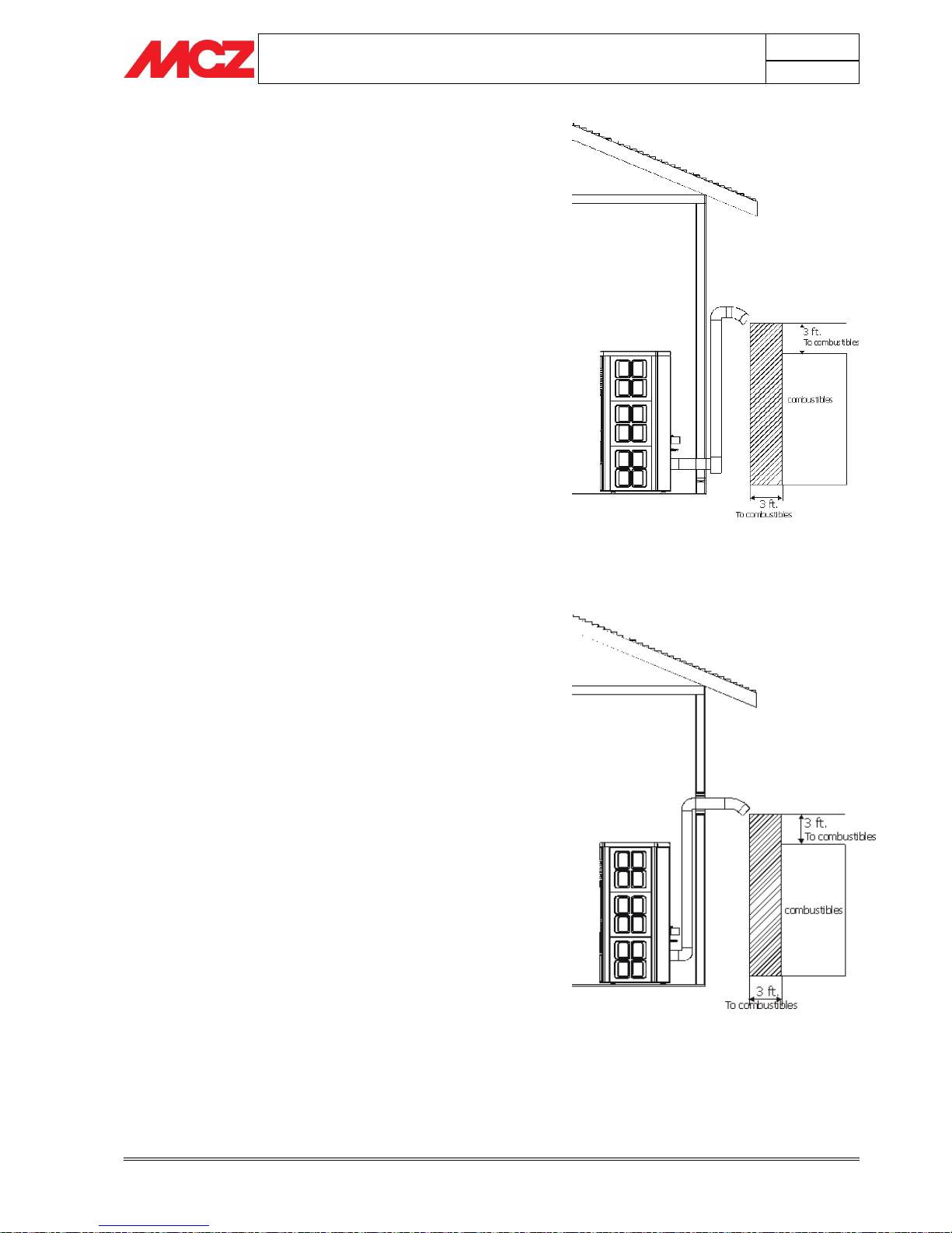
3.4.2.1. Wall outlet (method #1)
This method provides excellent venting for normal operation and
allows the stove to be installed closest to the wall. Two and a half
inches from the wall is safe; however, three inches allows better
access to remove the rear panel. The vertical portion of the vent
should be three to five feet high. This vertical section will provide
natural draft in the event of a power failure. Note: do not place
joints within wall pass-throughs.
3.4.2.2. Wall outlet (method #2)
This method also provides excellent venting for normal operation
but requires the stove to be in-stalled farther from the wall. The
vertical portion of the vent should be three to five feet high and
at least three inches from a combustible wall. This vertical section
will provide natural draft in the event of a power failure. Note: do
not place joints within wall pass-throughs.
PELLET STOVES
Chapter 3
INSTALLATION AND USE MANUAL
page 20
Installation and fitting
Technical service - Rights reserved MCZ S.p.A. - Reproduction prohibited
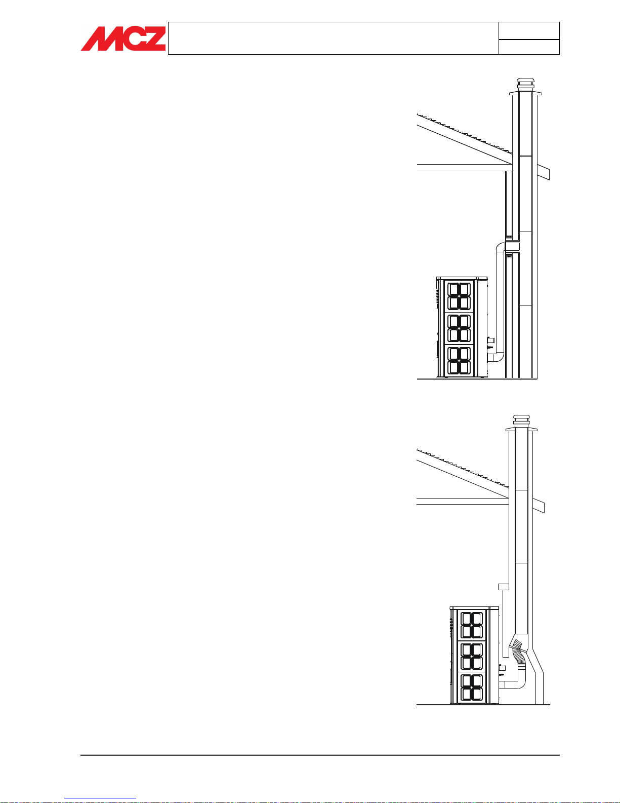
3.4.2.3. Installing into an existing chimney (method #3)
This method provides excellent venting for normal operation. Check
your local code requirements. Some areas require that a liner be
installed to the top of the flue, as shown in method method #6. This
method will provide natural draft in the event of a power failure. If the
chimney condition is questionable or if the flue size is larger than 8 X 8
inches, you should refer to method #6. If choosing this method,
increase the vent pipe to 4 in. at the stove.
3.4.2.4. Installing into an existing fireplace chimney (method #4)
This method provides excellent venting for normal operation. Check
your local code requirements. Some areas require that a liner be
installed to the top of the flue, as shown in method #5. This method
also provides natural draft in the event of a power failure. The damper
area must be sealed with a steel plate or fiberglass. A cap should be
installed on the chimney to keep out rain. If the chimney condition is
questionable or if the flue size is larger than 8 X 8 inches, you should
refer to Method #5. If choos-ing this method, increase the vent pipe to
4 in. at the stove.
PELLET STOVES
Chapter 3
INSTALLATION AND USE MANUAL
page 21
Installation and fitting
Technical service - Rights reserved MCZ S.p.A. - Reproduction prohibited
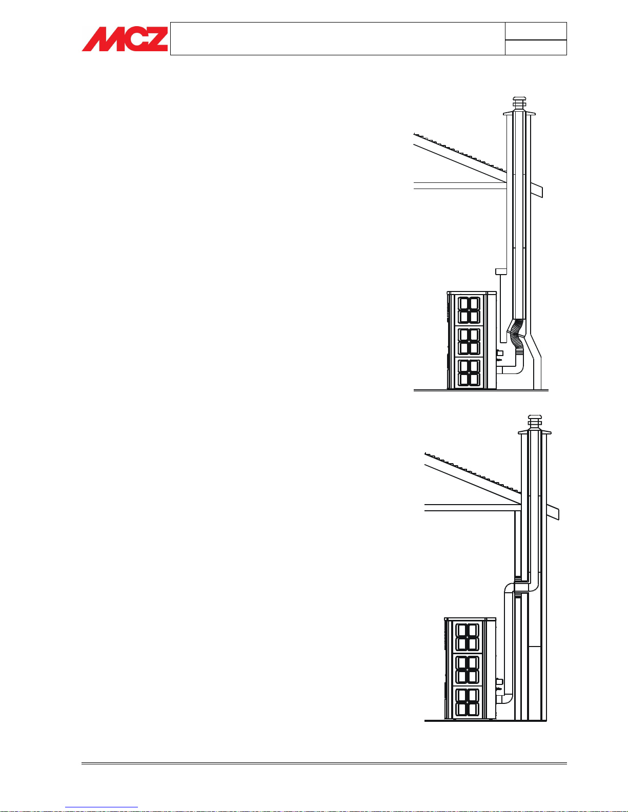
3.4.2.5. Installing into an existing fireplace chimney (method #5)
This method provides excellent venting for normal operation. This
method also provides natural draft in the event of a power failure.
Some places in the US and Canada, it is required that the vent pipe
extend all the way to the top of the chimney. In this method a cap
should also be installed on the chimney to keep out rain. Be sure to use
ap-proved pellet vent pipe fittings. Seal pipe joints with silicone in
addition to the sealing method used by the manufacturer. Pipe size
should be increased to 4" using this method.
3.4.2.6. Installing into an existing chimney (method #6)
This method provides excellent venting for normal operation. This
method also provides natural draft in the event of a power failure.
Some places in the US and Canada, it is required that the vent pipe
extend all the way to the top of the chimney. The pipe or liner inside
the chimney should be 4" diameter and approved for pellet venting.In
this method a cap should also be installed on the chimney to keep out
rain.
 Loading...