

UK
INSTALLATION
AND USE MANUAL

INSTALLATION AND USE MANUAL
SCENARIO
Index
pag.
2
INTRODUCTION....................................................................................................................................3
1. WARNINGS AND WARRANTY CONDITIONS .....................................................................................4
1.1. SAFETY WARNINGS........................................................................................................................4
1.2. GUARANTEE CONDITIONS ..............................................................................................................4
1.2.1. Exclusions................................................................................................................................4
2. SCENARIO CLADDING TECHNICAL DATA (MEASUREMENTS IN CM)................................................6
2.1. SCENARIO GAS LEFT ......................................................................................................................6
2.2. SCENARIO GAS RIGHT....................................................................................................................6
2.3. SCENARIO WOOD LEFT...................................................................................................................7
2.4. SCENARIO WOOD RIGHT................................................................................................................7
3. SCENARIO CLADDING ASSEMBLY.....................................................................................................8
3.1. SCENARIO CLADDING COMPONENTS...............................................................................................8
3.2. POSITIONING THE CLADDING FRAME..............................................................................................8
3.3. PREPARING CONNECTION OF TV AND DEVICES................................................................................9
3.3.1. Electrical connections to the domestic system...........................................................................10
3.3.2. TV installation and electrical connections..................................................................................10
3.3.3. Connections in the drawer.......................................................................................................11
3.3.4. Using the IR repeater .............................................................................................................12
3.4. POSITIONING FIREPLACE STOVE FORMA 95 GAS............................................................................12
3.5. POSITIONING FIREPLACE STOVE VIVO 90 WOOD...........................................................................13
3.6. ASSEMBLING THE INSULATING PANELS.........................................................................................14
3.7. GAS SCENARIO GLASS ALIGNMENT................................................................................................15
3.8. WOOD SCENARIO GLASS ALIGNMENT............................................................................................16
3.9. ASSEMBLING THE PLASTERBOARD CLADDING................................................................................17
3.10. ASSEMBLING THE GAS FRAME ...................................................................................................18
3.11. ASSEMBLING THE WOOD FRAME................................................................................................19
3.12. SHELF ASSEMBLY......................................................................................................................20
Index Technical service – all rights reserved by MCZ
GROUP spa. Reproduction prohibited

INSTALLATION AND USE MANUAL
SCENARIO
INTRODUCTION
Dear Customer,
Thank you for your preference in choosing an MCZ product, specifically
a Scenario cladding.
We are sure that, by using it, you will appreciate the quality of an
accurately designed and tested product. Our goal is to combine
technology with easy of use and, above all, safety.
In order for the Scenario cladding to work properly and to be
able to fully enjoy the heat and sense of wellbeing it may
diffuse in your home we suggest that you carefully read this
use and maintenance manual before using the product for the
first time; please contact your dealer should you require
assistance in resolving any doubts or problems.
Congratulations on your choice and remember, the fireplace stove
MUST NEVER be used by children who should always be kept at a
safe distance!
Revisions to the publication
In order to improve the product, the Manufacturer reserves the right to
modify and update this publication without prior notice.
Reproduction, even partial, of this manual without the Manufacturer's
authorisation is prohibited.
Manual preservation
• Please take care of this manual and keep it in a place that can be
quickly and easily reached.
• this manual should be lost or destroyed, or if it is in poor condition,
request a copy from your dealer or directly from the manufacturer,
providing product identification data.
Introduction
pag.
3
Introduction Technical service – all rights reserved by MCZ GROUP
Spa. Reproduction prohibited

INSTALLATION AND USE MANUAL
SCENARIO
1. WARNINGS AND WARRANTY CONDITIONS
1.1. SAFETY WARNINGS
• Check the conditions of the surface that will support the
weight of the stove. If it is made of flammable material
(such as wood, carpet, or plastic) provide suitable
insulation.
• The user is fully liable for improper product use,
releasing MCZ from any civil or penal liabilities.
• Any tampering with the fireplace stove, or use of non
original spare parts, may be hazardous to the user and
releases MCZ from any civil or penal liability.
• Incorrect installations or poor maintenance (not
compliant with the provisions of this manual) may cause
damage to persons, animals or property. MCZ is not
civilly or criminally liable in this cases.
Chapter 1
pag.
4
1.2. GUARANTEE CONDITIONS
MCZ guarantees the product, with the exception for the elements
subject to normal wear listed below, for two years from the date of
purchase that is proven by a document that indicates the dealer's name
and date of sale, if the completed warranty certificate was returned
within 8 days and if the product was installed and inspected by a
specialised installation technician and according to the detailed
instructions indicated in the instruction manual supplied with the
product.
The warranty includes the free replacement or repair of parts
recognised as factory defective.
1.2.1. Exclusions
The guarantee does not cover any part that may be defective
due to negligence or careless use, incorrect maintenance,
installation non compliant with that specified by MCZ.
MCZ refuses to accept any responsibility for any damage which may be
caused, directly or indirectly, by persons, animals or things as a result
of the failure to observe all the provisions set forth in the instruction
booklet, especially those concerning warnings on the subject of
installation, use and maintenance of the appliance.
In the event of product inefficiency, please contact your dealer and/or
area importer.
Damages caused by transport and handling are not covered by the
guarantee.
Exclusively refer to the supplied manual for product installation and
use.
The guarantee will be invalidated in the event of damage caused by
tampering with the appliance, atmospheric agents, natural disasters,
electrical discharges, fire and lack of, or incorrect, maintenance in
terms of the manufacturer's instructions.
Chapter 1
Technical service – all rights reserved by MCZ
GROUP spa. Reproduction prohibited

INSTALLATION AND USE MANUAL
SCENARIO
Chapter 1
pag.
5
REQUEST FOR SERVICE
Requests for service must be addressed to the dealer
who shall forward the request to the MCZ technical
assistance service.
MCZ in not liable in the event the product and any
other accessory is improperly used or modified
without authorisation.
Only original MCZ spare parts must be used for all
replacements.
Chapter 1
Technical service – all rights reserved by MCZ
GROUP spa. Reproduction prohibited
INSTALLATION AND USE MANUAL Chapter 2
pag.
SCENARIO
6
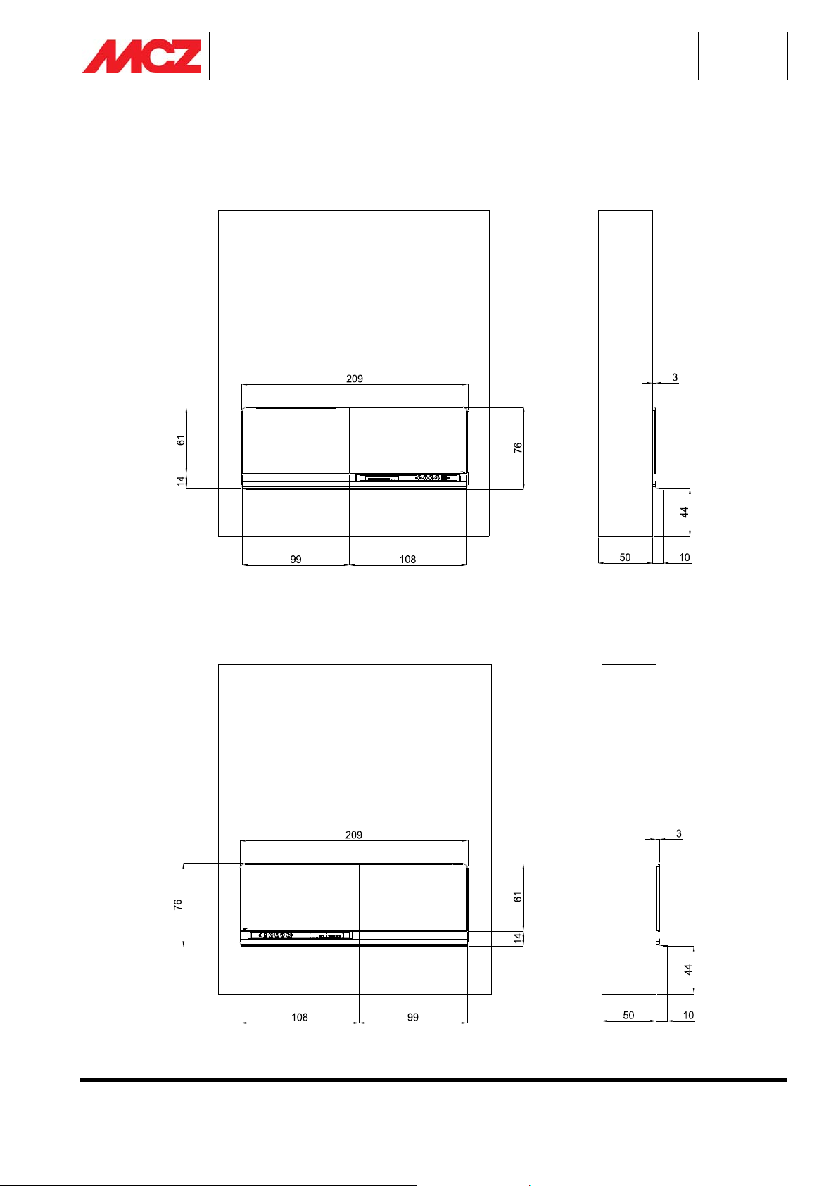
2. SCENARIO CLADDING TECHNICAL DATA (MEASUREMENTS IN cm).
2.1. SCENARIO GAS LEFT
GAS TV
2.2. SCENARIO GAS RIGHT
TV GAS
Chapter 2 Technical service – all rights reserved by MCZ
GROUP spa. Reproduction prohibited
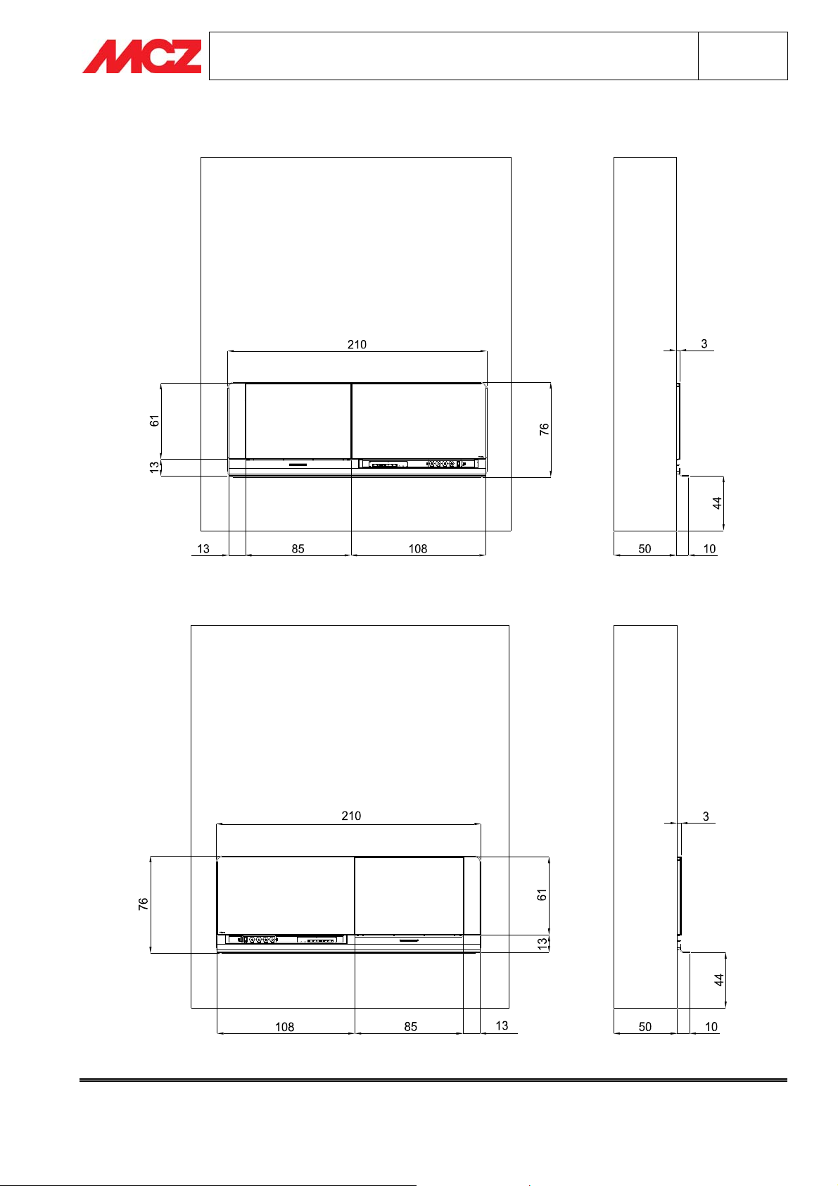
2.3. SCENARIO WOOD LEFT
WOOD TV
INSTALLATION AND USE MANUAL Chapter 2
pag.
SCENARIO
7
2.4. SCENARIO WOOD RIGHT
TV WOOD
Chapter 2 Technical service – all rights reserved by MCZ
GROUP spa. Reproduction prohibited

INSTALLATION AND USE MANUAL Chapter 2
SCENARIO
3. SCENARIO CLADDING ASSEMBLY
For the Scenario cladding to be properly installed we recommend you follow the assembly
sequences in order as listed in the manual.
3.1. SCENARIO CLADDING COMPONENTS
The cladding must always be kept upright and exclusively moved with a trolley. You must
be particularly careful to prevent the components contained in the package from
mechanical blows comprising their integrity. Moving the product must always be done
with care. If possible, unpack the product neat to the area where it is to be installed.
The materials which make up the packaging are not toxic or harmful, so no special
procedures for disposal are required. Their storage, disposal or possible recycling are
therefore the responsibility of the final user, in compliance with current legislation on the
subject. Do not store Scenario cladding without the relative packing.
The cladding is delivered on one sole package containing:
-A: cladding frame (already in the left or right version),
-B: package containing the LCD LOEWE television,
-C: package containing the aesthetic glass,
-D: package containing the insulating panels,
-E: aesthetic frame,
-F: shelf.
pag.
8
3.2. POSITIONING THE CLADDING FRAME
Position the frame in the place chosen for installation and adjust it to level by screwing and unscrewing the
dedicated feet.
The frame is to be secured to the floor and wall or only to a wall, Mcz recommends always securing the frame in
the lower part (floor or wall) and the upper part.. To anchor the frame to the floor secure brackets “X” using the
apposite brass plugs and screws supplied. To anchor the frame to the wall secure brackets “X” using the apposite
brass plugs and screws supplied.
Example of cladding left
Chapter 2 Technical service – all rights reserved by MCZ
GROUP spa. Reproduction prohibited

INSTALLATION AND USE MANUAL Chapter 2
pag.
SCENARIO
9
3.3. PREPARING CONNECTION OF TV AND DEVICES
Before assembling the Scenario cladding, perform the preparations for the domestic
system in order to make all the devices work which you wish to use.
MCZ SHALL NOT BE LIABLE FOR DAMAGE CAUSED BY INCORRECT CONNECTIONS OR
THOSE CARRIED OUT BY UNQUALIFIED PERSONNEL
The TV supplied is prepared for connection with various devices using the wiring provided, already mounted in
the cladding frame, which should be connected to the back of the LOEWE TV and domestic system.
Diagram of supplied wiring
The terminals with the letter “A” must be wired to the LOEWE TV, the terminals with the letter “B” are wired to
the drawer and the terminals with the letter “C” are to be wired to the domestic system. The table below lists the
terminals to be wired.
POS. TERMINAL POS. TERMINAL
1A Male IR repeater socket 1B Female IR repeater socket
2A Male white/red RCA 2C Male white/red RCA
3A Schuko three-pole plug 3B Schuko plug
4A Male HDMI 1 4B Male HDMI 1
5A Male HDMI 2 5B Male HDMI 2
6A Male VGA 5B Female VGA
7A Male USB 7B Female USB
8A Male TV antenna 8B Male TV antenna
9C Telephone 9B Telephone
10C Male TV antenna 10B Female TV antenna
11C SAT antenna 11B SAT antenna
12A SAT antenna 12B SAT antenna + male connector
Using these cables it is possible to connect to the TV:
-a satellite decoder (prepared for satellite antenna and telephone cable for Pay TV),
- DVD readers (connection to the TV through HDMI technology),
- USB keys, cameras, video cameras, MP3 readers (connection through USB port),
-Dolby surround, home theatre (preparation with RCA attachments),
-personal computer (the TV can become a PC monitor through VGA cable).
Chapter 2 Technical service – all rights reserved by MCZ
GROUP spa. Reproduction prohibited

INSTALLATION AND USE MANUAL Chapter 2
pag.
SCENARIO
10
3.3.1. Electrical connections to the domestic system
After having chosen the desired position for installing the cladding, it is necessary to prepare all the primary
connections so that all the products you wish to use work correctly.
Indispensable preparations:
-230V power supply socket
- analogue TV socket
- satellite antenna socket (for using a Pay-tv satellite decoder or display satellite programmes)
- telephone socket (if you wish to use Pay TV or internet in the case of connection to a PC)
- RCA sockets (if you wish to connect the TV to a stereo or Dolby surround system).
3.3.2. TV installation and electrical connections
Using the 6 screws supplied (shown by an arrow in
the image to the side) assemble the LOEWE TV in the
lowest position permitted by the slots on the LCD
support.
By opening and closing the drawer a few times, check
that sliding is not impeded. If there is an impediment,
loosen the fixing screws and lift the LCD until the
interference with the drawer is eliminated. Connect all
the wiring terminals indicated with letter “A” (see
wiring diagram) to the prearrangements on the back
of the LOEWE TV as in the following image.
Chapter 2 Technical service – all rights reserved by MCZ
GROUP spa. Reproduction prohibited

INSTALLATION AND USE MANUAL Chapter 2
pag.
SCENARIO
11
3.3.3. Connections in the drawer
The drawer is equipped with a multiple socket with 3 free power supply positions (the 230V-1 is wired to the TV
power supply) including a main switch (I/O) which is for cutting voltage from the LOEWE TV and all the devices.
Drawer front view
EXAMPLES OF INSTALLING THE DEVICES:
Installation of satellite decoder: connect the decoder to
1- one of the free power supply sockets on the multiple socket,
2-one of the two HDMI cables (4B or 5B),
3- satellite antenna cable (11B), to do this you need to disconnect cables 11B+12B (standard connections),
4- telephone socket (9B) when a Pay TV service is used.
DVD reader installation
1- one of the free power supply sockets on the multiple socket,
2-one of the two HDMI cables (4B or 5B),
3- IN antenna (10B) and OUT antenna OUT (8B) cables if the reader is also a recorder
LOEWE TV installation
supply sockets on the multi socket unit. If you are not using an external device (when the domestic antenna is
connected to the DVD sending the signal to the TV) to connect the television directly to the antenna simply
connect the IN antenna (10B) cable with the OUT antenna (8B) cable. In order to use the Satellite Decoder
integrated with the LOEWE TV connect the satellite antenna cable from the domestic system with the cable
terminal 11C and check that terminals 11B and 12B are connected between them.
: connect reader to
: check that the television power supply cable (3B) is connected to one of the free power
Chapter 2 Technical service – all rights reserved by MCZ
GROUP spa. Reproduction prohibited

Once installation is complete we recommend checking that the TV and all the connected
devices work properly before proceeding with the next phases.
Power supply to the television and devices is activated through the main switch “I/O”
located on the multi socket unit.
INSTALLATION AND USE MANUAL Chapter 2
SCENARIO
3.3.4. Using the IR repeater
Supplied with the LOEWE TV is an IR remote control
repeater (infra-red). The repeater is used when thee
device (DVD, Decoder, etc.) is hidden and not accessible
using the remote control. Install the repeater by
connecting its connectors with that blocked to the drawer
near to the position dedicated to the USB cable (position
7B). Then position the transmitter on the front of the
equipment to be commanded (see figure to the side)
corresponding with its IR receiver. Such procedure will
allow the device to be controlled by its own remote control
by aiming the latter at the integrated television.
pag.
12
3.4. POSITIONING FIREPLACE STOVE FORMA 95 GAS
Remove the fireplace from its packaging, take out the external frame and the two aluminium covered steel
brackets by unscrewing the screws shown in figure1 (both sides) and check that the telescopic legs, shown by
the arrows on image 2, are blocked on the second hole starting from the bottom. Check that the adjustable feet
are fully screwed in. Unscrew the electro-valve from the fireplace stove structure (figure 3). Slide the fireplace
stove into position from the top of the frame being careful not to damage the electro-valve, over the apposite
brackets assembled on the cladding frame and proceed with levelling the fireplace respect to the measurements
shown in figure 4. At the end block the fireplace using the apposite brackets in the position shown in figure 5
and proceed with installing the flue pipe, connecting the gas system and preparing for ventilation (natural or
enforced) as described in the fireplace stove use and maintenance manual.
1
2
Chapter 2 Technical service – all rights reserved by MCZ
GROUP spa. Reproduction prohibited

INSTALLATION AND USE MANUAL Chapter 2
pag.
SCENARIO
13
Fireplace front
3
4
5
3.5. POSITIONING FIREPLACE STOVE VIVO 90 WOOD
TV side
Extract the fireplace from its packaging, position it onto the adjustable feet assembled on the cladding and
proceed with levelling the fireplace (figure 1) according to the measurements shown in figure 2. Once levelled
and the measurements checked, lock the feet locking units and block the fireplace stove to the crosspiece
assembled to the cladding frame using the screws shown in figure 3. Take the profiles packed near the frame.
Remove the screws that block the aluminate cover in the upper part of the fireplace stove (figure 4) and fit the
upper profile (bent part) above the cover, using the screws that were just removed. Open the fireplace stove's fire
door and fit the two side profiles, using the provided black screws (figure 4). Proceed with installing the chimney
flue and preparing for ventilation (natural or enforced) as described in the fireplace stove use and maintenance
manual.
TV side
1
Fireplace front
2
Chapter 2 Technical service – all rights reserved by MCZ
GROUP spa. Reproduction prohibited

INSTALLATION AND USE MANUAL Chapter 2
pag.
SCENARIO
14
3
4
3.6. ASSEMBLING THE INSULATING PANELS
Remove the insulating panels from the apposite packaging
and mount them to the cladding frame inside the
housings, following the sequence of the image to the side.
To assemble panel no. 3 loosen the locking screws on the
two brackets (S) which are located on the upper part of
the frame, insert the panel and tighten screws once again.
INSULATING PANEL SIZES:
400mm x 560mm x 25mm
12-
945mm x 495mm x 25mm
3-
400mm x 950mm x 25mm
Chapter 2 Technical service – all rights reserved by MCZ
GROUP spa. Reproduction prohibited

V
INSTALLATION AND USE MANUAL Chapter 2
pag.
SCENARIO
15
3.7. GAS SCENARIO GLASS ALIGNMENT
Take the television's aesthetic glass (the glass with the etched logo) and the fireplace glass out of the packaging.
Rest the glass support brackets onto the frame tabs (figure 1). Without tightening, screw in the supplied screws
so that the glass units are provisionally secured (figure 2). Adjust the perpendicularity of the glass units using
magnets located on the lower side of the supports (figure 3). Make sure that the distance between the two glass
units is 3 mm (figure 4) and adjust the horizontal alignment using the Stei screws mounted on the glass support
brackets (figure 5 ).
1
3
2
4
GAS T
5
Chapter 2 Technical service – all rights reserved by MCZ
GROUP spa. Reproduction prohibited

V
INSTALLATION AND USE MANUAL Chapter 2
pag.
SCENARIO
16
3.8. WOOD SCENARIO GLASS ALIGNMENT
Take the television's aesthetic glass (the glass with the etched logo) and the infilling glass of the fireplace stove
out of the packaging. Rest the glass support brackets on the frame tabs (figure 1), without tightening, screw in
the supplied screws so that the glass units are provisionally secured (figure 2). Adjust the perpendicularity of the
glass units using magnets located on the lower side of the supports (figure 3). Make sure that the distance
between the two glass units and the fireplace is 5 mm (figure 4) and adjust the horizontal alignment using the
screws mounted on the glass support brackets (figure 5 ).
1
3
2
4
WOOD T
5
Chapter 2 Technical service – all rights reserved by MCZ
GROUP spa. Reproduction prohibited

INSTALLATION AND USE MANUAL Chapter 2
SCENARIO
3.9. ASSEMBLING THE PLASTERBOARD CLADDING
PLASTERBOARD HOLE SIZE (2000mm x 670mm):
pag.
17
Y= H – 133 -> H = measurement taken from the floor to the lower part of the frame crosspiece (figure A).
-> 133 = minimum measurement (with feet completely screwed).
Z= P – 46 -> P = measurement taken form the existing wall to the rear frame upright (figure B).
-> 46 = minimum measurement required by the wall locking brackets.
Using the formulas shown, calculate the height of the plasterboard wall hole from the floor and the distance of
the wall from the original wall. To reinforce the hole on the wall use uprights (M) with a maximum depth of
30mm.
A
B
Chapter 2 Technical service – all rights reserved by MCZ
GROUP spa. Reproduction prohibited

V
INSTALLATION AND USE MANUAL Chapter 2
pag.
SCENARIO
18
3.10. ASSEMBLING THE GAS FRAME
Remove the aesthetic glass units without altering the adjustments made in chapter 3.7 and place them in a safe
place.
Fix the supplied brackets (ref. J figure 2) to the front of the fireplace stove using the holes in the previously
disassembled frame (figure 1). Screw the frame to the brackets fixed to the fireplace. Verify that the frame is
level and check that the drawer opens without interferences (figure 2). Block the frame using the dedicated
plasterboard screws as supplied. Reassemble the glass units using the dedicated openings on the upper side of
the frame (figure 3) to perform the final adjustment and block the glass with the safety screws (figure 4).
1
3 4
2
GAS T
Chapter 2 Technical service – all rights reserved by MCZ
GROUP spa. Reproduction prohibited

INSTALLATION AND USE MANUAL Chapter 2
pag.
SCENARIO
19
3.11. ASSEMBLING THE WOOD FRAME
Remove the aesthetic glass units without altering the adjustments made in chapter 3.7 and place them in a safe
place.
Assemble the frame so that the rectangular hole is centred with the fireplace stove adjustment (figure 1 – 2).
Level the frame and check that the drawer opens without interferences. Block the frame using the dedicated
plasterboard screws as supplied. Reassemble the glass units using the dedicated openings on the upper side of
the frame (figure 3) to perform the final adjustment and block the glass with the safety screws (figure 4).
1
3 4
WOOD TV
2
Chapter 2 Technical service – all rights reserved by MCZ
GROUP spa. Reproduction prohibited

INSTALLATION AND USE MANUAL Chapter 2
pag.
SCENARIO
20
3.12. SHELF ASSEMBLY
Pair the pins welded to the shelf with the frame bushes and block (on the lower part of the bushes) all the Stei
screws making sure that the shelf profile is set against the bushes.
Chapter 2 Technical service – all rights reserved by MCZ
GROUP spa. Reproduction prohibited

MCZ GROUP S.p.A.
Via La Croce n°8
33074 Vigonovo di Fontanafredda (PN) – ITALY
Telefono: 0434/599599 r.a.
Fax: 0434/599598
internet: www.mcz.it
e-mail: mcz@mcz.it
8901039300 0 10/2010
 Loading...