

Page 1
MC3672 Accelerometer Driver Quick Start Guide and Demo
mCube Proprietary. APS-045-0017v1.2 1 / 19
© 2018 mCube Inc. All rights reserved.
GENERAL DESCRIPTION
The MC3672 is an ultra-low power, low
noise, integrated digital output 3-axis
accelerometer with a feature set optimized
for wearables and consumer product
motion sensing. Applications include
wearable consumer products, IoT devices,
user interface control, gaming motion input,
electronic compass tilt compensation for
cell phones, game controllers, remote
controls and portable media products.
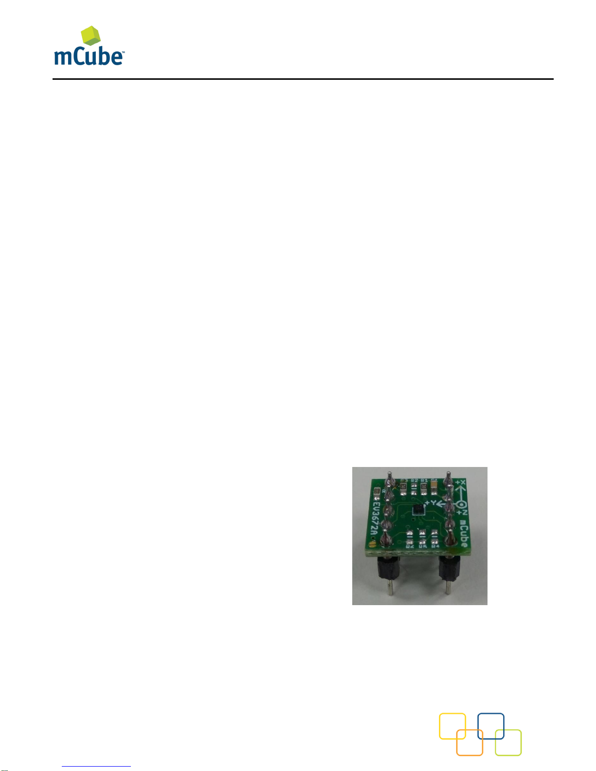
The EVA3672A is a prebuilt circuit board
with MC3672 WLCSP 3-axes sensor. The
MC3672 has internal sample rate from 14 to
1300 samples / second and measures
acceleration with a wide usage range, from
+/-2g up to +/-16g, and 6-bit to 14-bit high
precision ADC output, which is easy to fit
on top of the microcontroller, such as an
Arduino. The accelerometer communicates
via I2C and gives out motion detection or
sample acquisition conditions to trigger an
interrupt toward a MCU.
The sensor data is easily readable by
connecting DVDD to 3.3V, GND to ground,
and SCL/SDA pins to your Arduino I2C
clock and data pin respectively. Download
the MC3672 library from GitHub onto the
board, run the example sketch, and then
sensor data shortly comes out in raw data
count and SI unit accelerometer
measurements. An easy-to-use
demonstration on EVA3672A using the
Arduino platform is included in this
document.
MC3672 FEATURES
Range, Sampling & Power
• ±2,4,8,12 or 16g ranges
• 8, 10 or 12-bit resolution with FIFO
o 14-bit single samples
• Sample rate 14 - 1300 samples/sec
• Sample trigger via internal oscillator,
clock pin or software command
• Sniff and Wake modes
• 0.4 μA Sniff current @ 6Hz
• Separate or combined sniff/wake
• Ultra-Low Power with 32 sample
FIFO
o 0.9 μA typical current @ 25Hz
o 1.6 μA typical current @ 50Hz
o 2.8 μA typical current @ 100Hz
o 36 μA typical current @ 1300Hz
Simple System Integration
• I2C interface, up to 1 MHz
• SPI Interface, up to 8 MHz
• 1.29 × 1.09 × 0.742 mm 8-pin
WLCSP package
• Single-chip 3D silicon MEMS
• Low noise to 2.3mg RMS
Page 2

MC3672 Accelerometer Driver Quick Start Guide and Demo
mCube Proprietary. APS-045-0017v1.2 2 / 19
© 2018 mCube Inc. All rights reserved.
TABLE OF CONTENTS
1 General Operation ........................................................................................................... 3
2 Assembly and Test .......................................................................................................... 6
3 Demo ............................................................................................................................... 8
4 Library Reference .......................................................................................................... 11
5 Downloads ..................................................................................................................... 15
6 Schematics .................................................................................................................... 16
7 Fabrication print ............................................................................................................. 17
8 Revision History ............................................................................................................. 18
9 Legal .............................................................................................................................. 19
Page 3
MC3672 Accelerometer Driver Quick Start Guide and Demo
mCube Proprietary. APS-045-0017v1.2 3 / 19
© 2018 mCube Inc. All rights reserved.
1 GENERAL OPERATION
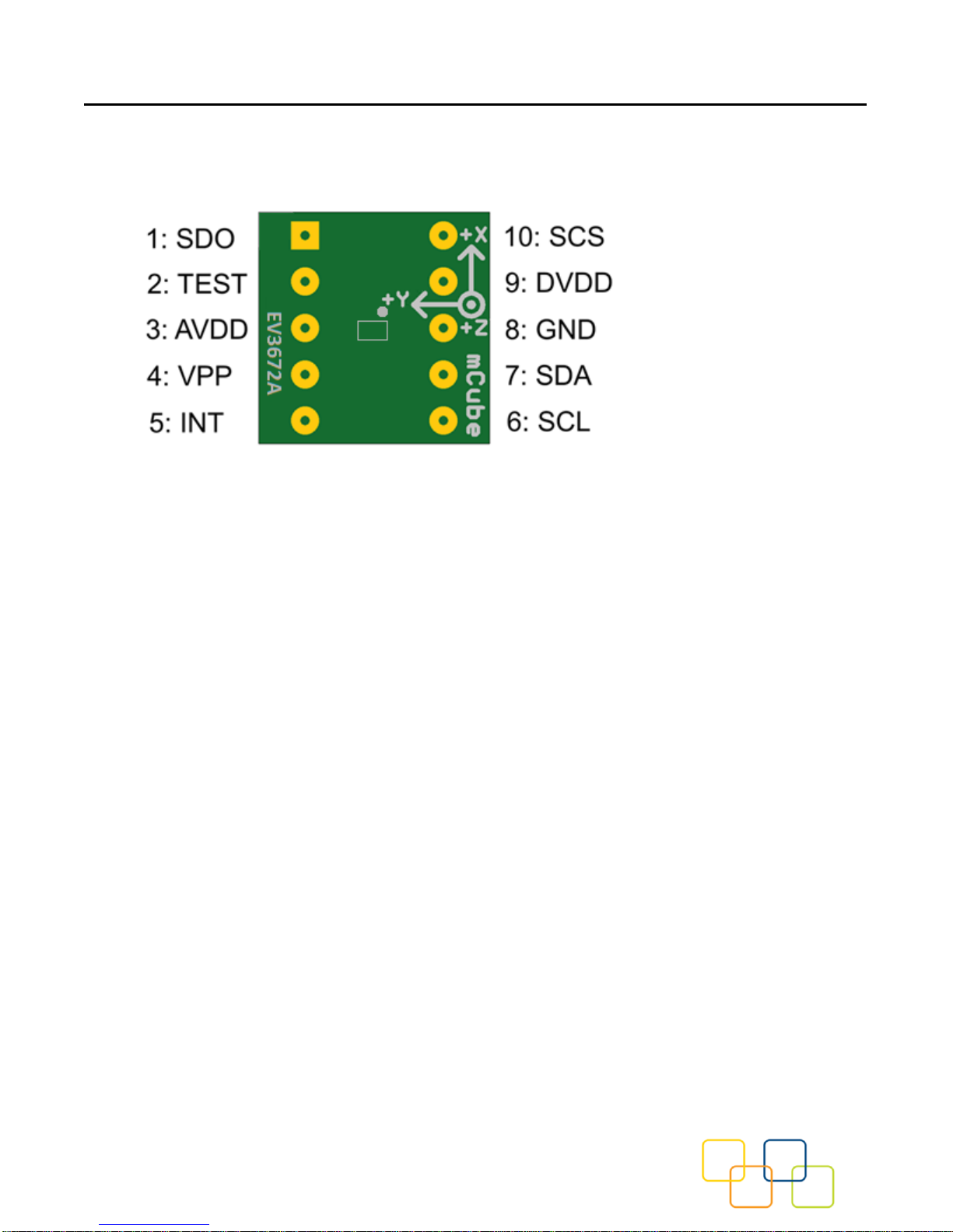
1.1 PINOUTS
1.2 POWER PINS
DVDD – 3.3V Power Supply Input
GND – Ground Pin for Power and Logic
1.3 I2C PINS
Connect the SCL (I2C clock pin) to your microcontroller’s I2C clock line. This pin can be
used with 3V logic. A 4.7K pull-up resistor is required for this pin. Simply, add a 4.7K pullup resistor on R4 to make the I2C clock signal works normally.
Connect the SDA (I2C data pin) to your microcontroller’s I2C data line. This pin can be
used with 3V logic. A 4.7K pull-up resistor is required for this pin. Simply, add a 4.7K pullup resistor on R5 to ensure functionality of the I2C data signal.
Page 4
MC3672 Accelerometer Driver Quick Start Guide and Demo
mCube Proprietary. APS-045-0017v1.2 4 / 19
© 2018 mCube Inc. All rights reserved.
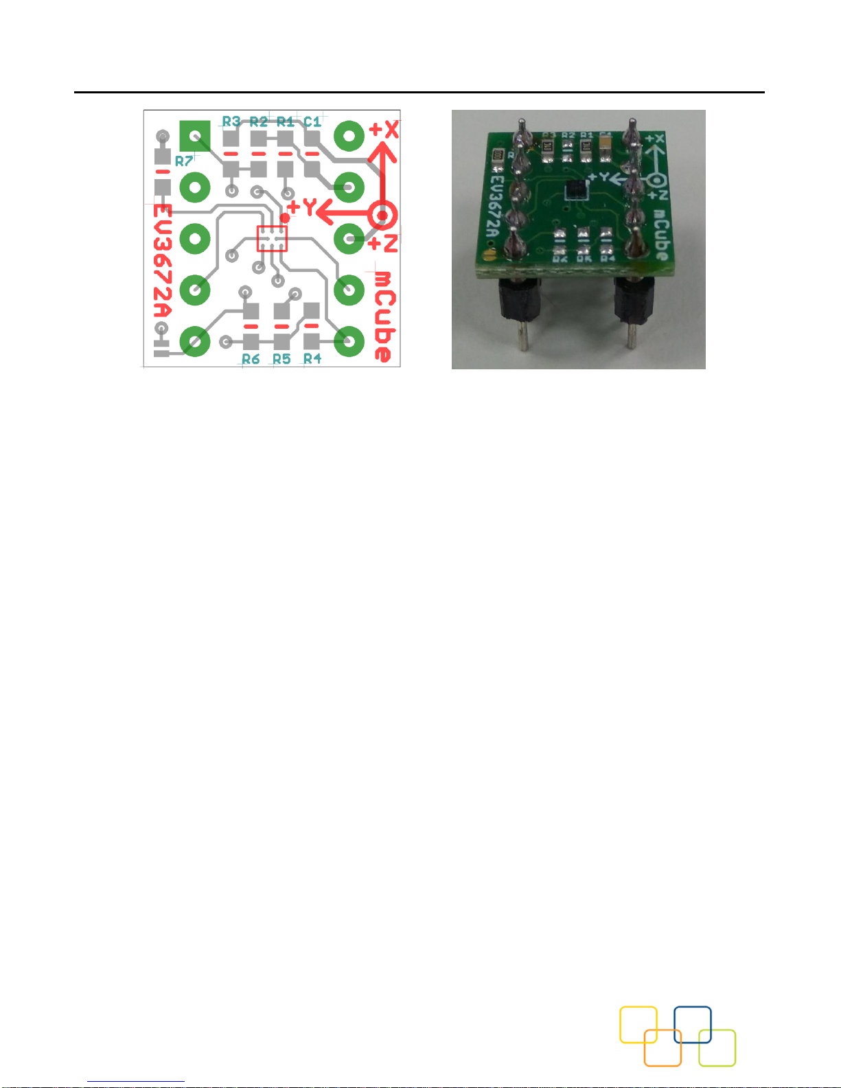
R4, R5: If using I2C and I2C pull-up resistors are needed for your application then
install~4.7KΩ resistors into R4 (SCL clock pin) and R5 (SDA data pin) which are not
installed by factory default. In addition, besides soldering resisters on R4/R5, you can add
axial lead 4.7K ohm resistors to the SDA and SCL pin respectively. It will work the same
either way.
NOTE: DO NOT install more than one setup pull-up resistors per I2C bus.
1.4 SPI PINS
With an SPI connection, there is always one master device (usually a microcontroller)
which controls the peripheral devices. Typically, there are three wires commonly
connected to all the devices:
Connect the SCS (Slave Select) to the pin on the device that the master can use to enable
and disable SPI cycles.
Connect the SCL (Serial clock) to the pin where the clock pulses synchronize data
transmission generated by the master
Connect SDO to the pin where the Slave sends data to the master (Master Input, Slave
Output).
Connect SDA to the pin where the Master sends data to the peripherals (Master Output,
Slave Input).
Page 5

MC3672 Accelerometer Driver Quick Start Guide and Demo
mCube Proprietary. APS-045-0017v1.2 5 / 19
© 2018 mCube Inc. All rights reserved.
1.5 INTERRUPT PINS
INT - HW interrupt signal pin. This pin will be triggered by the device when data is ready
to read, or a motion event is detected by the accelerometer. (Not currently supported in
the library for the interrupt pin, so please check the datasheet for the I2C commands and
related registers).
Page 6
MC3672 Accelerometer Driver Quick Start Guide and Demo
mCube Proprietary. APS-045-0017v1.2 6 / 19
© 2018 mCube Inc. All rights reserved.
2 ASSEMBLY AND TEST
Please note that the SPI and I2C interfaces cannot both be active at the same time as
the clock (SCK) and data (SDA) are shared between the two protocols.
2.1 I2C INTERFACE
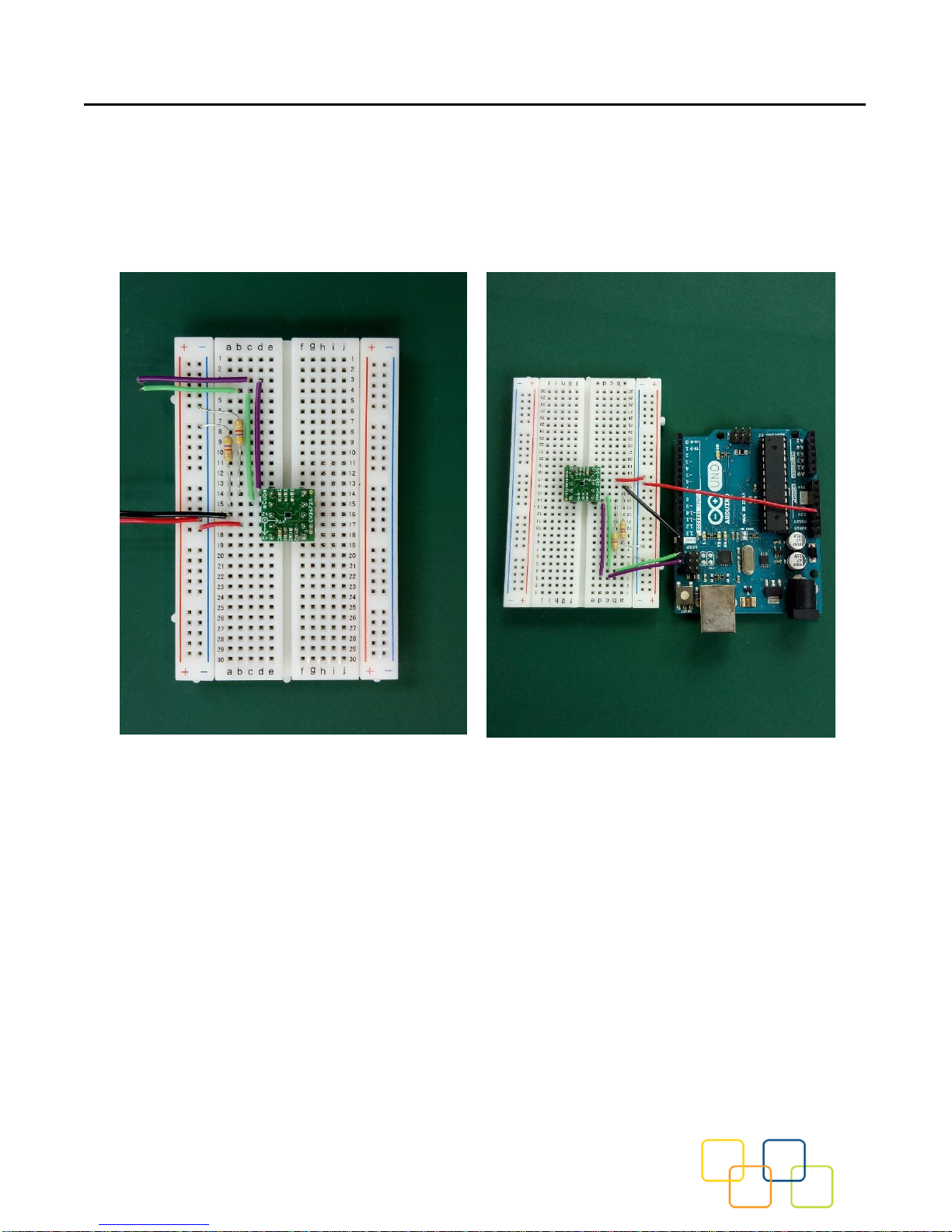
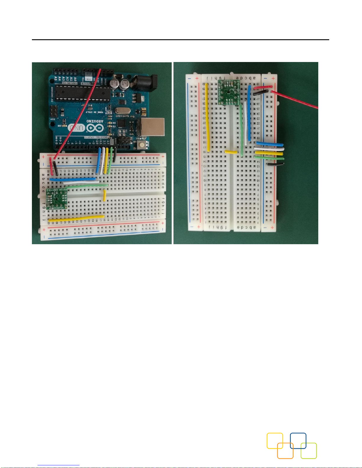
The EV3672A evaluation board can be easily wired to any microcontroller. This example
shows a typical Arduino UNO platform. For other microcontrollers, be sure it has I2C with
repeated-start support, then port the code. Please refer to the illustration below to connect the
related pins.
• Connect DVDD to the power supply, 3.3V. (Providing higher voltage, like 5V may
damage the sensor).
• Connect GND to common power/data ground.
• Connect the SCL pin to the I2C clock SCL pin on your Arduino.
• Connect the SDA pin to the I2C data SDA pin on your Arduino.
The MC3672 has a default I2C address of 0x4C and it can be changed to 0x6C by tying
the DOUT pin to VDD.
Page 7
MC3672 Accelerometer Driver Quick Start Guide and Demo
mCube Proprietary. APS-045-0017v1.2 7 / 19
© 2018 mCube Inc. All rights reserved.
2.2 SPI INTERFACE
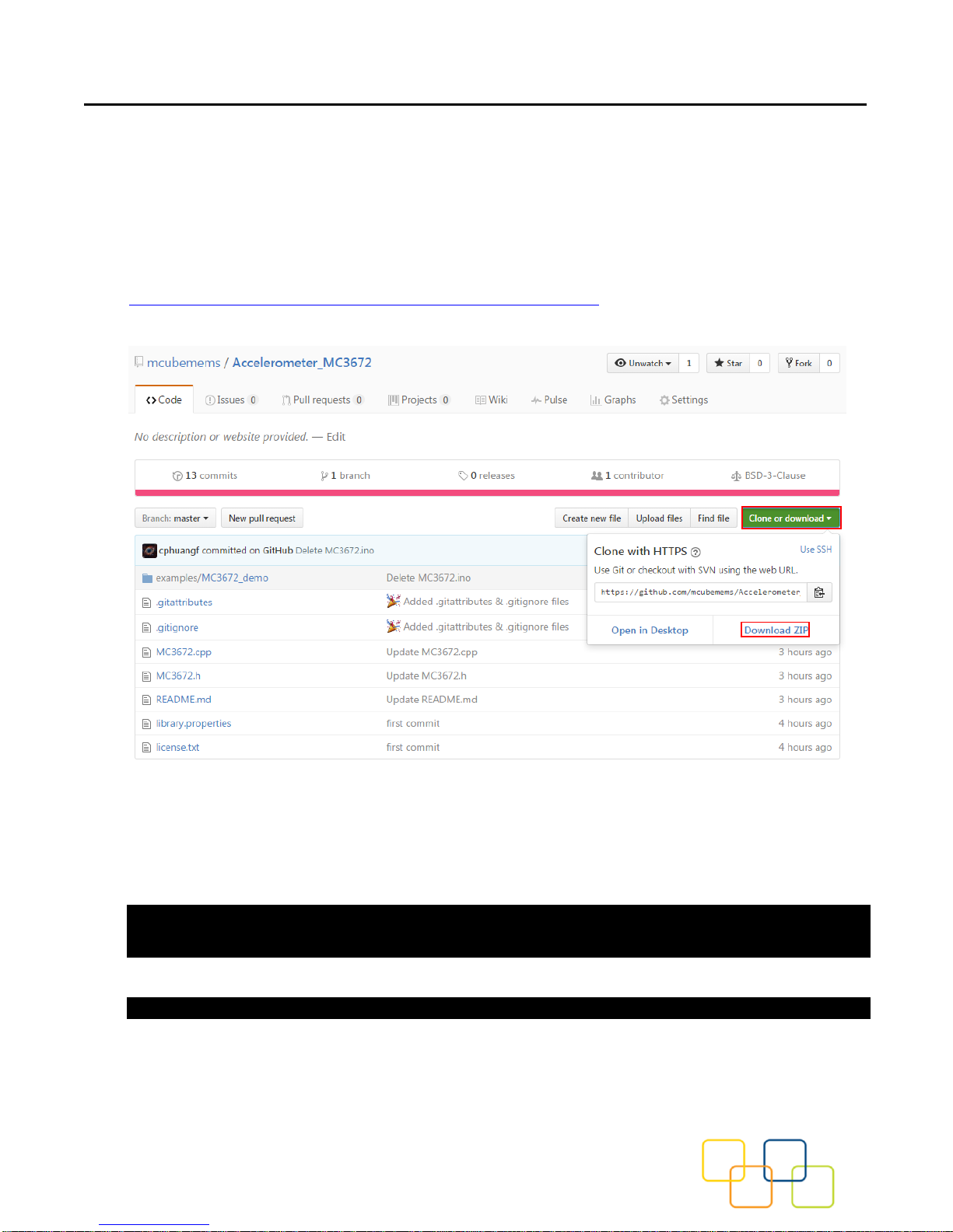
The EV3672A evaluation board can be easily wired to any microcontroller. This example
shows a typical Arduino UNO platform. Please refer to the illustration below for connecting the
related pins and then port the code to get the raw X, Y, Z sensor data.
• Connect DVDD to the power supply, 3.3V. (Providing higher voltage, like 5V may
damage the sensor.)
• Connect GND to common power/data ground.
• Connect SCL to digital I/O pin 13 as Serial Clock.
• Connect SDO to digital I/O pin 12 as Master Input, Slave Output.
• Connect SDA to digital I/O pin 11 as Master Output, Slave Input.
• Connect SCS to digital I/O pin 10 as Slave Select.
Page 8
MC3672 Accelerometer Driver Quick Start Guide and Demo
mCube Proprietary. APS-045-0017v1.2 8 / 19
© 2018 mCube Inc. All rights reserved.
3 DEMO
3.1 DOWNLOAD THE DRIVER FROM GITHUB
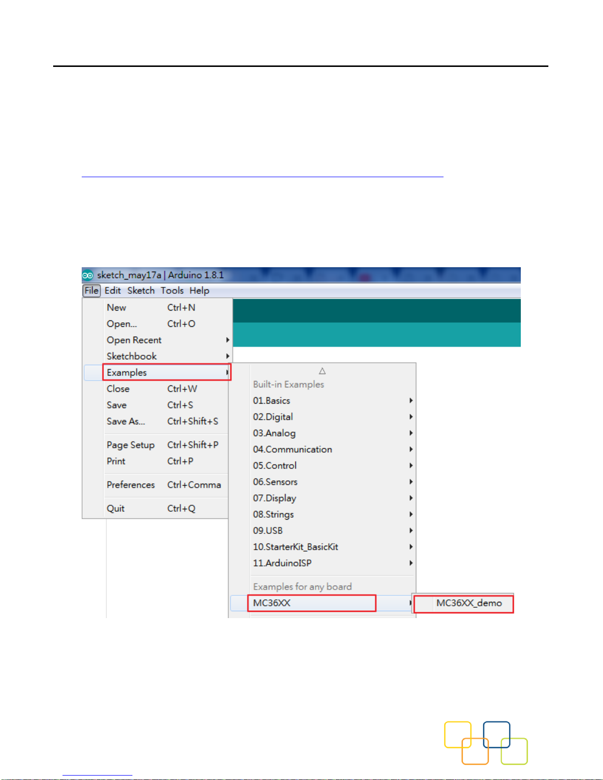
To begin reading sensor data, you will need to download the MC3672 Library from the
GitHub repository. Do this by visiting the GitHub repository and manually downloading or
simply click this button the attached URL to download the zip file.
https://github.com/mcubemems/Accelerometer_MC36XX
Rename the uncompressed folder Accelerometer_MC36XX and check that the
Accelerometer_MC36XX folder consisting of MC36XX.cpp and MC36XX.h
If you need the sensor running on SPI, please configure the bus as SPI in the
MC36XX.h shown as below. Otherwise, the default is I2C bus.
//#define MC36XX_CFG_BUS_I2C
#define MC36XX_CFG_BUS_SPI
SPI could support 8MHz speed if high speed mode is enabled as below.
#define SPI_HS
Page 9
MC3672 Accelerometer Driver Quick Start Guide and Demo
mCube Proprietary. APS-045-0017v1.2 9 / 19
© 2018 mCube Inc. All rights reserved.
Place the Accelerometer_MC3672 library folder to your
Arduino_sketch_folder/libraries/ folder.
You may need to create the library subfolder if it is your first library files. Then just restart
the IDE.
An excellent tutorial on Arduino library installation is located at:
http://learn.adafruit.com/adafruit-all-about-arduino-libraries-install-use
3.2 LOAD THE DEMO
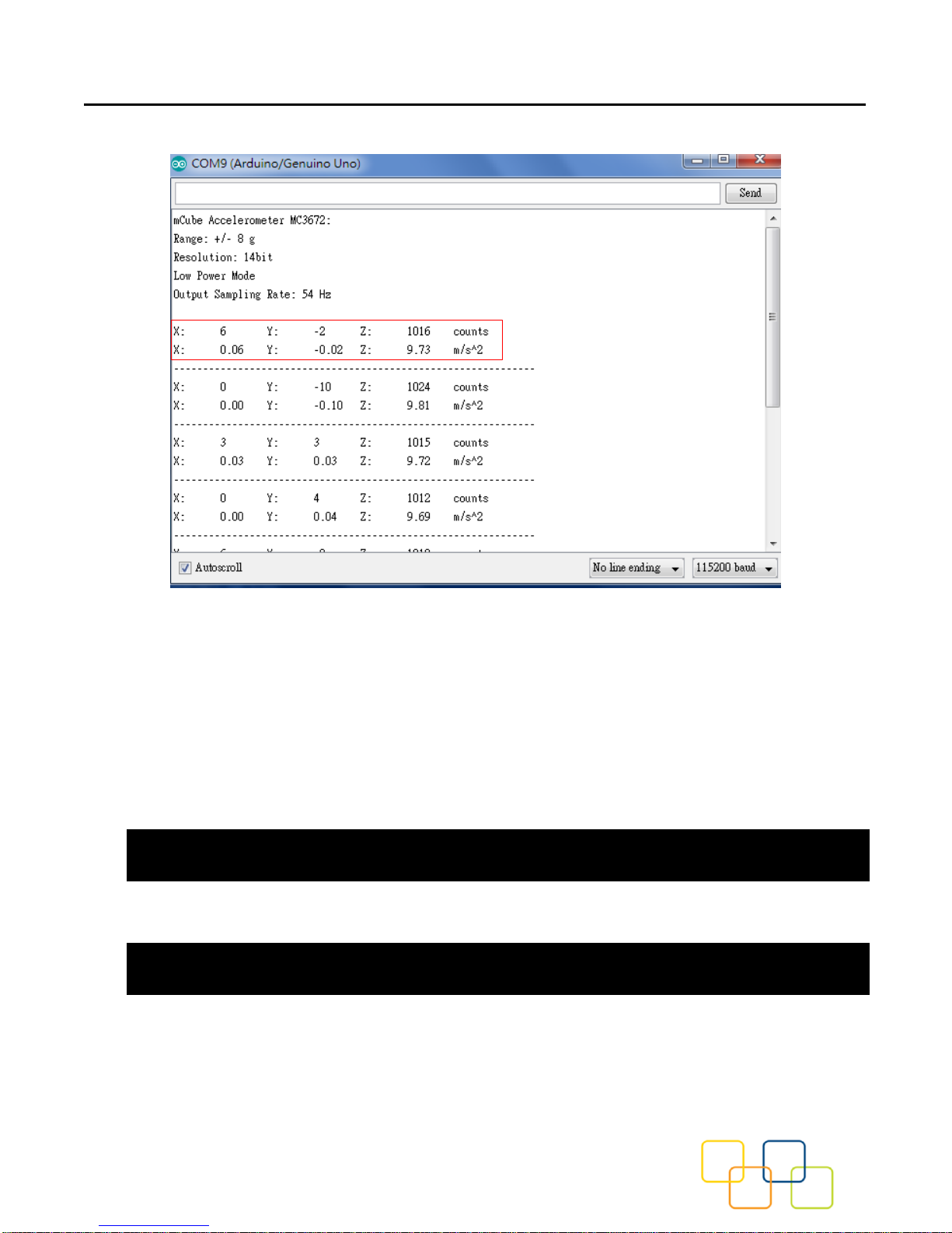
Open File->Examples->MC3672-> MC3672demo and upload to your Arduino while it is wired
to the sensor.
Page 10
MC3672 Accelerometer Driver Quick Start Guide and Demo
mCube Proprietary. APS-045-0017v1.2 10 / 19
© 2018 mCube Inc. All rights reserved.
Now open the serial terminal window at 115,200 baud rate speed to begin the test.
You will see the output from the serial terminal showing the current range scale and resolution
of the sensor in the first three lines followed by two lines of output sensor data at some output
data rate which depict “raw count" data for line 1: X: 6 Y: -2 Z: 1016 with 8G range, 14bit ADC
resolution. Line 2 indicates the SI units for measuring acceleration as X: 0.06 m/s^2 Y: -0.02
m/s^2 Z: 9.73 m/s^2.
This demo also includes the example for FIFO and Sniff interrupt mode. Those could be
enable by modify the definition below. These two examples must be run separately.
#define ENABLE_FIFO_WAKEUP 1
#define ENABLE_SNIFF_SHAKE_WAKEUP 0
Default input pin for interrupt is pin 8 and default FIFO threshold is 3 samples. FIFO size could
be set to maximum 32 samples or just enable FIFO to FIFO_FULL mode.
#define INTERRUPT_PIN 8
#define FIFO_SIZE 3
Page 11

MC3672 Accelerometer Driver Quick Start Guide and Demo
mCube Proprietary. APS-045-0017v1.2 11 / 19
© 2018 mCube Inc. All rights reserved.
4 LIBRARY REFERENCE
4.1 CREATE MCUBE_MC36XX OBJECT
You can create the MCUBE_MC36XX object with:
MC36XX MC36XX_acc = MC36XX();
4.2 INITIALIZE AND CONFIGURE SENSOR
Initialize and configure the sensor with:
MC36XX_acc.start();
Wake up sensor with your own configuration, it will follow the factory default setting:
MC36XX_acc.wake();
Stop sensor to change setting:
MC36XX_acc.stop();
Set sensor as sniff mode:
MC36XX_acc.sniff ();
4.3 SET RANGE
Set the accelerometer max range to ±2g, ±4g, ±8g or ±16g with:
MC36XX_acc.SetRangeCtrl(MC36XX_RANGE_8G);
4.4 READ RANGE
Read the current range with:
MC36XX_acc.GetRangeCtrl();
It returns: 0 for ±2g, | 1 for ±4g, | 2 for ±8g | 3 for ±16g.
Page 12

MC3672 Accelerometer Driver Quick Start Guide and Demo
mCube Proprietary. APS-045-0017v1.2 12 / 19
© 2018 mCube Inc. All rights reserved.
4.5 SET RESOLUTION
Set the accelerometer resolution to 6, 7, 8, 10, 12 or 14 bit.
MC36XX_acc.SetResolutionCtrl(MC36XX_RESOLUTION_14BIT);
When the FIFO is enabled, the output of the FIFO is mapped to registers 0x02 to 0x07,
and the data has a maximum resolution of 12-bits.
4.6 READ RESOLUTION
Read the current resolution with:
MC36XX_acc.GetResolutionCtrl();
It returns: 0 for 6-bit | 1 for 7-bit | 2 for 8-bit | 3 for 10-bit | 4 for 12-bit | 5 for 14-bit.
4.7 SET CWAKE SAMPLING RATE
Set the accelerometer cwake mode sampling rate with:
MC36XX_acc.SetCWakeSampleRate (MC36XX_CWAKE_SR_DEFAULT_54Hz);
4.8 READ CWAKE SAMPLING RATE
Read the current cwake sampling rate with:
MC36XX_acc.GetCWakeSampleRate ();
It returns sampling rate from 14 ~ 600 Hz.
4.9 SET SNIFF SAMPLING RATE
Set the accelerometer sniff mode sampling rate with:
MC36XX_acc.SetSniffSampleRate (MC36XX_SNIFF_SR_DEFAULT_7Hz);
Page 13

MC3672 Accelerometer Driver Quick Start Guide and Demo
mCube Proprietary. APS-045-0017v1.2 13 / 19
© 2018 mCube Inc. All rights reserved.
4.10 READ SNIFF SAMPLING RATE
Read the current sniff sampling rate with:
MC36XX_acc.GetSniffSampleRate ();
This returns sampling rate from 7 ~ 600 Hz.
4.11 CONFIG SNIFF MODE
Set the threshold values used by the SNIFF logic for activity detection:
MC36XX_acc.SetSniffThreshold (MC36XX_AXIS_X,5);
All three axes could be configured separately with different threshold value.
Set the threshold values used by the SNIFF logic for activity detection:
MC36XX_acc.SetSniffDetectCount (MC36XX_AXIS_X,3);
For each axis, a delta count is generated and compared to the threshold. When the delta
count is greater than the threshold, a SNIFF wakeup event occurs. There is a unique sniff
threshold for each axis, and an optional “false detection count” which requires multiple
sniff detection events to occur before a wakeup condition is declared.
Configure sniff and/or mode with:
MC36XX_acc.SetSniffAndOrN(MC36XX_ANDORN_OR);
The SNIFF block supports the logical AND or OR of the X/Y/Z SNIFF wakeup flags when
generating a SNIFF wakeup interrupt.
Configure sniff delta mode with:
MC36XX_acc.SetSniffDeltaMode(MC36XX_DELTA_MODE_C2P);
Page 14

MC3672 Accelerometer Driver Quick Start Guide and Demo
mCube Proprietary. APS-045-0017v1.2 14 / 19
© 2018 mCube Inc. All rights reserved.
C2P mode: The current sample and the immediate previous sample are subtracted
generate a delta
C2B mode: The current sample and the first sample captured when entering SNIFF mode
are subtracted to generate a delta.
4.12 CONFIG INTERRUPT MODE
Configure the interrupt mode with:
MC36XX_acc.SetINTCtrl(0,0,0,0,1);
MC36XX have 5 interrupt modes – FIFO_THR | FIFO FULL | FIFO EMPTY | ACQ | WAKE.
These modes can only be enabled separately.
4.13 READ RAW COUNT DATA
Read the raw count data and SI unit measurement with:
MC36XX_acc.readRawAccel();
Page 15

MC3672 Accelerometer Driver Quick Start Guide and Demo
mCube Proprietary. APS-045-0017v1.2 15 / 19
© 2018 mCube Inc. All rights reserved.
5 DOWNLOADS
5.1 MC3630 ACCELEROMETER DATASHEET
http://www.mcubemems.com/product/mc3630-3-axis-accelerometer/
5.2 MC3635 ACCELEROMETER DATASHEET
http://www.mcubemems.com/product/mc3635-3-axis-accelerometer/
5.3 MC3672 ACCELEROMETER DATASHEET
http://www.mcubemems.com/product/mc3672-3-axis-accelerometer/
5.4 MC36XX DRIVER AT GITHUB
https://github.com/mcubemems/Accelerometer_MC36XX
5.5 ALL OTHER MCUBE DOCUMENTATION
http://www.mcubemems.com/resources-support/resources/
Page 16
MC3672 Accelerometer Driver Quick Start Guide and Demo
mCube Proprietary. APS-045-0017v1.2 16 / 19
© 2018 mCube Inc. All rights reserved.
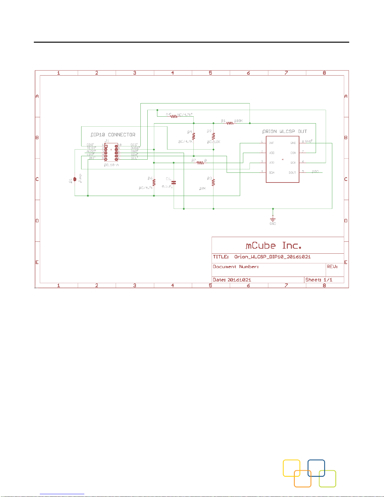
6 SCHEMATICS
Page 17

MC3672 Accelerometer Driver Quick Start Guide and Demo
mCube Proprietary. APS-045-0017v1.2 17 / 19
© 2018 mCube Inc. All rights reserved.
7 FABRICATION PRINT
Page 18

MC3672 Accelerometer Driver Quick Start Guide and Demo
mCube Proprietary. APS-045-0017v1.2 18 / 19
© 2018 mCube Inc. All rights reserved.
8 REVISION HISTORY
Date
Revision
Description
2016-12-08
APS-045-0017v1.0
First release.
2017-02-06
APS-045-0017v1.1
Added SPI mode interface.
2018-05-10
APS-045-0017v1.2
Added example codes for high speed SPI mode, FIFO mode, and Sniff mode.
Page 19

MC3672 Accelerometer Driver Quick Start Guide and Demo
mCube Proprietary. APS-045-0017v1.2 19 / 19
© 2018 mCube Inc. All rights reserved.
9 LEGAL
1. M-CUBE reserves the right to make corrections, modifications, enhancements, improvements and other
changes to its products and to this document at any time and discontinue any product without notice. The
information contained in this document has been carefully checked and is believed to be accurate. However, MCUBE shall assume no responsibilities for inaccuracies and make no commitment to update or to keep current
the information contained in this document.
2. M-CUBE products are designed only for commercial and normal industrial applications and are not suitable
for other purposes, such as: medical life support equipment; nuclear facilities; critical care equipment; military /
aerospace; automotive; security or any other applications, the failure of which could lead to death, personal injury
or environmental or property damage. Use of the products in unsuitable applications are at the customer’s own
risk and expense.
3. M-CUBE shall assume no liability for incidental, consequential or special damages or injury that may result
from misapplication or improper use of operation of the product.
4. No license, express or implied, by estoppel or otherwise, to any intellectual property rights of M-CUBE or any
third party is granted under this document.
5. M-CUBE makes no warranty or representation of non-infringement of intellectual property rights of any third
party with respect to the products. M-CUBE specifically excludes any liability to the customers or any third party
regarding infringement of any intellectual property rights, including the patent, copyright, trademark or trade secret
rights of any third party, relating to any combination, machine, or process in which the M-CUBE products are
used.
6. Examples of use described herein are provided solely to guide use of M-CUBE products and merely indicate
targeted characteristics, performance and applications of products. M-CUBE shall assume no responsibility for
any intellectual property claims or other problems that may result from applications based on the examples
described herein
7. Information described in this document including parameters, application circuits and its constants and
calculation formulas, programs and control procedures are provided for the purpose of explaining typical
operation and usage. “Typical” parameters that may be provided in M-CUBE data sheets and/or specifications
can and do vary in different applications and actual performance may vary over time. All operating parameters
including “Typical,” must be validated for each customer application by customer’s technical experts. In no event
shall the information described be regarded as a guarantee of conditions or characteristics of the products.
Therefore, the customer should evaluate the design sufficiently as whole system under the consideration of
various external or environmental conditions and determine their application at the customer’s own risk. M-CUBE
shall assume no responsibility or liability for claims, damages, costs and expenses caused by the customer or any
third party, owing to the use of the above information.
is a trademark of M-CUBE, Inc.
M-CUBE and the M-CUBE logo are trademarks of M-CUBE, Inc.,
All other product or service names are the property of their respective owners.
© M-CUBE, Inc. 2018. All rights reserved.
 Loading...