

MC-LR/MC-LR-4
MC-LRS/MC-LRS-4
User Manual/Web Interface
Router Description
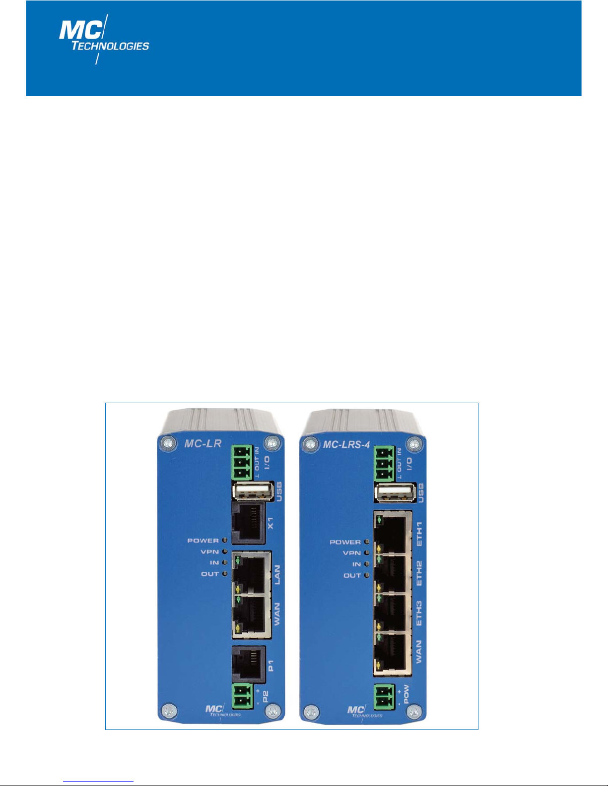
MC Technologies routers are designed for industrial use.
Advantages at a glance:
• Easy expansion of protected networks.
• High-security data transfer via IPsec or OpenVPN tunnel, plus integrated firewall.
• Easy and identical configuration of router family via integrated web server, USB stick
or "remote".
• Event alerts by email.
• Top-hat rail mounting.
• Use of applications with RS232 or RS485 interfaces on demand
(only 2 port variantes).
• Integrated logbook records device-specific events.
• Delivered ready-to-use, including power supply plug and Ethernet connecting cable.
All specifications for the 2-port version also apply for the 4-port version.
2
MC Technologies GmbH

User Manual/Web Interface MC-LR/MC-LR-4/MC-LRS/MC-LRS-4 – 01/2018 (FW 2.07.3)
3
Contents
1. Configuration via the integrated web interface 4
1.1 Preparations 4
1.2 Configuration 1.2.1 Configuration via web interface 4
1.2.2 Local IP address is not (longer) known - configuration button 4
1.2.3 Resetting all parameters 4
1.3 Status 1.3.1 Network Connections 5
1.3.2 I/O Status 6
1.3.3 ComSERVER (Only for MC Router with RS232 or RS485 interface on X1) 6
1.3.4 Routing Table 6
1.3.5 DHCP Leases 7
1.4 Local Network 1.4.1 IP Configuration 7
(Lokales Netzwerk) 1.4.2 DHCP Server 8
1.4.3 Local Static Routes 9
1.5 Wide Area Network 1.5.1 WAN Setup 10
1.5.1.1 Static Address- Preferred setting for operation
in local networks 10
1.5.1.2 DHCP Client- Preferred setting for operation
with cable modems 11
1.5.1.3 PPPoE- Preferred setting for operation
with DSL modems 11-12
1.5.2 Static Routes 12
1.5.3 DynDNS 13
1.5.4 Connection Check 14
1.6 Networtk Security 1.6.1 General Setup 15
(Netzwerksicherheit) 1.6.2 Firewall 16
1.6.3 NAT Table (Port forwarding) 17
1.7 VPN 1.7.1 IPsec 1.7.1.1 Connections 18-21
1.7.1.2 Certificates 22
1.7.1.3 Status 22
1.7.2 OpenVPN 1.7.2.1 Connections (Tunnel 1 and 2 / Clients) 23-25
1.7.2.2 Connections Server (only MC-LR Server) 26-29
1.7.2.3 Port Forwarding 29
1.7.2.4 Certificates 30
1.7.2.5 Static Keys (Preshared Key) 30
1.7.2.6 Status 31
1.8 I/O 1.8.1 Inputs 32
1.8.2 Outputs 32-33
1.8.3 Socket Server 33
1.9 System 1.9.1 Hardware 34
1.9.2 Software 35
1.9.3 System Configuration 35-38
1.9.4 User 39
1.9.5 Log-File 39
1.9.6 ComSERVER (Only for MC Router with RS232 or RS485 interface on X1) 40
1.9.7 SMTP Configuration - sending emails 40-41
1.9.8 Configuration Up-/Download 41
1.9.9 RTC - Setting the time and date / Time Server 42
1.9.10 Reboot - restarting the router 43
1.9.11 Firmware Update 43
2. Additional functions 2.1 Router configuration using SSH and XML file 44
2.1.1 Download configuration via SSH 44
2.1.2 Upload configuration via SSH 44
2.2 Sending and receiving IO status, email and router status using XML
files via the router socket server 45
2.2.1 Sample XML files 45
2.2.2 Functions test using Windows HyperTerminal 46

MC Technologies GmbH
4
1. Configuration via the integrated web interface
1.1 Preparations
1. Hook the router up to the power supply using connection
"P1
",
"P2v or
"POW
".
2. To configure, connect the PC and the router to Ethernet port “ETH1“ using an Ethernet cable.
3. For configuration, you will need a browser (i.e. Mozilla Firefox, Microsoft Internet Explorer, etc.) on a PC.
The router must be connected to the power supply. The PC to be used for configuration must be connected to an
Ethernet port on the router.
1.2 Configuration
1.2.1 Configuration via web interface
1. The PC must be set to
"obtain IP address automatically".
This is the default setting for PCs.
2. Open a browser on the PC.
3. Type the IP address (default: 192.168.0.1) in the address field.
4. For authentication purposes a user name and password must be entered. The default settings for the user name
and password are both "admin", which should be entered in the corresponding fields. For your security, the
password setting can be changed at any time using the "System/User" menu item on the web interface
(see Page 39).
1.2.2 Local IP address is not (longer) known – configuration button
The router is set to "Web access reset" unless you change the default setting. Press the configuration button for at
least 5 seconds using a pointed object. The router web interface can be temporarily readdressed using the default IP
address (192.168.0.1) for the Ethernet (LAN) connection. The configuration settings will not be lost when doing so.
Web access reset
Important note! The router does not supply any IP address to the connected PC via DHCP. You must thus
assign a fixed IP address to the PC (e.g. 192.168.0.2, default gateway 192.168.0.1).
You will now have access to web management using the default access data. Please check the settings for the router IP
address, user name and password and make any changes required.
Factory reset
You changed the setting to "Factory reset" (see Item 1.9.3 "System Configuration/Reset button"). Press the configuration button for at least 5 seconds using a pointed object. The router web interface can be readdressed using the
default IP address (192.168.0.1) for the Ethernet (LAN) connection.
1.2.3 Resetting all parameters on the web interface
Resetting of all router settings to the factory default mode can be carried out via the internal web interface. Please click
on the
"Applyv button for the
"Reset to Factory Defaults"
function in the
"System/Configuration Up-/Download
"
sub-
menu.
To reconfigure the router using the default IP address you will need to use the configuration button on the rear side of
the device. This function depends on the setting you defined in Section 1.9.3
"Reset button".
Important note! All configuration settings will be deleted and reset to the „Factory Defaults“ setting.

User Manual/Web Interface MC-LR/MC-LR-4/MC-LRS/MC-LRS-4 – 01/2018 (FW 2.07.3)
5
Status information on mobile connection and on local Ethernet network.
1.3.1 Network Connections
1.3 Status
Network Connections
Wireless Network
Link
VPN connected: Active VPN connection via the network.
Not connected: No packet data connection in the network.
IP Address Allocated IP address from the network.
Netmask Allocated net mask from the network.
DNS Server IP address of the DNS server.
Sec. DNS Server IP address of the alternate DNS server.
RX bytes Sum of received data since last login.
TX bytes Sum of sent data since last login.
Local Network
Link For each LAN-Port Link (1-4 depending of the router type) the connection of the port is shown
Connected: The local Ethernet is active.
Not connected: The local Ethernet is not active.
IP Address Router IP address in the local network.
Netmask Router net mask in the local network.
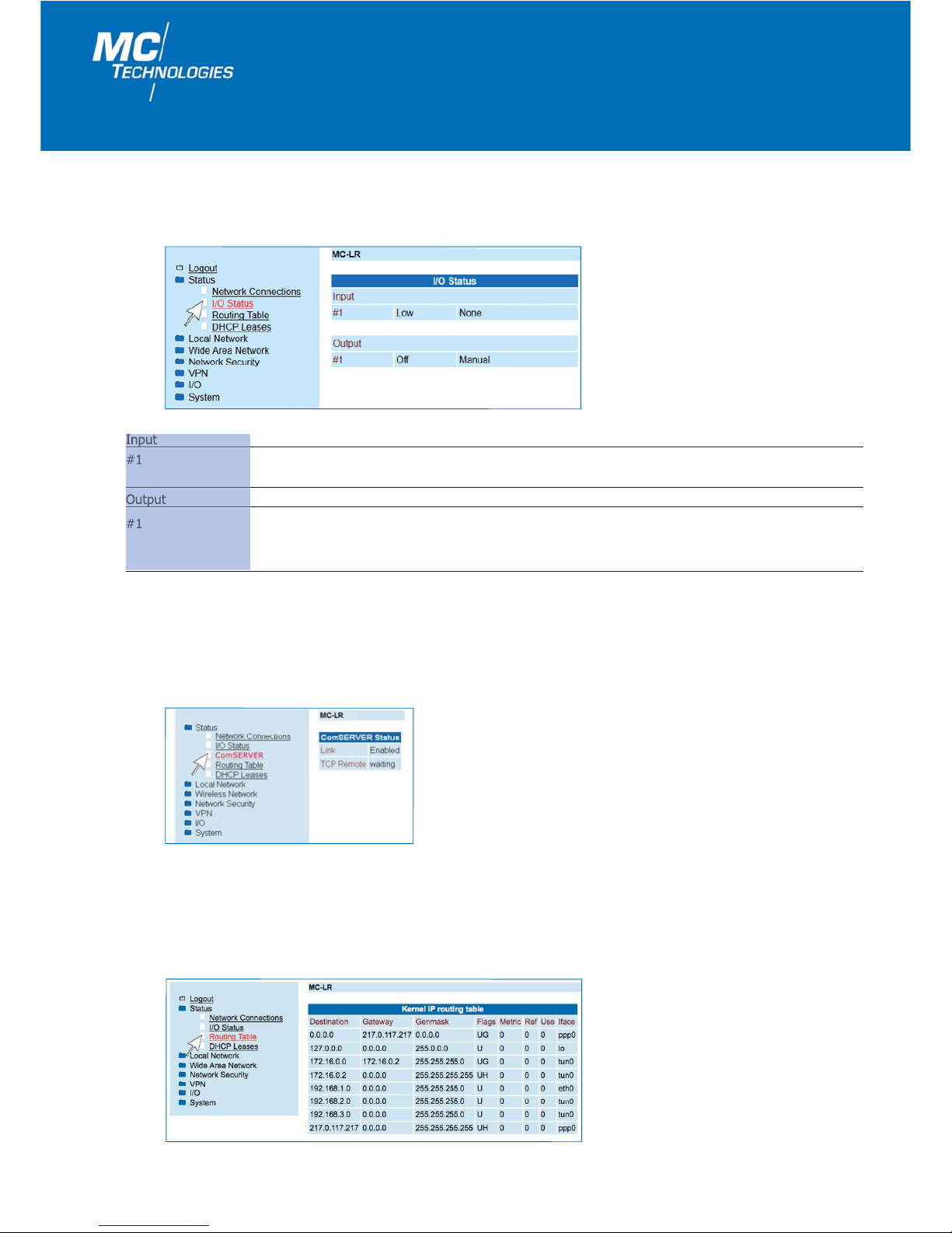
1.3.2 I/O Status
1.3.4 Routing Table
6
MC Technologies GmbH
Status information of I/O interfaces IN and OUT.
Input Signal Event
#1
Low: The signal is low. None: No event has been triggered.
High: The signal is high. E-Mail: An email is being sent.
Output Signal Event
#1
ON: Output active. Based on: Manual ON, Remote Controlled ON,
VPN Service ON, Internet Link ON or Connection lost ON.
Off: Output is not active.
Display of current routing table.
Status display of integrated ComSERVER
1.3.3 ComSERVER (only for MC Router with RS232 or RS485 interface on X1)
See also 1.9.6. ComSERVER
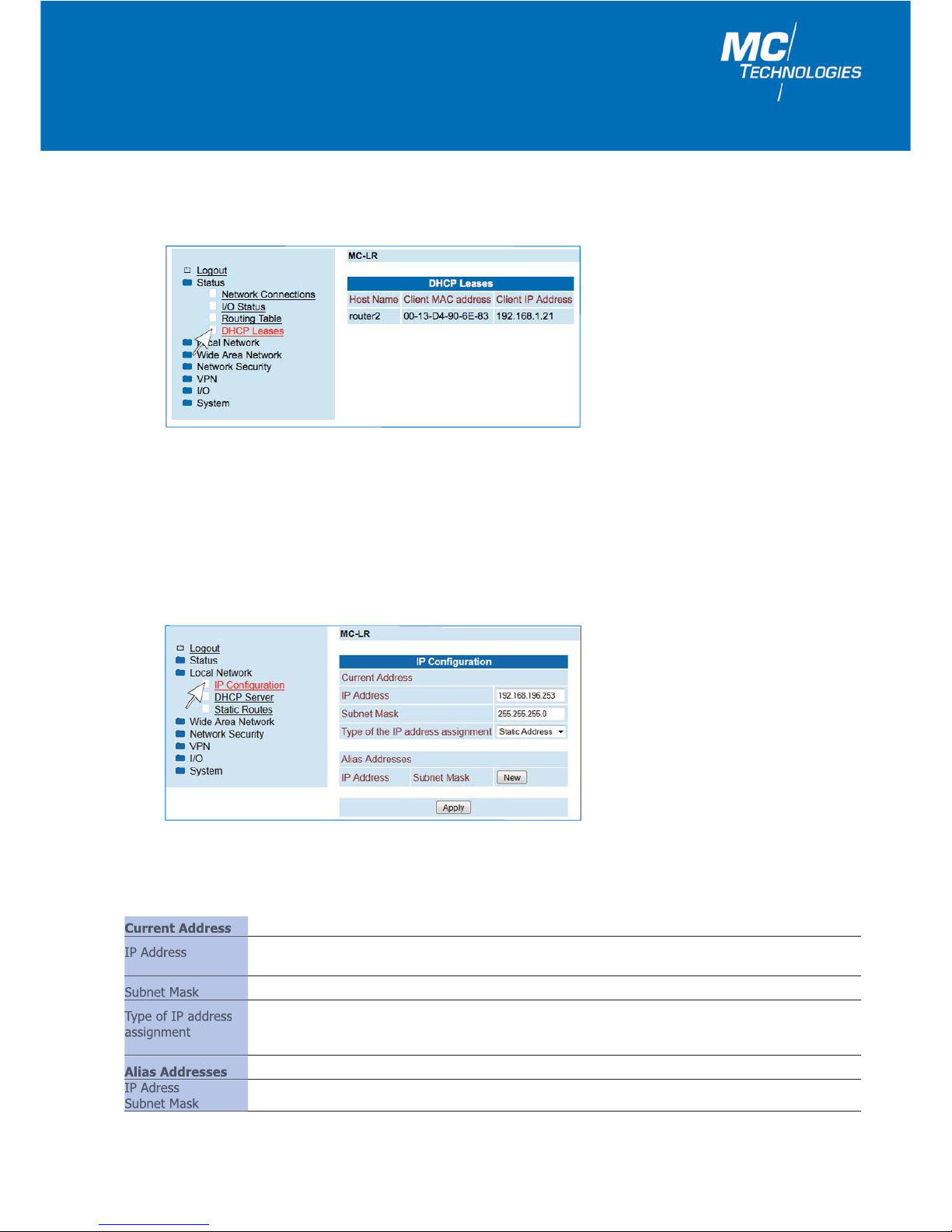
1.4 Local Network
Setup of local IP address and subnet mask for router. Set your parameters and click "Apply". Your parameters have
been saved but not yet applied. To apply the setup, restart the router.
1.4.1 IP Configuration
Display allocation of MAC address to IP address of terminal equipment connected to the local Ethernet.
1.3.5 DHCP Leases
7
User Manual/Web Interface MC-LR/MC-LR-4/MC-LRS/MC-LRS-4 – 01/2018 (FW 2.07.3)
IP Configuration
Current Address
IP Address Current local IP address of the router. If you forget the IP address and would like to configure the
router, follow the instructions under 1.2 "Configuration" on Page 5.
Subnet Mask Current subnet mask.
Type of IP address
Static (default): The IP address has been set.
assignment
DHCP: The IP address and the subnet mask are obtained dynamically from a connected
DHCP server.
Alias Addresses
IP Adress Alias addresses how the router can be reached alternatively (up to eight other IP addresses).
Subnet Mask Click "New" and add the other IP addresses, as well as the corresponding subnet masks.
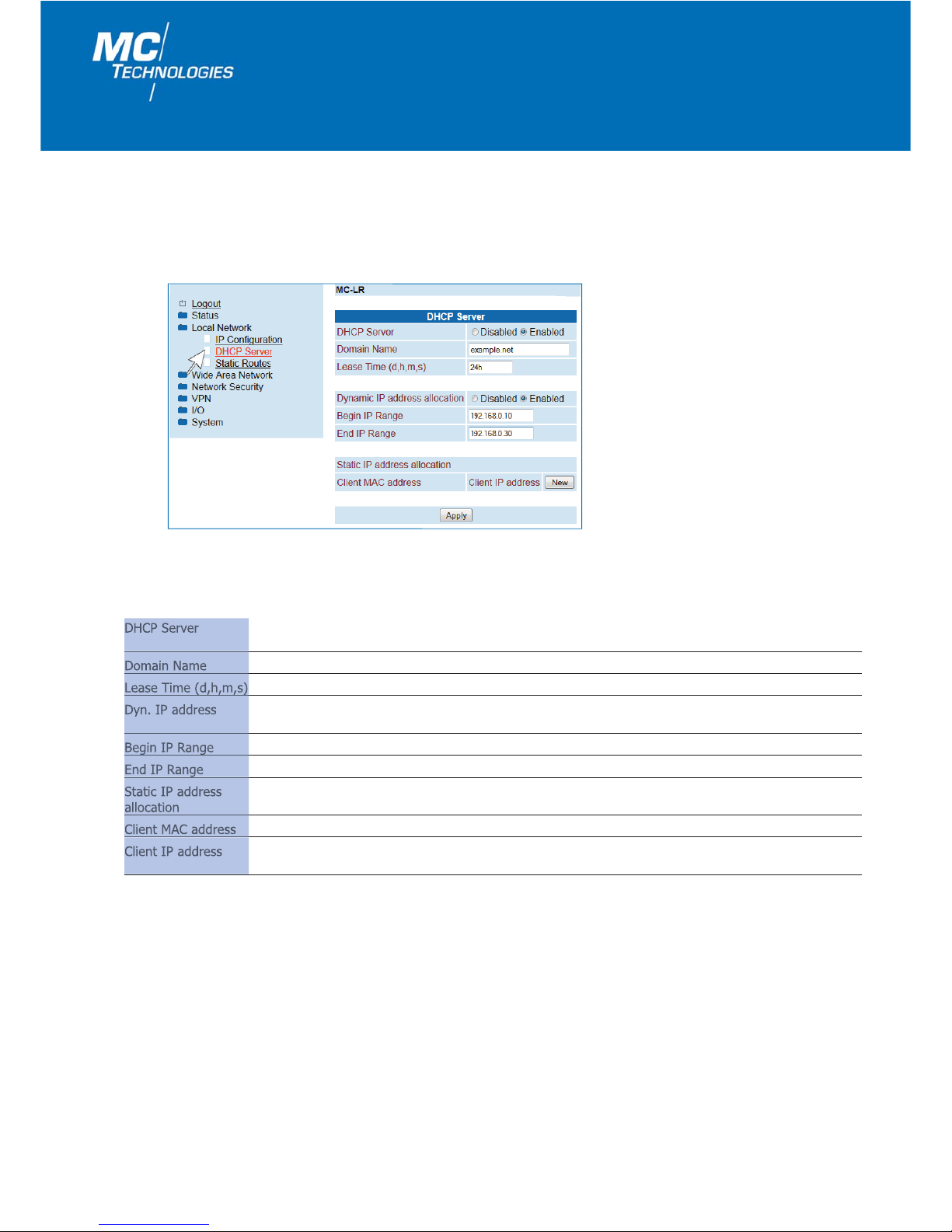
An IP address can be allocated automatically to local equipment connected via Ethernet using DHCP (Dynamic Host
Configuration Protocol).
1.4.2 DHCP Server
8
MC Technologies GmbH
DHCP Server
DHCP Server Disabled/Enabled: Click "Enabled" if the router should allocate the IP addresses to the connected
terminal equipment as the DHCP server at start-up.
Domain Name Domain name to be broadcast via DHCP.
Lease Time (d,h,m,s) Validity period of allocated network configuration.
Dyn. IP address
Disabled/Enabled: Click "Enabled" if an IP address should be dynamically allocated to the connected
terminal equipment in a set range.
Begin IP Range Starting address for the address range from which IP addresses should be distributed.
End IP Range Ending address for the address range from which IP addresses should be distributed.
Static IP address Static allocation of the IP address using the MAC address.
allocation
Client MAC address MAC address of the terminal equipment.
Client IP address IP address of the terminal equipment. Static allocation of the IP addresses should not overlap with the
dynamic IP addresses. An identical IP address should not be used in multiple static allocations.

Data packets from the local network can be defined by static routes using other gateways for alternative routes.
1.4.3 Local Static Routes
9
User Manual/Web Interface MC-LR/MC-LR-4/MC-LRS/MC-LRS-4 – 01/2018 (FW 2.07.3)
Local Static Routes
Network Network in CIDR notation: IP address / Net mask
Example: xxx.xxx.xxx.xxx/yy (x..=IP address; yy=net mask)
Example: yy=24 (number of binary "ones") => net mask = 255.255.255.0
Gateway The gateway how this network can be reached.
10
MC Technologies GmbH
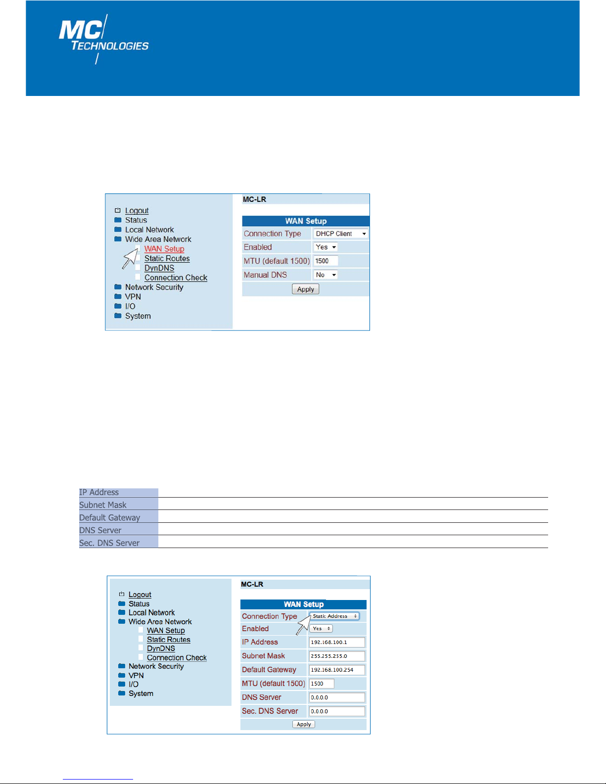
1.5 Wide Area Network
1.5.1 WAN Setup
Settings for use in a WAN (wide area network)
Select the connection type in the
"Connection Type" menu and set "Enabled" to "Yes".
• Static Address
• DHCP Client
• PPPoE
Following this, click
"Apply".
1.5.1.1 Static address - Preferred setting for operation in local networks
A fixed IP address can be assigned to routers which are operating in an existing network.
IP Address The router’s IP address at the WAN interface.
Subnet Mask Subnet mask.
Default Gateway The gateway’s IP address in the Internet.
DNS Server The DNS server’s IP address.
Sec. DNS Server The IP address of a second DNS server.
11
User Manual/Web Interface MC-LR/MC-LR-4/MC-LRS/MC-LRS-4 – 01/2018 (FW 2.07.3)
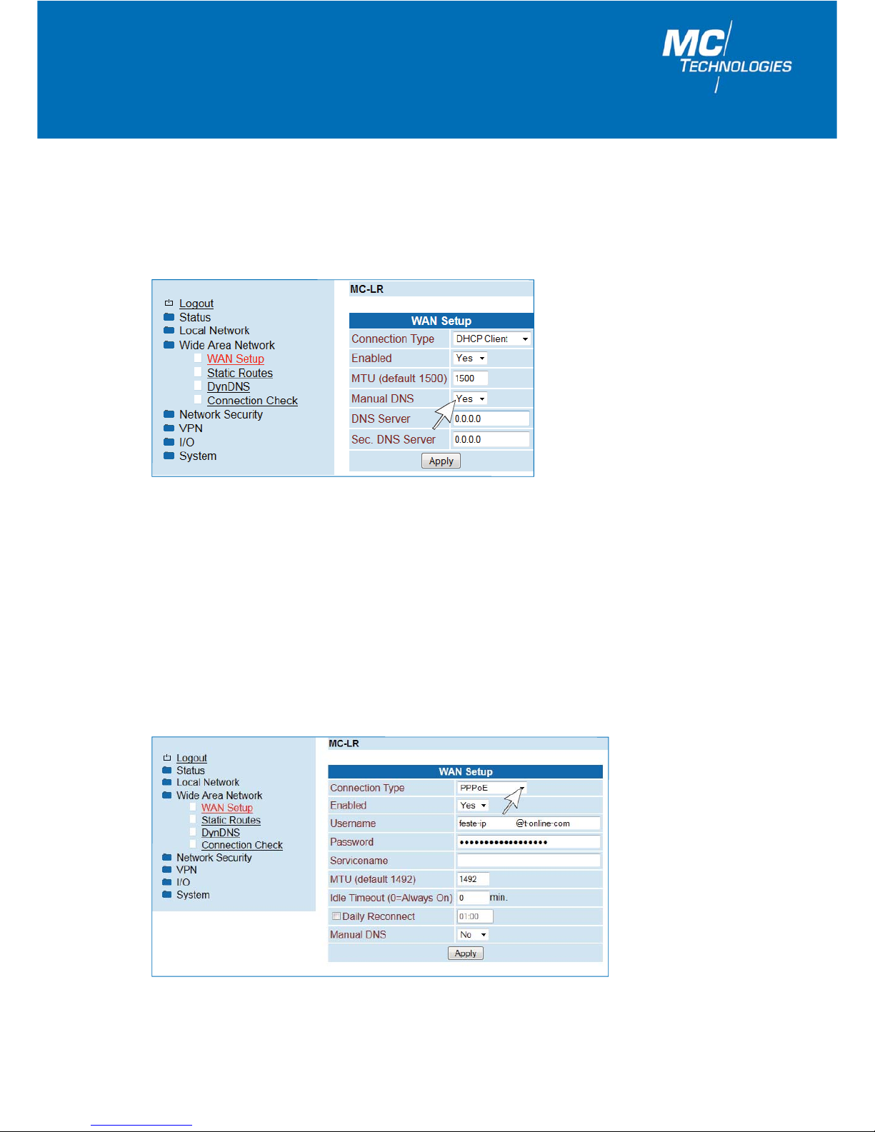
1.5.1.2 DHCP Client - Preferred setting for operation with cable modems and routers
If the router should automatically be assigned with an IP address from the network, set "Connection Type" to "DHCP
Client
" and click "Apply". If you want to manually set the DNS server’s IP addresses, set "Manual DNS" to "Yes" and
enter the IP addresses. Following this, click
"Apply".
1.5.1.3 PPPoE - PPPoE - Preferred setting for operation with DSL modems
For operation with a (DSL-) modem select the "PPPoE" setting under "Connection Type" and click "Apply".
12
MC Technologies GmbH
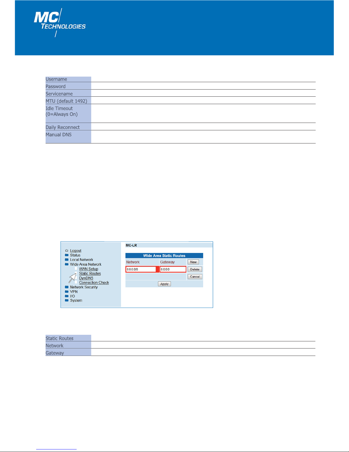
1.5.2 Static Routes
Data packets from the local network can be defined using static routes for alternative routes in the WAN network.
Static Routes
Static Routes
Network Network in CIDR notation.
Gateway The gateway via which this network can be reached.
Username User name for access to the (DSL) network.
Password Password for access to the (DSL) network.
Servicename Service name for access to the (DSL) network.
MTU (default 1492) Maximum size of an unfragmented data package.
Idle Timeout
0: Always On – no termination of the connection.
(0=Always On) Time in minutes: The router terminates the connection at the end of the set time.
The timer starts when data transmission has ended.
Daily Reconnect Repeat logging into the (DSL) network at a defined time.
Manual DNS
Yes: Manual setting.
No: No manual setting.
PPPoE
Complete all settings with
"Apply".
13
User Manual/Web Interface MC-LR/MC-LR-4/MC-LRS/MC-LRS-4 – 01/2018 (FW 2.07.3)
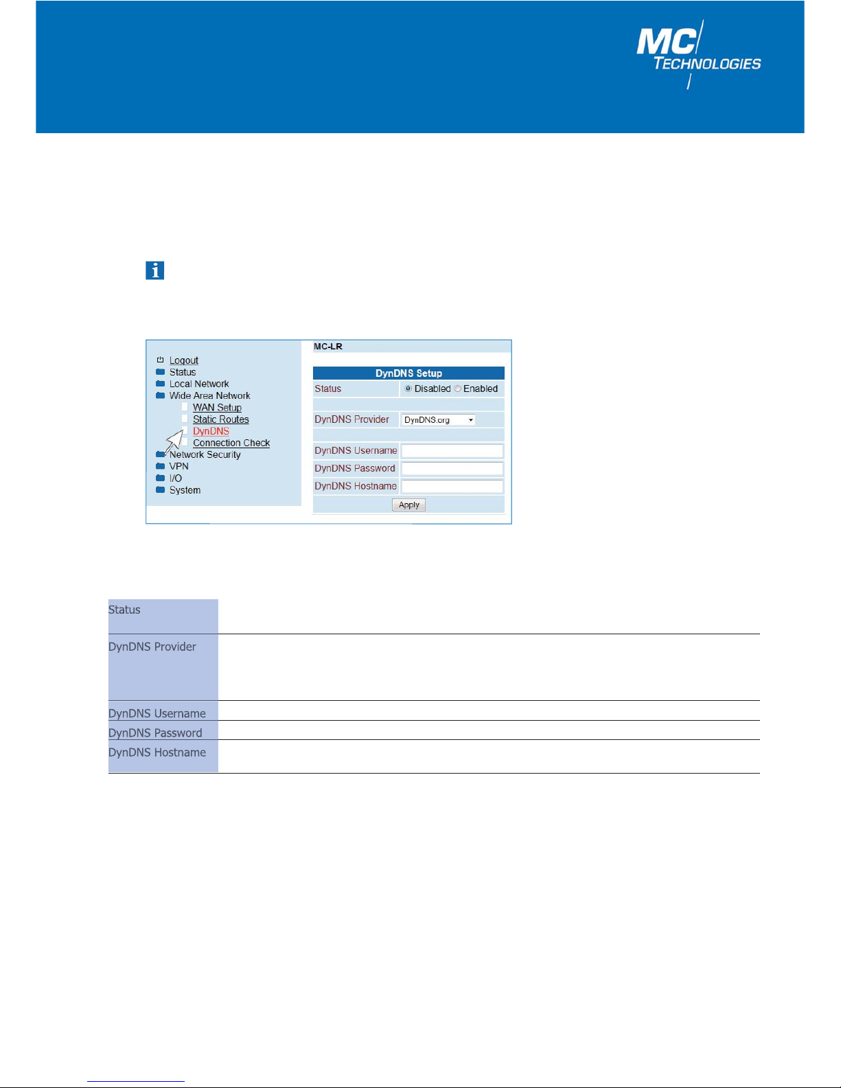
1.5.3 DynDNS
The router IP address in the cellular network/Internet is allocated dynamically by the mobile service operator. A name
can be allocated to the dynamic IP address using a DynDNS provider, via which the router can then be reached over
the Internet. The DynDNS Client must be saved and activated in the router accordingly.
Note: For this to work, the provider must have allocated a public IP address to the router, not a private one.
This is not the case with all providers. DynDNS cannot replace a static IP address and has limited reliability.
DynDNS Set-up
Status Disabled: Deactivate DynDNS client.
Enabled: Activate DynDNS client.
DynDNS Provider Select the name of the provider with whom you are registered,
i.e. DynDNS.org, TZO.com, dhs.org., selfHost.de, custom DynDNS.
Use the "custom DynDNS" setting to select your preferred DynDNS provider.
Please also enter the provider’s server address under "DynDNS Server".
DynDNS Username Enter the username for your DynDNS account here.
DynDNS Password Enter the password for your DynDNS account here.
DynDNS Hostname The host name selected for this router for DynDNS service.
Your router can then be reached under this host name.
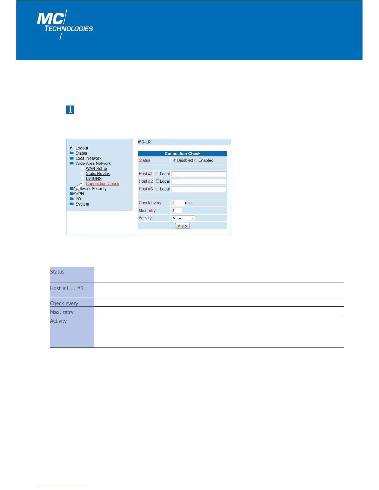
1.5.4 Connection Check
14
MC Technologies GmbH
For continuous connection monitoring, use "Connection Check". If the connection is lost, an action can be configured
for establishing a new connection.
Note: Please note that frequent connection checks can lead to increased data traffic and corresponding costs.
Connection Check
Status Disabled: Connection check is deactivated (default).
Enabled: Connection check is activated.
Host #1 ... #3 IP address or host name of the reference point for the connection check.
"Local" option, when dealing with an address which can be reached via a VPN tunnel.
Check every Check interval in minutes.
Max. retry Number of repetitions until the configured action "Activity" is performed.
Activity
Reboot: Restart the router.
Reconnect: Re-establish packet data connection.
Relogin: Restart the cellular interface by redialing the mobile service network.
None: None.
User Manual/Web Interface MC-LR/MC-LR-4/MC-LRS/MC-LRS-4 – 01/2018 (FW 2.07.3)
15
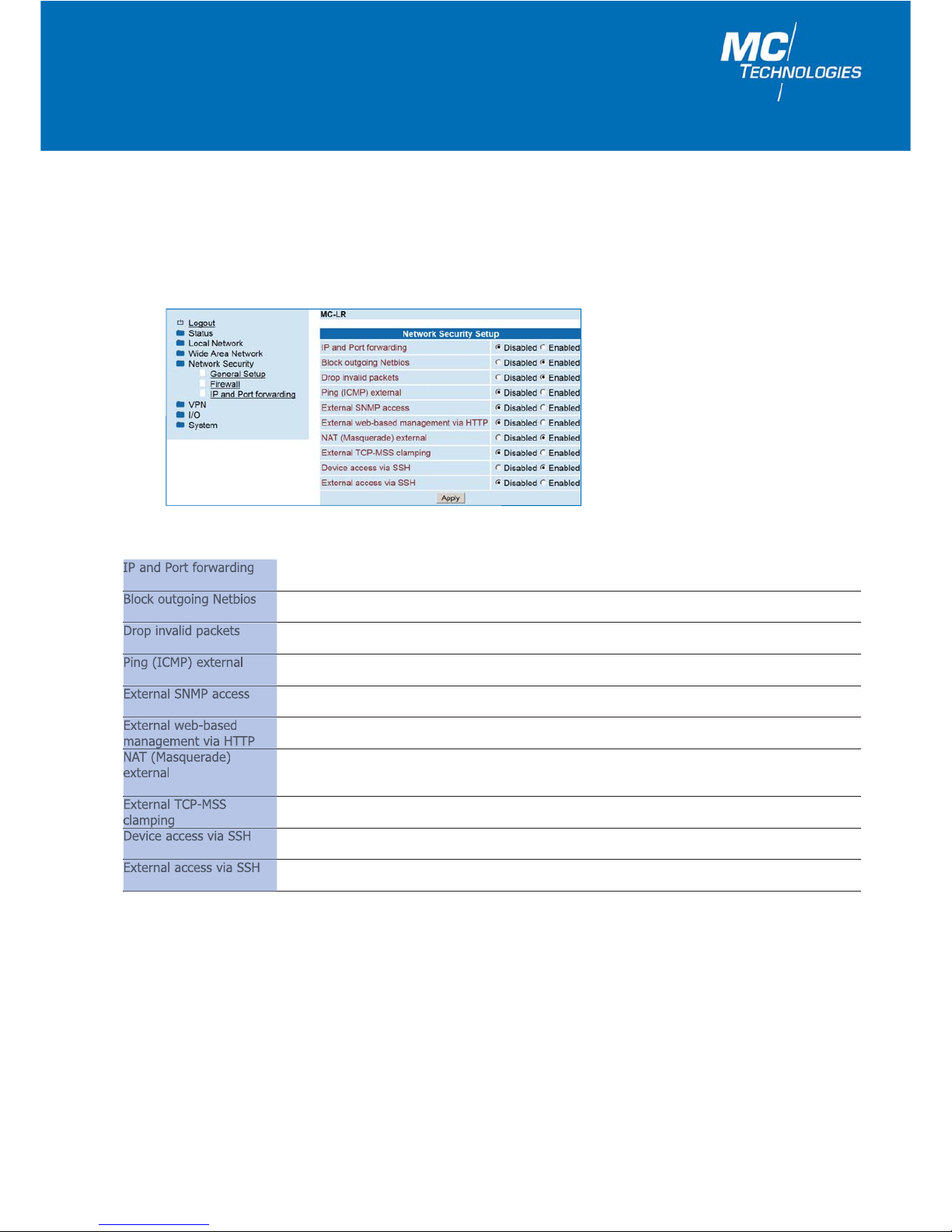
1.6 Network Security
Basic settings for network security.
1.6.1 General Setup
General Setup
IP and Port forwarding Disabled: IP and Port forwarding is blocked.
Enabled: IP and Port forwarding is allowed.
Block outgoing Netbios Disabled: Outgoing NetBIOS requests are allowed.
Enabled: Outgoing NetBIOS requests are blocked (default).
Drop invalid packets Disabled: Packets will be transferred.
Enabled: Invalid packets will be dropped.
Ping (ICMP) external
Disabled: A ping request from the external IP network to the router is ignored (default).
Enabled: A ping request from the external IP network to the router is returned.
External SNMP access Disabled: SNMP from the WAN interface is blocked.
Enabled: SNMP from the WAN interface is permitted.
External web-based Disabled: External configuration via the web interface is not possible.
management via HTTP Enabled: External configuration via the web interface is possible.
NAT (Masquerade) Disabled: No IP masquerading performed.
external Enabled: IP masquerading is activated. Communication from a private, local networkto the
Internet is allowed (default).
External TCP-MSS Disabled: Adjusts the maximum segment size on the WAN side to the MTU value.
clamping Enabled: Reduces the maximum segment size on the WAN side (for DSL operation).
Device access via SSH Disabled: Local SSH access to the router is not possible (default).
Enabled: Local SSH access to the router is possible.
External access via SSH Disabled: Remote SSH access to the router is not possible (default).
Enabled: Remote SSH access to the router is possible.
MC Technologies GmbH
16
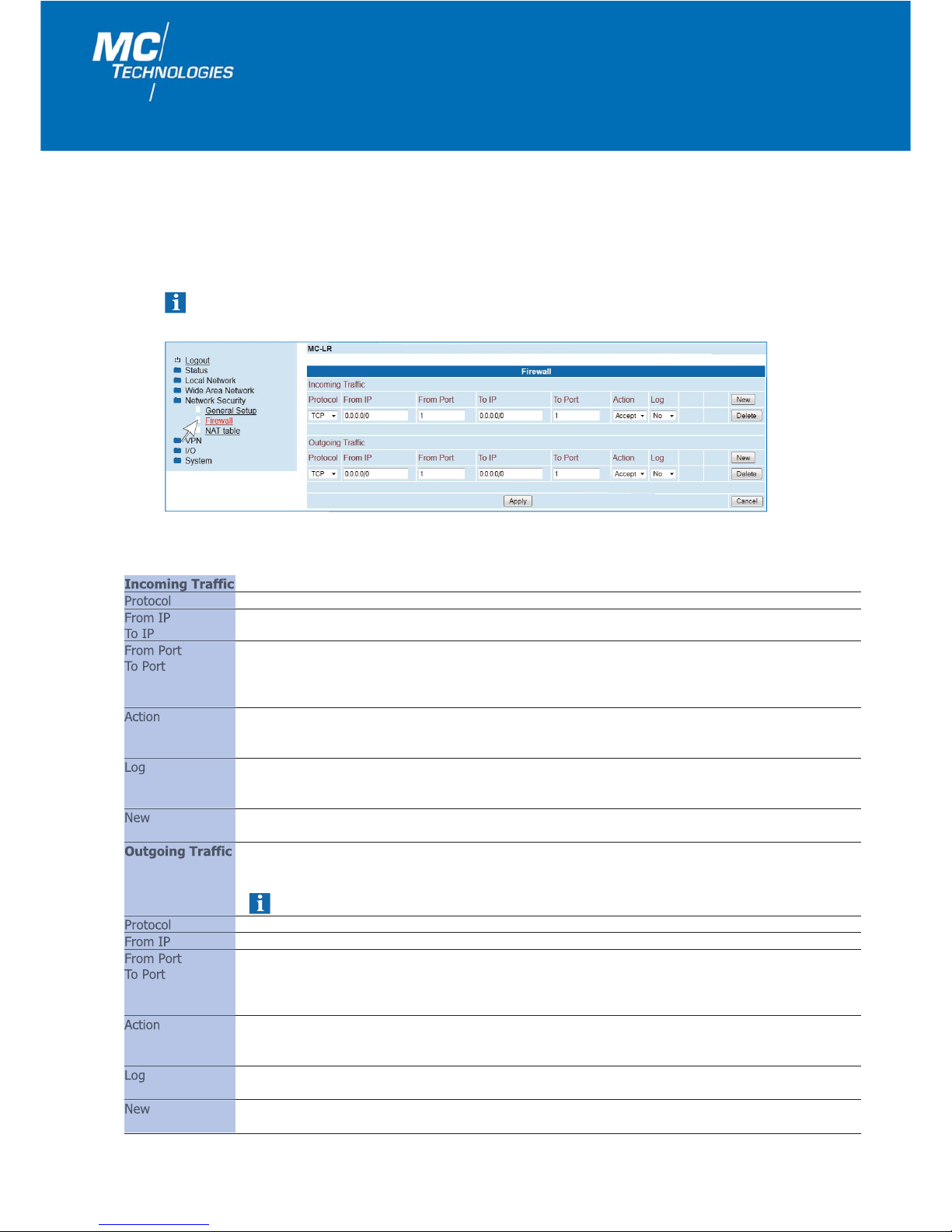
1.6.2 Firewall
The MCT router includes a Stateful Packet Inspection Firewall.
The firewall can be turned on or off (see "Network Security Setup" menu point "Firewall.") The firewall is active by
default and blocks incoming data traffic. Outgoing data traffic is still possible.
The firewall rules are applied from up to down.
Firewall
Incoming Traffic
Protocol TCP, UDP, ICMP, all
From IP 0.0.0.0/0 means all IP addresses. To enter an address range, use CIDR notation.
To IP
From Port (only with TCP and UDP) You have the following options:
To Port 1. Direct port input Example: From Port = 20, To Port = 30.
2. Any Examples: From Port or To Port = Any (Any means absolutely any port).
3. Port range Example: From Port or To Port = 80-90 (all ports from 80-90).
Action
Accept: Pass data packets.
Reject: Data packets are rejected.
Drop: Data packets may not pass, the sender does not receive notification.
Log Logging firewall rules.
Yes: Event is logged.
No: Event is not logged (default).
New A new firewall rule is added below the last rule.
Delete: The rule is deleted.
Outgoing Traffic Lists the installed firewall regulations. They apply for outgoing data connections that were internally
initiated to communicate with a remote destination device.
Factory settings: The factory settings include a rule allowing all outgoing connections.
Note: If no rule is set, all outgoing connections are blocked (except VPN).
Protocol TCP, UDP, ICMP, all
From IP 0.0.0.0/0 means all IP addresses. To enter an address range, use CIDR notation.
From Port (Only evaluated for TCP and UDP logs.) You have the following options:
To Port 1. Direct port input Example: From Port = 20, To Port = 30.
2. Any Examples: From Port or To Port = Any (Any means absolutely any port).
3. Port range Example: From Port or To Port = 80-90 (all ports from 80-90).
Action
Accept: Pass data packets.
Reject: Data packets are rejected.
Drop: Data packets may not pass, the sender does not receive notification. Logging of firewall rules.
Log
Yes: Event is logged.
No: Event is not logged (default).
New A new firewall rule is added below the last rule.
Delete: The rule is deleted.

User Manual/Web Interface MC-LR/MC-LR-4/MC-LRS/MC-LRS-4 – 01/2018 (FW 2.07.3)
17
IP and Port forwarding
Protocol TCP, UDP, ICMP
From IP 0.0.0.0/0 means all IP addresses. To enter an address range, use CIDR notation.
In Port (only with TCP and UDP) You have the following options:
To Port 1. Direct port input Example: In Port = 20, To Port = 30.
2. Port range Example: In Port = 80-90, To Port = 100-110.
To IP 0.0.0.0/0 means all IP addresses. To enter an address range, use CIDR notation.
Masq For every individual rule, you can determine if IP masquerading should be applied.
Yes: IP masquerading is activated, reply to cellular network is possible.
No: (default) No reply to the Internet is possible.
Comment Entering a comment.
Log Logging firewall rules.
Yes: Event is logged.
No: Event is not logged (default).
New The "New" button allows a new rule to be added under the last rule.
The "Delete" button deletes the rule from the table.
Rules for IP and port forwarding.
The router only has a single IP address which can be used to access it from outside the network.
The additionally transmitted port number can be used to re-direct data packages to ports with internal IP addresses.
1.6.3 IP and Port forwarding
Note: After clicking "Apply" carry out a reboot (see Page 41) or restart the router (interrupt the power supply).
MC Technologies GmbH
18
1.7 VPN
For a VPN connection, the IP addresses of the VPN remote peers must be known and addressable.
The VPN remote peer must support IPsec with the following configuration:
– Authentication by X.509 certificates or Preshared Secret Key (PSK)
– ESP
– Diffie-Hellman Group 2 or 5
– 3DES or AES encryption
– MD5 or SHA-1 hash algorithms
– Tunnel mode
– Quick mode
– Main mode
– SA lifetime (1 second to 24 hours)
IPsec (Internet Protocol Security) is a security protocol used for communicating over IP networks.
1.7.1 IPsec
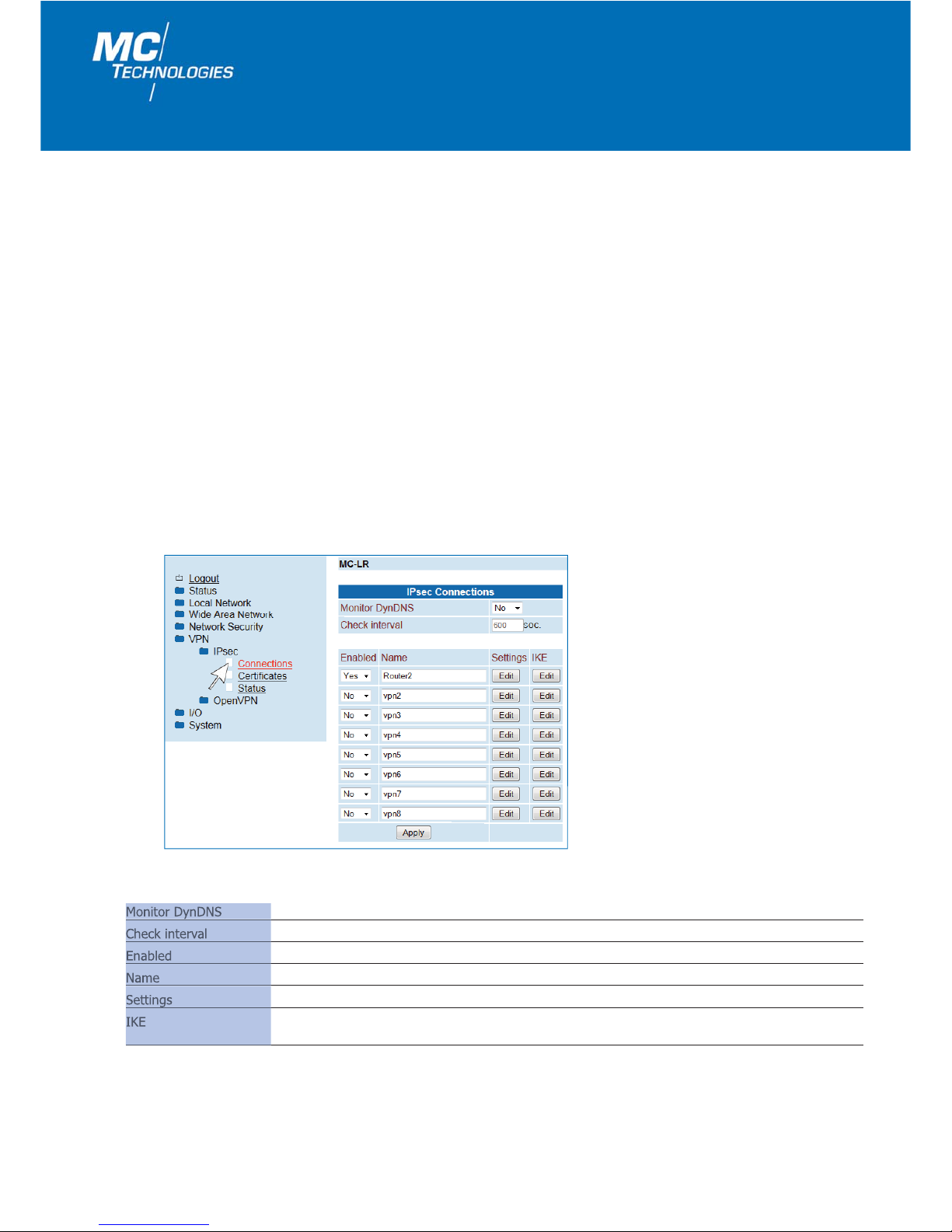
IPsec Connections
Monitor DynDNS If DynDNS is used as "Remote Host", the "Monitor DynDNS" function should be set to "Yes".
Check interval Check interval in seconds.
Enabled Activate or deactivate VPN connection.
Name Arbitrary name of VPN connection.
Settings VPN connection settings.
IKE The "Edit" menu includes settings to establish IKE (Internet Key Exchange protocol) automatic key
management for IPsec (see Page 25).
1.7.1.1 Connections

User Manual/Web Interface MC-LR/MC-LR-4/MC-LRS/MC-LRS-4 – 01/2018 (FW 2.07.3)
19
IPsec Connection Settings > Edit
IPsec Connection Settings
Name Name of the VPN connection.
VPN Active = Enabled, Inactive = Disabled.
Authentication
X.509 Remote Certificate: Each VPN participant has a private, secret key as well as a public key in
the form of a X.509 certificate which contains further information about its
owner and a certification authority (CA).
Preshared Secred Key (PSK): Each VPN participant knows a shared password.
X.509 Remote + CAuth: Like an X.509 certificate but with entry of the user name and password
(e.g. when using Shrew Soft as a VPN client).
Remote Certificate VPN remote peer certificate. The certificate must be loaded ahead of time.
Local Certificate Local certificate with which the router identifies itself to the VPN remote peer (machine certificate,
PKCS#12.) The certificate must be loaded ahead of time.
Remote ID If the field is left empty (default,) the information from the certificate is used.
Name for identification by remote peer. This must correspond to the information from the router
certificate.
Local ID If the field is left empty (default,) the information from the certificate is used.
The local ID allows you to set the name with which the router identifies itself to the remote peer.
For more details, see Remote ID.
Virtual Remote Virtual remote IP address when using clients that cannot connect networks
Address (e.g. PC with Shrew Soft VPN software, smartphones, etc.).
Address Remote IP address/subnet mask of the remote network to which the VPN connection needs to be established.
Network
MC Technologies GmbH
20
IPsec Connection IKE > Edit
IPsec Connection Settings
Address Local IP address/subnet mask of the local network.
Network
Connection NAT
None: No NAT on other IP addresses.
Local 1:1 –NAT -> NAT to local Network: 1 to 1 NAT on the local network.
Setting of the start IP address.
Remote Connection Direction of connection establishment:
Accept: Wait for the remote peer to establish the connection.
Initiate: The router establishes the connection.
Initiate on SMS: Connection established after reception of valid SMS.
Initiate on Call: Connection established after valid call.
Iniatiate on Input: Connection established after switch signal on IN of the I/O interface.
Autoreset Click here and set a time in minutes after which the connection should be automatically disconnected.

User Manual/Web Interface MC-LR/MC-LR-4/MC-LRS/MC-LRS-4 – 01/2018 (FW 2.07.3)
21
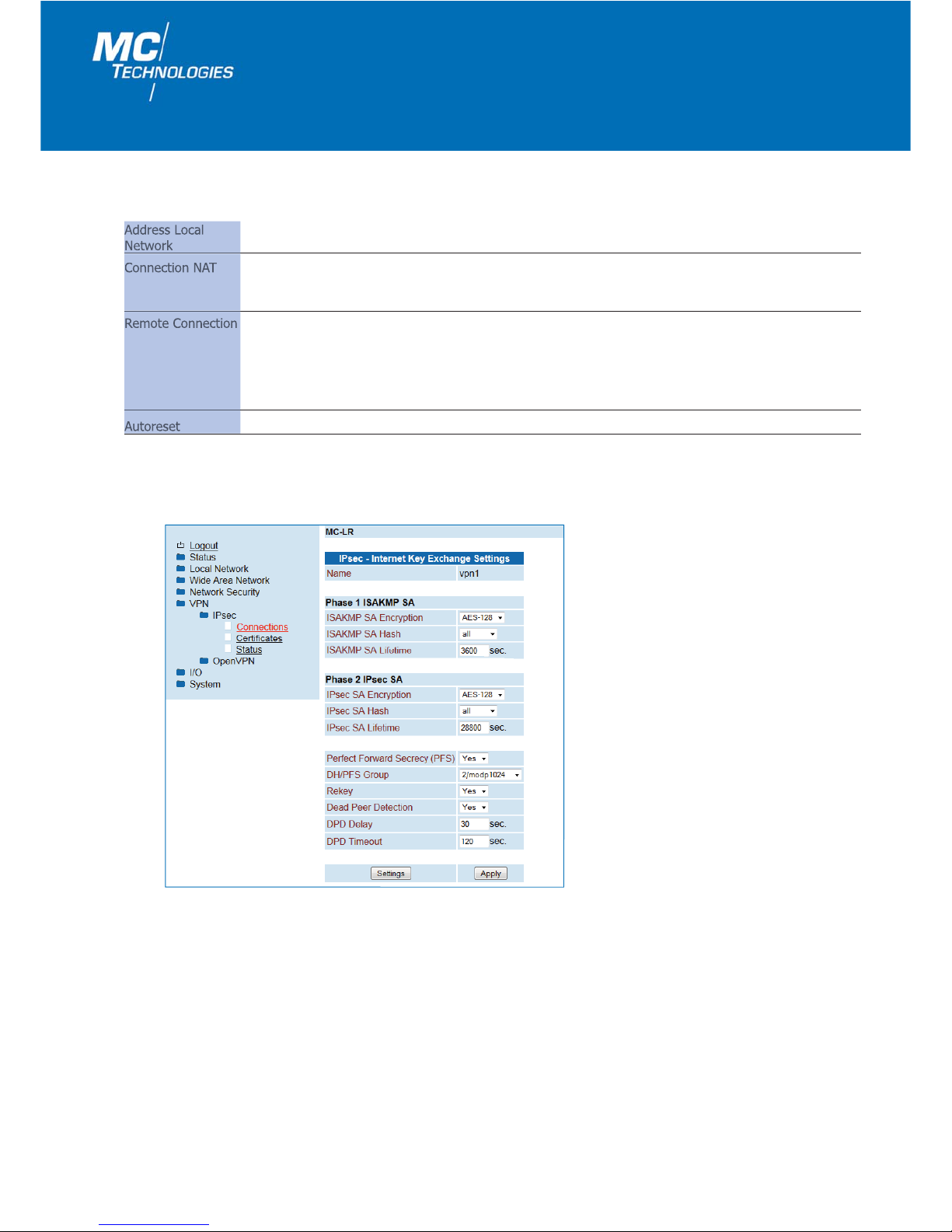
IPsec Connection IKE
IPsec - Internet Key Name of the VPN connection.
Exchange Settings
Phase 1 ISAKMP SA
ISAKMP SA Encryption AES-128 (default). AES-192, AES-256, 3 DES.
ISAKMP SA Hash The setting "all" accepts either MD5 or SHA-1.
ISAKMP SA Lifetime Life cycle of a key in seconds (3600 = 1 hour).
Phase 2 IPsec SA Unlike Phase 1 ISAKMP SA (key exchange,) this is where the procedure for Data exchange is
determined. It can differ from the key exchange procedure.
IPsec SA Encryption AES-128 (default). AES-192, AES-256, 3 DES.
IPsec SA Hash The setting "all" accepts either MD5 or SHA-1.
IPsec SA Lifetime Life cycle in seconds for the key specified for IPsec SA.
28800 seconds = 8 hours (default).
86400 seconds = 24 hours (maximum).
Perfect Forward
Yes: Perfect Forward Secrecy activated.
Secrecy (PFS) No: Perfect Forward Secrecy deactivated.
DH/PFS Group Key exchange procedure (Diffie-Hellman groups for Internet Key Exchange (IKE)).
5/modp1536 = High encryption.
2/modp1024 = Normal encryption (default).
Rekey
Yes: A new key will be brokered.
No: No new key will be brokered.
Dead Peer Detection Recognition of validity and resulting action in case of interruption of IPsec connection.
Yes: Dead Peer Detection activated (i.e. Restart at VPN Initiate).
No: No Dead Peer Detection.
DPD Delay Time interval to next check.
DPD Timeout Time period after which the connection to the remote peer should be declared inactive.
Default value: 120 seconds.
Maximum: 86400 seconds (24 hours).

MC Technologies GmbH
22
1.7.2 OpenVPN
1.7.2.1 Connections (Tunnel 1 and 2 / Clients)
1.7.1.3 Status
1.7.1.2 Certificates
The router authenticates itself to the remote peer with a certificate that can be uploaded onto the router.
By clicking "Apply", you upload the certificate onto the router.
Certificates
Load Remote Upload - Upload the remote peer certificate (.cer .crt).
Certificate Under VPN > IPsec > Connections > Settings > Edit, you assign the certificate for the VPN
connection.
Load Own PKCS#12
Upload - Upload the certificate (in PKCS#12 format, xxx.p12) to be used for the local router.
Certificate Under VPN > IPsec > Connections > Settings > Edit, you assign the certificate to the
VPN connection.
Password - Enter the password given during exporting.
Remote Certificates List of imported .cer /.crt certificates.
Delete - Delete a certificate.
Own Certificates List of imported PKCS#12 certificates
Delete - Delete a certificate.
IPsec Status
Active IPsec An active VPN connection is indicated by a green symbol.
Connections
OpenVPN establishment of a virtual private network (VPN) via an encrypted connection.
Two OpenVPN tunnels can be set up at the same time (Tunnel 1 and Tunnel 2.)
The configuration of Tunnel 1 and Tunnel 2 is identical.
Additionally, 2 OpenVPN Bridge-Connections can be established at the same time.

User Manual/Web Interface MC-LR/MC-LR-4/MC-LRS/MC-LRS-4 – 01/2018 (FW 2.07.3)
23
OpenVPN Connections
OpenVPN Tunnel
Proxy None: No proxy is used.
http: An http proxy either with or with authentication is used.
socks: A socks proxy either with or with authentication is used.
Proxy Server Proxy server’s URL or IP address.
Proxy Port Proxy server’s port.
Username User name for authentication.
Password Password for authentication.
Select an OpenVPN connection and click "Edit".
If your Internet connection is via a proxy server, you can carry
out the required settings here.
OpenVPN Proxy settings
OpenVPN Bridge
Name Arbitrary name of OpenVPN connection.
VPN
Enabled: OpenVPN Tunnel activated.
Disabled: OpenVPN Tunnel deactivated.
Remote Host IP address or URL of the remote peer to which the tunnel will be established.
Remote Port Port of the remote peer to which the tunnel will be established (default 1194).
Device Type TAP for a TAP-OpenVPN-Connection, TUN for a TUN-OpenVPN-Connection.
Protocol Protocol selection (UDP or TCP).
LZO Compression
Disabled: Switched off or not allowed.
Adaptive: (Data) adaptive compression switched on.
Yes: Switched on but can be switched off from the server.
No: Switched off but can be switched on from the server.
Enabled: Compression allowed; type of compression determined by the server.
Allow Remote Float Activate this option to accept authenticated packets from each IP address during OpenVPN
connection. This option is recommended if IP addresses are used for dynamic communication.
Redirect Default The default gateway is directed via the tunnel.
Gateway
Local Port Determines a fixed port for the OpenVPN client.
MC Technologies GmbH
24
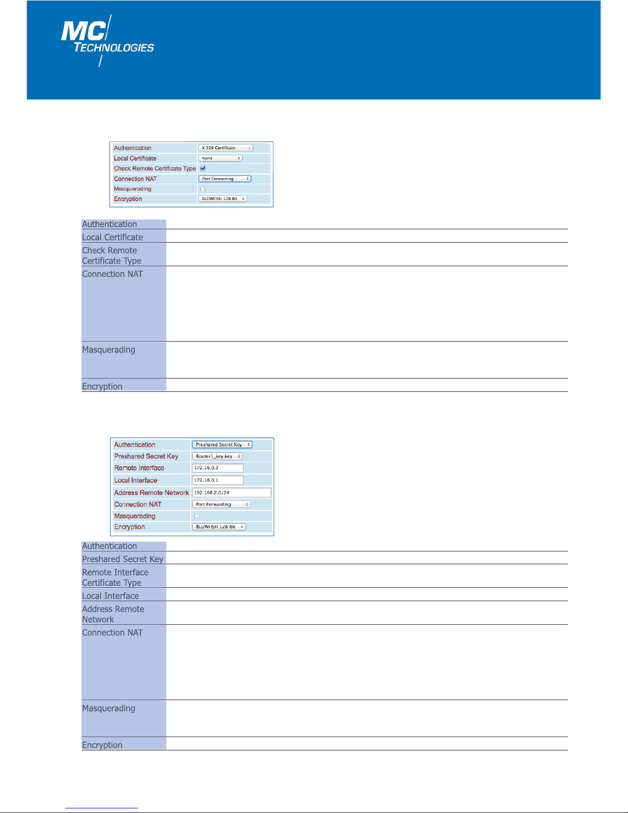
OpenVPN X.509 Certificate
OpenVPN Preshared Secret Key
Authentication X.509 Certificate - Authentication procedure for X.509 certificate.
Local Certificate Ascertains which certificate the router will use to identify itself to the VPN remote peer.
Check Remote Activate this option to check the OpenVPN connection certificates.
Certificate Type
Connection NAT
None: No forwarding.
Local 1:1 NAT: "One-to-one" forwarding to a local network (NAT to local network).
Local Masquerding: The packets going out through the tunnel are rewritten to the router source
address so that equipment on the router can access the other side of the tunnel.
Port Forwarding: Forwarding with the setting described under 1.7.2.2.
Host Forwarding: Forwarding to the fixed IP address of a connected terminal device (Forward to
local Host).
Masquerading
Only with the setting "Connection NAT" "Port Forwarding" or "Host Forwarding":
Packages leaving via the tunnel are rewritten to the router’s source address to allow devices connected
to the router to access the other end of the tunnel.
Encryption Encryption algorithm for the OpenVPN connection.
Authentication Preshared Secret Key – authentication procedure with a static key (Preshared Key).
Preshared Secret Key Ascertains preshared secret key the router uses to identify itself to the VPN remote peer.
Remote Interface Virtual, remote IP address of the remote peer certificate type.
Certificate Type
Local Interface Virtual local IP address of the router.
Address Remote Address range of the remote network.
Network
Connection NAT
None: No forwarding.
Local 1:1 NAT: "One-to-one" forwarding to a local network (NAT to local network).
Local Masquerding: The packets going out through the tunnel are rewritten to the source address of
the router to allow equipment on the router access to the other side of the tunnel.
Port Forwarding: Forwarding with the setting described under 1.7.2.2.
Host Forwarding: Forwarding to the fixed IP address of a connected terminal device (Forward to
local Host).
Masquerading
Only with the setting "Connection NAT" "Port Forwarding" or "Host Forwarding":
Packages leaving via the tunnel are rewritten to the router’s source address to allow devices connected
to the router to access the other end of the tunnel.
Encryption Encryption algorithm for the OpenVPN connection.

User Manual/Web Interface MC-LR/MC-LR-4/MC-LRS/MC-LRS-4 – 01/2018 (FW 2.07.3)
25
OpenVPN Username / Password
Keep Alive
Authentication Username/Password - Set-up of user name and password.
CA Certificate Enter the OpenVPN server CA certificate.
Check Remote Specifying whether the remote certificate should be evaluated.
Certificate Type
Username Enter user name.
Password Ente password.
Connection NAT
None: No forwarding.
Local 1:1 NAT: "One-to-one" forwarding to a local network (NAT to local network).
Local Masquerading: The packets going out through the tunnel are rewritten to the router source
address so that equipment on the router can access the other side of
the tunnel.
Remote Masquerading: The packets coming in through the tunnel are rewritten on the local router
address.
Port Forwarding: Forwarding with the setting described under 1.7.2.2.
Host Forwarding: Forwarding to the fixed IP address of a connected terminal device (Forward to
local Host).
Masquerading
Only with the setting "Connection NAT" "Port Forwarding" or "Host Forwarding":
Packages leaving via the tunnel are rewritten to the router’s source address to allow devices connected
to the router to access the other end of the tunnel.
Encryption Encryption algorithm for the OpenVPN connection.
Keep Alive Time period in seconds after which Keep Alive requests should be sent. These requests test whether
the remote peer is still available.
Default setting: 30 seconds.
Restart Time period in seconds after which the connection to the remote peer should be restarted if there is
no reply to the Keep Alive requests.
Default setting: 120 seconds.

MC Technologies GmbH
26
1.7.2.2 Connections Server (only for MC-LR SERVER)
The OpenVPN server function is only supported by the MC-LR SERVER LAN router.
In this case, an enhanced menu is available for configuration of OpenVPN connections.
OpenVPN Client OpenVPN Client and Server
Configuration of the OpenVPN server
To activate the server, select the "Yes" option for the "Enabled" menu item. Enter your chosen server name under
"Name". Following this, click "Apply". Click "Edit" to access the OpenVPN server settings.
User Manual/Web Interface MC-LR/MC-LR-4/MC-LRS/MC-LRS-4 – 01/2018 (FW 2.07.3)
27
VPN Disabled: VPN not activated.
Enabled: VPNactivated.
Local Port OpenVPN port setting for the server (default 1194).
Protocol Protocol setting (UDP or TCP).
LZO Compression Disabled: Disabled or not permitted.
Adaptive: Adaptive OpenVPN compression is activated.
No: OpenVPN compression is disabled.
Yes: OpenVPN compression is activated.
TLS Authentication Used to select a common TLS authentication key which has been uploaded in advance under
Key Certificates.
Local Certificate Used to select the OpenVPN server’s PKCS#12 certificate (.p12). The certificate must be uploaded in
advance.
Note: Please ensure that the router’s system time is current and thus falls within the
chronological validity window for the certificates.
Diffie-Hellman The default setting is 1024 Bit, however can be changed to 2048 Bit here (is defined when creating
Parameter the certificate).
Encryption Encryption algorithm for the OpenVPN connection.
Client to Client Traffic Used to block or permit client-to-client traffic.
Client Subnet Base Specification of the OpenVPN server’s base network.
This setting is used to automatically derive the clients’ network segments
(see Setting: Client table below).
Virtual Network Base Specification of the OpenVPN server’s internal, virtual base network. This setting is used to
automatically derive the clients’ virtual IP addresses (see Setting: Client table below).
Keep Alive Time span in seconds after which keep alive queries should be sent. These queries test whether the
remote peer is still available.
Factory setting: 30 seconds.
Restart Time span in seconds after which the connection to the remote peer should be restarted if the keep
alive queries were not answered.
Factory setting: 120 seconds.
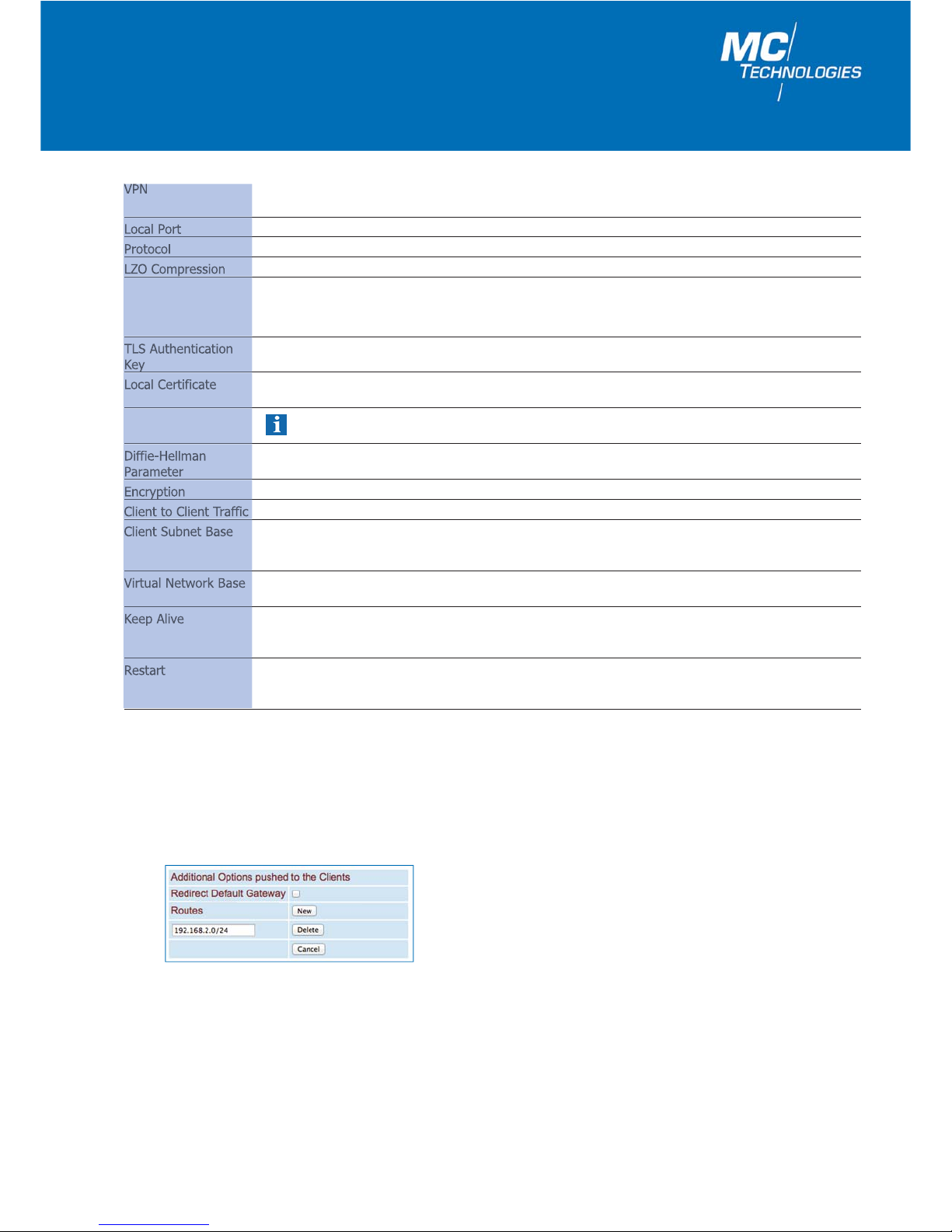
Additional Options pushed to the Clients
Can be used to provide clients with information about routes. Click "Redirect Default Gateway" to direct client routes via
the OpenVPN tunnel.

MC Technologies GmbH
28
Example based on the illustration above: A client has loaded a certificate with the common name LAB2. This client can
then be accessed under virtual IP address 172.16.0.5. The network on the client (router) can be accessed via the IP
address segment 192.168.2.0/24.
Click the "Clients" button to create OpenVPN clients.
Note:
The client address is automatically derived from the Virtual Network Base setting under: "OpenVPN Server".
(e.g. Virtual network base = 172.16.0.0/24,
First client address = 172.16.0.5,
Second client address = 172.16.0.9, etc.)
The client subnet is automatically derived from the Client Subnet Base setting under: "OpenVPN Server".
(e.g. Virtual network base = 192.168.1.0/24,
First client subnet = 192.168.2.0./24,
Second client subnet = 192.168.3.0/24, etc.)
Please define your OpenVPN clients here. To enable the OpenVPN server to identify clients, you must enter the common name which was defined for the client when generating the corresponding certificate under the "Common Name"
menu item here. This feature is thus used to assign the client certificate to the client address defined by the server.

User Manual/Web Interface MC-LR/MC-LR-4/MC-LRS/MC-LRS-4 – 01/2018 (FW 2.07.3)
29
Click "Advanced" for additional special settings.
Where required, you have options to create special settings for sizes: TUN-MTU, Fragment, MSS fix and for the renegotiate key interval.
Important note:
Please remember to confirm/activate all entries or changes by clicking the "Apply" button. Should the settings not
be immediately effective, then you should reboot the router for good measure.
1.7.2.3 Port Forwarding
Protocol TCP, UDP, ICMP
In Port / To Port (TCP and UDP only) You have the following options:
To Port 1. direct port input - Example: In Port = 20, To Port = 30.
2. Port range - Example: In Port = 80-90 To Port = 100-110.
To IP Input of a target IP address, 0.0.0.0/0 means all IP addresses.
Masq For every individual rule, you can determine if IP masquerading should be applied.
Yes: IP masquerading is activated, reply to VPN tunnel is possible.
No: (Default) reply to VPN tunnel is not possible.
Comment Input comment.
Rules for Port Forwarding: The router has only one IP address via which it can be accessed externally.
Data packets can be redirected to internal IP address ports via additional transmitted port numbers.

1.7.2.5 Static Keys (Preshared Key)
MC Technologies GmbH
30
1.7.2.4 Certificates
Certificate for authentication of the router to the remote peer.
Certificates
Load Own PKCS#12 Upload Upload the certificate (in PKCS#12 format, xxx.p12) to be used for the local router.
Under VPN > OpenVPN > Client, you can assign one of these certificates to each
VPN connection under Local Certificate.
Password Password with which the PKCS#12 file is protected during export.
Load CA certificate
Upload Upload the CA certificate.
(.crt)
Own Certificate Name Display the uploaded certificates and keys.
CA Certificate Name Display the uploaded CA certificates and keys.
Static Keys
Generate static Key Click on "Save" to generate and save a static key file.
Load static Key
Upload: Upload the static key file. The same file must be uploaded to the remote peer's
OpenVPN server.
Static Keys List of uploaded static key files.

User Manual/Web Interface MC-LR/MC-LR-4/MC-LRS/MC-LRS-4 – 01/2018 (FW 2.07.3)
31
1.7.2.6 Status
OpenVPN status for MC-LR servers
Shows the status of all client connections (see Page 28) to the OpenVPN Server (example: see "LABSERVER" as server
name below).
Name Name of the logged-in OpenVPN client.
Remote Host Sender IP address of the client from the server perspective.
Client Address Virtual client address in the internal OpenVPN network. The client address is created as a link and
serves as a direct connection to the connected client’s Web server (if there is one).
Client Subnet Client’s network address segment.
Status
Status Green symbol: The client is connected.
Red symbol: The client is not connected.
OpenVPN Status
Active OpenVPN Status of the active VPN connection.
Connections

MC Technologies GmbH
32
1.8 I/O
The router switch output can be controlled remotely or switched using a router connection status.
1.8.2 Outputs
The switch input can be used to send emails. Please check to see if the switch input is already being used to start a
VPN connection. If so, it will not be possible to use it to send emails.
1.8.1 Inputs
Note: To send an email, the email account under the section 1.9.8 (see Page 40-41) SMTP Configuration must
be set up.
The router has an I/O input and output (Input/Output).
Inputs
High E-Mail: If activated, an email will be sent when there is a "High" level on the switching input.
Select "E-Mails" and click "Apply".
Following this, click "Edit" and fill out the email form.
None: No email is sent.
Low E-Mail: If activated, an email will be sent when there is a "Low" level on the switching input.
Select "E-Mails" and click "Apply".
Following this, click "Edit" and fill out the email form.
None: No email is sent.

User Manual/Web Interface MC-LR/MC-LR-4/MC-LRS/MC-LRS-4 – 01/2018 (FW 2.07.3)
33
1.8.3 Socket Server
Outputs
Functions Manual: Switch the output by clicking ON or OFF in the web interface.
Remote Controlled: Switch the switch output remotely by SMS (see Page 13) or by
Control command to the socket server (see page 14).
VPN Service: The switch output is active when the router has established a VPN connection.
Connection Lost: The switch output is active when the router connection check
does not reach the configured address.
Autoreset "Autoreset" resets the switch output after the preset period of time.
The router includes an integrated socket server and can be made to perform the following actions by receiving XML files:
1. Set and query I/O signals
2. Send email messages
3. Query the router status
To use these functions, the socket server must be set to "Enabled" in the socket configuration. The socket server port
can be configured as desired, the default setting is Port 1432.
For examples of sending and receiving I/O status, email and router status using XML files via the router socket server
see Section 2.2.1 (Page 47).

MC Technologies GmbH
34
1.9 System
1.9.1 Hardware
This section provides information on the hardware, software and status of the router.
Hardware Information
Address Address of the manufacturer.
Internet Internet address of the manufacturer.
Type Article description of the router.
Serial number Serial number of the router.
Hardware Hardware version of router.
Release version Release version of router software.
Operating system Version of operating system.
Web-based management Version of web interface.
MAC address LAN1 MAC address of Ethernet Connection 1.
MAC address LAN2 MAC address of Ethernet Connection 2.

User Manual/Web Interface MC-LR/MC-LR-4/MC-LRS/MC-LRS-4 – 01/2018 (FW 2.07.3)
35
This menu item lists all the software modules installed, including their versions.
1.9.2 Software
The router web interface can normally be reached via the browser without additionally indicating a port
or by additionally indicating Port 80. The port can be changed here if needed.
Example using router address 192.168.0.1:
Web interface address: 192.168.0.1 or 192.168.0.1:80
1.9.3 System Configuration
Web Configuration
Hostname
The hostname of the WAN Interface can be changed here.
After changing the port to, for instance,
8080 address of the web interface: 192.168.0.1:8080
Note: After clicking "Apply", perform a reboot (Page 44) or restart the router (interrupt the power supply).

MC Technologies GmbH
36
Log Configuration
The router web interface can be accessed via http or https (secure) and/or http + https.
Web server access
Web server access
Web server access http: http access only.
http + https: http and https access.
https: https access only.
HTTPS port (default443) Change the https default port here.
Certificate validity Validity of the https certificate in days.
HTTPS certificate
Renew certificate: Local generation of an https certificate.
Click again to renew the certificate.
Important note! This function is only supported by 4-port routers (MC xx-4) or 2 port routers (MC xx) with
firmware beginning with 2.xx.x (See: "System / Hardware / Release" e.g. 2.04.2).
Log files can be saved on an external log server via UDP.
Log Configuration
Remote UPD logging Disabled: No logging on external server.
Enabled: Logging on external server.
Server IP address Server IP address.
Server Port (default 514) Server port.
Non volatile log
Disabled: Logging on the internal RAM.
USB stick: Logging on the USB stick on the front plate.
SD card: Logging on internal SD card. The SD card is not included in the scope of delivery.

User Manual/Web Interface MC-LR/MC-LR-4/MC-LRS/MC-LRS-4 – 01/2018 (FW 2.07.3)
37
Load configuration
Load configuration Disabled: Uploading of the configuration from a USB stick or internal SD card is deactivated.
USB stick: A configuration from a USB connected to the router has been uploaded.
SD card: A configuration from the internal SD card has been uploaded.
If the upload was successful, the setting is automatically set to "Disabled". The setting
must be reconfigured to USB stick or SD card for a new upload.
Note: The internal SD card slot is accessible by removing the back cover.
Configuration unlock
once: The configuration is only uploaded once from the storage medium (USB stick
or SD card).
always: The configuration is always uploaded from the storage medium (USB stick or SD card)
after the router is booted.
by Input 1:The configuration is uploaded from the storage medium (USB stick or SD card) when
there is a High signal from the input (I/O).
Load Configuration
Click "Apply" to save your configuration.
To reconfigure the router using the default IP address or to set the configuration to the factory default settings you will
need to use the configuration button on the rear side of the device (See Item 1.2.2). The following settings allow you
to define which function should be permanently assigned to the configuration button.
Reset button
Reset button
Reset button Web access reset: Press the reset button to readdress the router web interface using the default IP
address (192.168.0.1) for the Ethernet (LAN) connection. The configuration
settings will not be lost when doing so.
Factory reset: Press the reset button to readdress the router web interface using the default IP
address (192.168.0.1) for the Ethernet (LAN) connection. All configuration
settings will be deleted and reset to "Factory Default".
Click "Apply" to save your configuration.

MC Technologies GmbH
38
1.2.2 Local IP address is not (no longer) known – configuration button
Should you not have changed the default setting, then the router will be set to "Web access reset". Use a pointed object to press the configuration button for at least 5 seconds. The router’s Web interface can now temporarily be readdressed using the default IP address (192.168.0.1) to the Ethernet (LAN) connection. The configuration settings will
not be lost when doing this.
Web access reset
Note: The router does not supply an IP address to the connected PC via DHCP. You should thus set the PC to
a fixed IP address (e.g. 192.168.0.2, default gateway 192.168.0.1).
You now have access to Web management with the default access information. Please check the settings for the
router’s IP address, user name and password and make any necessary changes.
Factory reset
You changed the setting to factory reset (see Item 1.9.3 System configuration / Reset button). Use a pointed object to
press the configuration button for at least 5 seconds. The router’s Web interface can now be readdressed using the
default IP address (192.168.0.1) to the Ethernet (LAN) connection.
Note: All configuration settings will be deleted and reset to the "Factory Defaults" setting.
1.2.3 Resetting of all settings in the Web interface
Resetting of all router settings to the factory defaults can be carried out via the internal Web interface. To do so, go to
"System/Configuration Up-/Download" in the menu and click the "Apply" button for the "Reset to Factory Defaults"
setting.
You must use the configuration button on the back of the device to reconfigure the router back to the default IP address. This function depends on the setting you defined under 1.9.3 "Reset button".

User Manual/Web Interface MC-LR/MC-LR-4/MC-LRS/MC-LRS-4 – 01/2018 (FW 2.07.3)
39
1.9.4 User
1.9.5 Log-File
User Set-up
admin Access to all areas - password modification (default: admin).
user Only access - password modification (default: public).
Log File
Clear All entries are deleted.
View Log file display.
Save Storage of the log file as a text file on a user PC.
All router activities are indicated in a log file. When the maximum storage capacity is reached, the oldest entries are
overwritten.

MC Technologies GmbH
40
1.9.7 SMTP Configuration - sending emails
Note: RFC 2217 is a Standard Client Server Protocol used as a standard protocol when using multiple
device servers (ComServer.) The RFC 2217 protocol allows for the use of various "COM port
redirector" softwares for virtual Com Port Interfaces on the PC.
For remote access to terminal equipment with a serial interface, a virtual COM port connection can additionally be
established over long distances as a standard router function.
MC Technologies MC-LR router is optionally equipped with an RS232 or RS485 interface at X1 for this purpose. For detailed information, please refer to the MC Technologies Application Note 41 Router (COM-Port connection via MC router
- RS232/RS485).
1.9.6 ComSERVER (Only for MC Router with RS232 or RS485 interface on X1)
Status Disabled: The ComServer is deactivated.
Enabled: The ComServer is activated.
Connection Type Server RAW - Usage without RFC 2217 Client Server Protocol.
Server RFC 2217 - Usage with RFC 2217 Client Server Protocol.
Server Port (default 3001) Set the TCP port via which the ComServer is to be addressed.
Flow control Set flow control:
RFC 2217 - With an RS232 application
RS485 RTS - With an RS485 application
To send emails as described under 1.8.1 Input (page 33), an email server must be configured with the support of the
SMTP protocol. Please use your selected email account's access data.

User Manual/Web Interface MC-LR/MC-LR-4/MC-LRS/MC-LRS-4 – 01/2018 (FW 2.07.3)
41
1.9.8 Configuration Up-/Download
SMTP Configuration
SMTP Server Host name or mail server IP address.
Server Port (default 25) Mail server port.
Transport Layer Security
None: Unencrypted connection to the mail server.
STARTTLS: After STARTTLS encrypted connection to the mail server.
SSL/TLS: Encrypted connection to the mail server via SSL/TLS.
Authentication
No authentication: No authentication required.
Plain Password: Authentication using user name and password.
Encrypted Password: Authentication using user name and password plus encrypted transmission.
Username User name for logging onto the mail server.
Password Password for logging onto the mail server.
From Sender’s email address.
Configuration Up-/Download
Download Download: Store the current configuration in a file on a connected PC.
USB stick: Store the current configuration in a file on a USB stick inserted into the router.
SD card: Store the current configuration in a file on the internally inserted SD card (The SD card
slot can be accessed by opening the rear housing panel).
XML format Check this box to save the configuration in XML format.
Upload Upload a stored configuration.
Reset to Factory Defaults The configuration is set to factory default settings.
VPN certificates stored in the router are not affected.
The configuration can be stored as a CFG file (default) or as an XML file on the user PC. Configurations stored on this
PC can be uploaded to the router.
Note: Configuration using SSH and XML file.
The transfer of an XML file for router configuration can also be carried out using the SSH protocol via
the local Ethernet interface or in remote operation. Please follow the description under 2.1 (Page 44).

MC Technologies GmbH
42
1.9.9 RTC - Setting the time and date / Time Server
Real Time Clock (RTC)
New Time Manually set the time when no time server (NTP server) is available.
NTP Synchronisation
Disabled: No NTP synchronisation.
Enabled: The router obtains date and time from a time server.
NTP Server
Local: Use a local NTP server.
NTP - Network Time Protocol - The router can be used as an NTP server for a terminal
device connected to "ETH1" or "ETH2". The terminal device must then use the router
address as an NTP server. NTP synchronization must be set to "Enabled".
Timezone Timezone selection.
Daylight saving time
Disabled: Without daylight saving time.
Enabled: With daylight saving time.
Time Server
for Local Network
Time Server
Disabled: The router is not a time server for the local network.
Enabled: The router is operated as a time server in the local network.
User Manual/Web Interface MC-LR/MC-LR-4/MC-LRS/MC-LRS-4 – 01/2018 (FW 2.07.3)
43
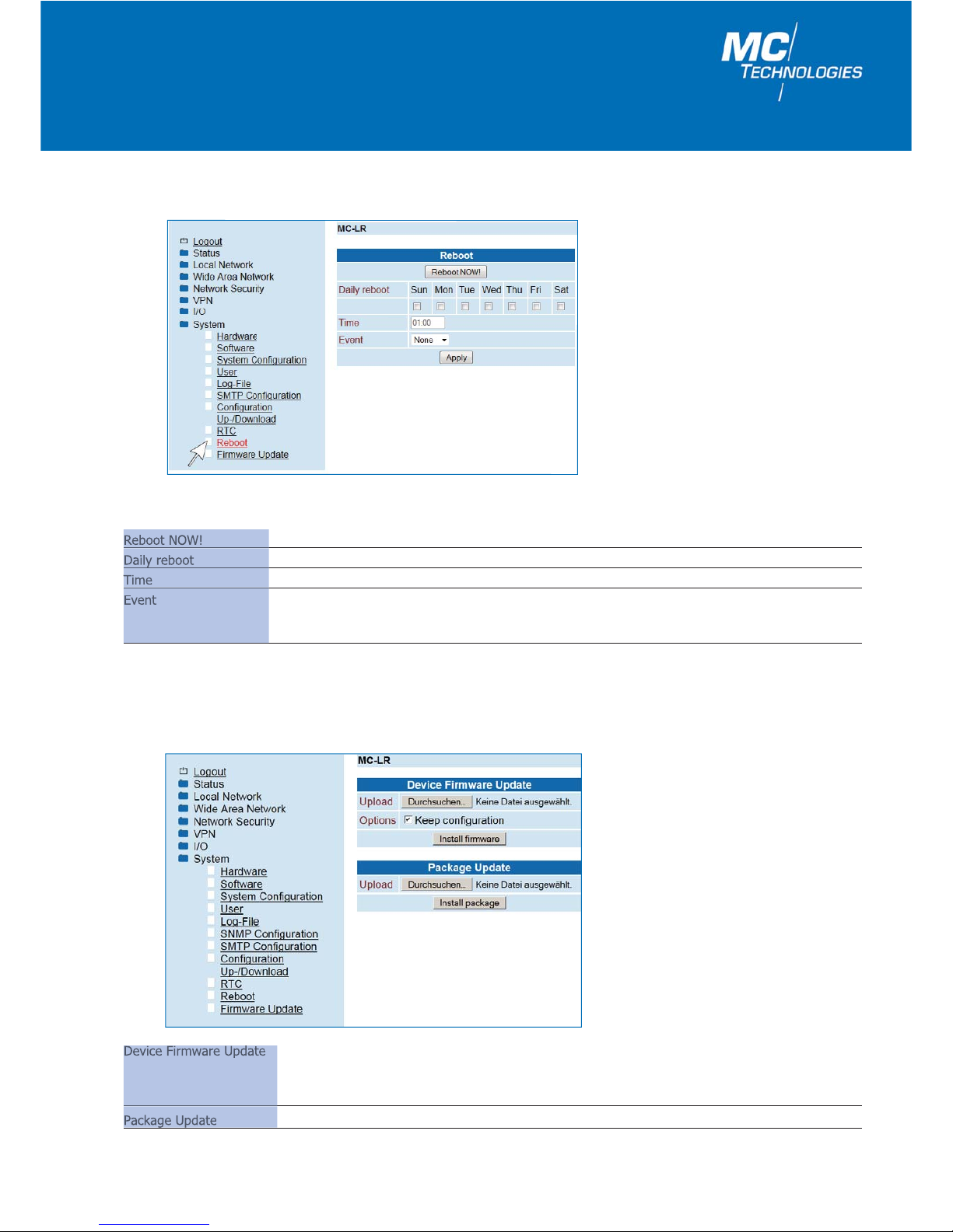
1.9.11 Firmware Update
1.9.10 Reboot - restarting the router
Reboot
Reboot NOW! Router immediately shut down and then restarted.
Daily reboot Set the day of the week for a reboot.
Time Enter time of reboot in the format: Hour: Minute.
Event
Input1: A restart can be triggered via a HIGH signal to the switching input I/O IN. Please ensure
that the switching input is ultimately set back to LOW to prevent another restart.
None: No event for a reboot.
Device Firmware Update Upload: Allows you to upload the latest firmware to the router.
Options: Select "Keep configuration" if your current configuration should be retained following a
firmware update or remove the tick if the configuration should be reset to factory
defaults.
Package Update Upload: Allows you to upload the latest Web interface to the router.

MC Technologies GmbH
44
2. 2. Additional functions
2.1 Router configuration using SSH and XML file
The router can be configured using the SSH protocol via the local Ethernet interface or in remote operation.
SSH or Secure Shell refers to both a network protocol and a corresponding programme which allows an encrypted net-
work connection to be generated using a remote device.
In Linux, use console input. In Windows, we recommend using the programs plink.exe and pscp.exe, which can
be downloaded at putty.org.
The examples below are based on the router default settings:
Username: admin
Password: admin
Router IP-Address: 192.168.0.1
2.1.1 Download configuration via SSH
You can download the router configuration as an XML file or as a TGZ file.
For Linux:
ssh admin@192.168.0.1 'su -c "/usr/sbin/export_cfg"' > config.xml
oder
ssh admin@192.168.0.1 'su -c "/usr/sbin/export_cfg tgz"' > config.tgz
For Windows with PLINK.EXE
plink -2 -pw admin admin@192.168.0.1 "su -c \"/usr/sbin/export_cfg\"" > config.xml
oder
plink -2 -pw admin admin@192.168.0.1 "su -c \"/usr/sbin/export_cfg tgz\"" > config.tgz
2.1.2 Upload configuration via SSH
For Linux:
a. a. Without router reboot:
cat config.xml | ssh admin@192.168.0.1 'su -c "/usr/sbin/store_cfg"'
b. b. With subsequent router reboot:
cat config.xml | ssh admin@192.168.0.1 'su -c "/usr/sbin/store_cfg; /sbin/reboot"'
The password is requested interactively by SSH. An automatic batch operation is not possible. You can, however, use
the "sshpass" programme to run a script file comprising the password. The script file (for example, cfgupl.sh) must
contain the following:
#!/bin/bash cat config.xml | ssh admin@192.168.0.1 'su -c "/usr/sbin/store_cfg; /sbin/reboot"'
The Linux command is as follows:
sshpass -padmin ./cfgupl.sh
For Windows with PSCP.EXE and PLINK.EXE
a. Without router-reboot:
pscp -scp -pw admin config.xml admin@192.168.0.1:/tmp/cfg.xml
plink -2 -pw admin admin@192.168.0.1 "su -c \"/usr/sbin/store_cfg /tmp/cfg.xml\""
b. With subsequent router reboot:
pscp -scp -pw admin config.xml admin@192.168.0.1:/tmp/cfg.xml
plink -2 -pw admin admin@192.168.0.1 "su -c \"/usr/sbin/store_cfg /tmp/cfg.xml; /sbin/reboot\""

User Manual/Web Interface MC-LR/MC-LR-4/MC-LRS/MC-LRS-4 – 01/2018 (FW 2.07.3)
45
2.2 Sending and receiving IO status, email and router status
using XML files via the router socket server
The router includes an integrated socket server and can do the following by receiving XML files:
1. Set and query I/O signals
2. Send messages such as email
3. Query router status
To use these functions, the socket server must be set to "Enabled" as described under 1.8.4 (Page 34).
The socket server port can be freely configured, the default setting is port = 1432.
2.2.1 Sample for XML files
The following are a few examples of XML file content:
Example: Setting and querying the I/O signals
<?xml version="1.0"?>
<io>
<output no="1" value="1"/>
<input no="1"/>
</io>
Example: Sending an email
<?xml version="1.0"?>
<email to=name1@domain.de cc="name2@domain.de">
<subject>Test Mail</subject>
<body>Dies ist ein E-Mail-Text.
</body>
</email>
Example: Querying router status
<?xml version="1.0"?>
<info>
<device />
<radio />
<ipsec />
<openvpn />
</info>

MC Technologies GmbH
46
2.2.2 Functions test using Windows HyperTerminal
For a test in Windows, the programme "HyperTerminal" can be used. Hyperterminal can be used to send XML files to
the router socket server. The corresponding (XML) files (see 2.2.1) must first be stored on your user PC.
Open Hyperterminal and configure the desired connection. (The example given uses the default settings):
Host address: 192.168.0.1 (Router / Socket Server IP-Address)
Connection number: 1432 (Socket Server Port)
Establish connection via: TCP/IP (Winsock)
Open the connection.
In the HyperTerminal menu "Transfer/send text file....", select the XML file to be transferred.
After transfer is complete, HyperTerminal displays the answer to your query.

User Manual/Web Interface MC-LR/MC-LR-4/MC-LRS/MC-LRS-4 – 01/2018 (FW 2.07.3)
47

MC Technologies GmbH
Kabelkamp 2
30179 Hannover, Germany
Tel.: +49 511 67 69 99 - 0
Direct: +49 511 67 69 99 - 128
Fax: +49 511 67 69 99 - 150
Web & Shop: www.mc-technologies.net
E-Mail: router@mc-technologies.net
We accept no liability for errors or misprints. We reserve the right to make technical alterations at any time. 01/2018
Company profile
We are a leading European provider of
innovative solutions for:
● Machine-to-machine (M2M) hardware and
end-to-end solutions
● GSM/GPRS/UMTS/HSPA+/LTE/GPS modules,
terminals, router and industrial computers
● Short range modules
● Customer-specific cable assemblies
● Connectors for industry
Thanks to our many years of experience we
can offer:
● A wide, competitively priced product range based
on German quality standards
● Design and development of the optimum solution
specifically tailored to your application
● Competent technical advice for product selection
and design-in
● Quick, professional implementation of all
accompanying commercial and logistical
processes
● Comprehensive service concepts for our
products and solutions
 Loading...