

Page 1
Operating Instructions
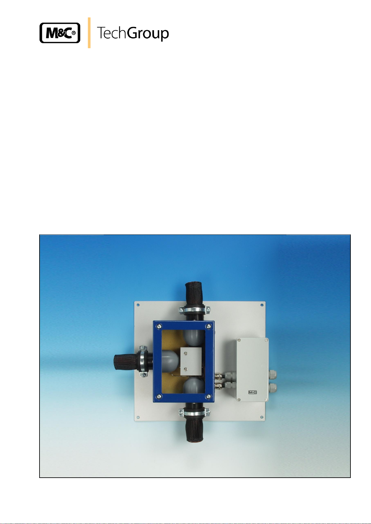
Electrically heated connectors
series T.-H1, V.-H1
Gas sampling and gas conditioning technology 6-6.1-ME
Page 2

2
Contents
1 General information ...................................................................................................................... 4
2 Declaration of conformity ............................................................................................................ 4
3 Safety instructions ....................................................................................................................... 4
4 Warranty ........................................................................................................................................ 5
5 Used terms and signal indications ............................................................................................. 5
6 Introduction and application ....................................................................................................... 7
6.1 Power supply ........................................................................................................................... 7
7 Technical Data .............................................................................................................................. 8
8 Description .................................................................................................................................... 8
9 Reception and storage ................................................................................................................. 9
10 Preparation and Installation ........................................................................................................ 9
11 Mounting ...................................................................................................................................... 10
12 Electrical Connection ................................................................................................................. 11
13 Starting ........................................................................................................................................ 12
14 Maintenance ................................................................................................................................ 13
15 Spare parts list ............................................................................................................................ 13
16 Appendix ..................................................................................................................................... 13
List of illustrations
Figure 1 Heated T-connector ............................................................................................................ 9
Figure 2 Heated connector .............................................................................................................. 10
Figure 3 Electrical connection ......................................................................................................... 11
Gas sampling and gas conditioning technology 6-6.1-ME
Page 3

3
This Operating Manual does not claim completeness and may be
subject to technical modifications.
© 04/2009 M&C TechGroup Germany GmbH. Reproduction of this
document or its content is not allowed without permission from M&C.
1st Edition: 04/2009
Dear customer,
we have made up this operating manual in such a way that all necessary information about the
product can be found and understood quickly and easily.
Should you still have any question, please do not hesitate to contact M&C directly or go through your
appointed dealer. Respective contact addresses are to be found in the annexe to this operating
manual.
Please also contact our homepage www.mc-techgroup.com for further information about our
products. There, you can read or download the data sheets and operating manuals of all M&C
products as well as further information in German, English and French.
Gas sampling and gas conditioning technology 6-6.1-ME
Page 4

4
Head Office
M&C TechGroup Germany GmbH Rehhecke 79 40885 Ratingen Germany
Telephone: 02102 / 935 - 0
Fax: 02102 / 935 - 111
E - mail: info@mc-techgroup.com
www.mc-techgroup.com
1 GENERAL INFORMATION
The product described in this operating manual has been examined before delivery and left our works
in perfect condition related to safety regulations. In order to keep this condition and to guarantee a
safe operation, it is important to heed the notes and prescriptions made in this operating manual.
Furthermore, attention must be paid to appropriate transportation, correct storage, as well as
professional installation and maintenance work.
All necessary information a skilled staff will need for appropriate use of this product are given in this
operating manual.
2 DECLARATION OF CONFORMITY
CE - Certification
The product described in this operating manual complies with the following EC directives:
EMV-Instruction
The requirements of the EC directive 2004/108/EC “Electromagnetic compatibility“ are met.
Low Voltage Directive
The requirement of the EC directive 2006/95/EC “Low Voltage Directive“ are met.
The compliance with this EC directive has been examined according to DIN EN 61010.
Declaration of conformity
The EU Declaration of conformity can be downloaded from the M&C homepage or directly requested
from M&C.
3 SAFETY INSTRUCTIONS
Gas sampling and gas conditioning technology 6-6.1-ME
Page 5

5
Please take care of the following basic safety procedures when mounting, starting up or
operating this equipment:
Read this operating manual before starting up and use of the equipment. The information and
warnings given in this operating manual must be heeded.
Any work on electrical equipment is only to be carried out by trained specialists as per the regulations
currently in force.
Attention must be paid to the requirements of VDE 0100 (IEC 364) when setting high-power electrical
units with nominal voltages of up to 1000 V, together with the associated standards and stipulations.
Check the details on the type plate to ensure that the equipment is connected to the correct mains
voltage.
Protection against touching dangerously high electrical voltages:
Before opening the equipment, it must be switched off and hold no voltages. This also applies to any
external control circuits that are connected.
The device is only to be used within the permitted range of temperatures and pressures.
Check that the location is weather-protected. It should not be subject to either direct rain or moisture.
The device must not be used in hazardous areas.
Installation, maintenance, monitoring and any repairs may only be done by authorized personnel with
respect to the relevant stipulations.
4 WARRANTY
If the equipment fails, please contact M&C directly or else go through your M&C authorised dealer.
We offer a one year warranty as of the day of delivery as per our normal terms and conditions of sale,
and assuming technically correct operation of the unit. Consumables are hereby excluded. The terms
of the warranty cover repair at the factory at no cost or the replacement at no cost of the equipment
free ex user location. Reshipments must be send in a sufficient and proper protective packaging.
5 USED TERMS AND SIGNAL INDICATIONS
Gas sampling and gas conditioning technology 6-6.1-ME
Page 6

6
DANGER!
This means that death, severe physical injuries and/or important
material damages will occur in case the respective safety measures
are not fulfilled.
W ARN IN G !
This means that death, severe physical injuries and/or important
material damages may occur in case the respective safety
measures are not fulfilled.
CARE!
This means that minor physical injuries may occur in case the
respective safety measures are not fulfilled.
CAR E!
Without the warning triangle means that a material damage may
occur in case the respective safety measures are not met.
ATT ENT ION !
This means that an unintentional situation or an unintentional status
may occur in case the respective note is not respected.
NOTE!
These are important information about the product or parts of the
operating manual which require user’s attention.
SKILLED STAFF
These are persons with necessary qualification who are familiar with
installation, use and maintenance of the product.
Gas sampling and gas conditioning technology 6-6.1-ME
Page 7

7
6 INTRODUCTION AND APPLICATION
In analysis technique, often temperatures must be kept above the sample gas dew point. Therefore, it
is absolutely necessary to avoid cold bridges.
In order to ensure this, the temperature regulated M&C hose-/tube connectors T..-H1 and V..-H1 are
used to connect heated sample lines type 3/4/5-N/M/H with an operating temperature up to 180 °C.
6.1 POWER SUPPLY
The electrically heated connectors T.-H1 and V.-H1 are available in 2 versions for alternating current
230V, 50Hz or 115V, 60Hz.
Gas sampling and gas conditioning technology 6-6.1-ME
Page 8

7 TECHNICAL DATA
T6-H1
T8-H1
V6-H1
V8-H1
Part number
10B1001 (a)**
10B1101 (a)**
10B1011 (a)**
10B1111 (a)**
3x ø 6 mm
3x ø 8 mm
2x ø 6 mm
2x ø 8 mm
max. 200 bar
max. +180 °C
-25 to +60 °C
-25 to +80 °C
Temperaturregler
capillary thermostat with high temperature limiter and low temperature alarm
230V 50Hz, 100VA **optionally 115V 60Hz (a)
IP 54 EN60529
EN 61010, EN60519-1
350 x 320 x 120 mm (w x h x d)
4,5 kg
8
8 DESCRIPTION
The M&C hose-/tube connectors T.-H1 and V.-H1 are fixed on a mounting plate, decoupled from heat
and covered with an insulated enclosure.
The heater consists of a heating element with high capacity. The temperature is adjustable on the
integrated thermostat up to 180 °C with high temperature limiter and low temperature alarm. The
connection box with integrated thermostat is installed outside the enclosure on the mounting plate.
The bushings for the heated sample lines in the enclosure are insulated with sockets of heat resistant
silicone. In order to avoid cold bridges, the connector is completely heated by means of a doubleended thermal conducting jaw. For fixing the electrically heated sample lines type 3/4/5-N/M/H – see
data sheet -2-6.1 –, mounting brackets are integrated.
Gas sampling and gas conditioning technology 6-6.1-ME
Page 9

9
NOTE!
The equipment should be stored in a protected, frost-free room!
9 RECEPTION AND STORAGE
Please take the heated connector and possible special accessories carefully out of the packaging
material immediately after arrival, and compare the goods with the items listed on the delivery note!
Check the goods for any damage caused during delivery and, if necessary, notify your transport
insurance company without delay of any damage discovered
The heated connector usually is delivered in one packaging unit.
10 PREPARATION AND INSTALLATION
Locate the heated connector in such a way that there is adequate space for removing the cover.
Make certain that the heated connector is easily accessible so that you can carry out any subsequent
repair work without trouble.
The aluminium plate is fixed with 4 screws.
Figure 1 Heated T-connector
Gas sampling and gas conditioning technology 6-6.1-ME
Page 10

10
HINWEIS!
If a PTFE tube is used as sample line, an insert must under all
circumstances be inserted in the end of the tube in order to prevent the
tube being pressed together.
Make sure that the connection is leak proof!
Figure 2 Heated connector
11 MOUNTING
For mounting the heated connector we recommend the following procedure:
Remove the lid of the heated connector by loosening the 4 screws;
Remove the thermal conductivity jaws by loosening the 2 screws M4;
Remove the upper part of the mounting clamp;
Put the heated sample line into the silicone cap and feed the end oft he tube through the hole
oft he cap;
Remove nut and compression rings of the fitting and put them in right order on the end of the
tube;
Put the end of the tube into the fitting;
The temperature-resistant, stainless steel connectors supplied by M&C have a double ferrule
system to ensure reliable sealing. After tightening the nuts of these connectors by hand, they
should then be tightened exactly 1¼ of a turn using a flat spanner and are then properly
mounted;
Retrofit the upper part of the mounting clamp;
After connection of the heated sample lines retrofit the thermal conductivity jaws and the lid;
Gas sampling and gas conditioning technology 6-6.1-ME
Page 11

11
W ARN IN G !
When connecting the equipment, please ensure that the supply
voltage is identical with the information provided on the model type
plate.
After mounting the heated connector, the posssibility of getting in
touch with live parts has to be prevented!
The use of temperature resistant cable is necessary !
NOTE!
Attention must be paid to the requirements of IEC 364 (DIN VDE
0100) when setting high-power electrical units with nominal
voltages of up to 1000 V, together with the associated standards
and stipulations.
A main switch and matching fuse must be provided externally!
The main circuit must be equipped with a fuse corresponding to
the nominal current (over current protection), for electrical details
see technical data.
12 ELECTRICAL CONNECTION
Remove the lid of the electrical connection box. The electrical connection layout is located in
the lid.
Insert the mains cable (min. 3 x 1.5 mm²) through the cable gland and connect to the
appropriate terminals (Fig.3).
Insert the signal cable through the cable gland and connect to the appropriate terminals.
Screw lid back on.
Figure 3 Electrical connection
Gas sampling and gas conditioning technology 6-6.1-ME
Page 12

12
W ARN IN G !
Before starting up check whether the mains power supply voltage
corresponds with the information stated on the nameplate.
Beware of touching the filter surface during operation. Serious
burns can occur because of high surface temperatures. Wear
protective gloves and protect the filter from unauthorized access.
NOTE!
If the rated value temperature needs to be lowered more than 30°C
in one step during operation, the thermostat's excess temperature
switch-off is triggered (for re-start press reset key).
NOTE!
The total heating-up time is approximately 30 minutes. After
exceeding the low temperature limit (30°C below set temperature)
the connector is ready for operation.
In case of low temperature alarm (failure of heating) the gas flow
has to be interrupted by adequate measures!
13 STARTING
Before using the equipment for the first time, check that the safety measures specific to the installation
and process are complied with!
For the carried media the corresponding safety regulations and measures have to be considered.
The following procedure is recommended:
Check the rated value setting on the built-in thermostat.
Switch on mains power supply.
Gas sampling and gas conditioning technology 6-6.1-ME
Page 13
13
W ARN IN G !
Aggressive condensate is possible.
Wear protective glasses and proper protective clothing!
High surface temperatures!
Touching the filter surface can cause serious burns!
Wear protective gloves and protect the filter of unauthorized
access!
Prior to carrying out maintenance work on electrical parts, mains
voltage should be disconnected from all poles!
This also applies to any external control circuits, which may be
connected.
Electrically heated connectors T.-H1 and V.-H1
(C) Consumables, (R) recommended spare parts, and
(S) spare parts
Recommended quantity
For operating period
[years]
C/R/S
1 2 3
90 P 5015
Heating cartridge , 230V/50Hz, 100W, length: 50mm
S
a.t.r.
a.t.r.
a.t.r.
90 P 5016
Heating cartridge , 115V/60Hz, 100W, length: 50mm
S
a.t.r.
a.t.r.
a.t.r.
90 P 5020
Thermostat (0-180°C), with over-temperature limiter
and low-temperature alarm
S
a.t.r.
a.t.r.
a.t.r.
14 MAINTENANCE
In case of correct use the heated connector works maintenance free.
The safety instructions specific to the plant and process are to be consulted prior to any repair work!
15 SPARE PARTS LIST
a.t.r. = according to requirements
16 APPENDIX
Further product documentation can be seen and downloaded from our homepage:
Gas sampling and gas conditioning technology 6-6.1-ME
www.mc-techgroup.com
 Loading...