

Page 1
Operating Manual
Gas sampling and gas conditioning technology 3-0.1-ME
Page 2

2
This Operating Manual does not claim completeness and may be
subject to technical modifications.
© 10/2009 M&C TechGroup Germany GmbH. Reproduction of this
document or its content is not allowed without permission from M&C.
1st Edition: 01/2010
Dear customer,
we have made up this operating manual in such a way that all necessary information about the
product can be found and understood quickly and easily.
Should you still have any question, please do not hesitate to contact M&C directly or go through your
appointed dealer. Respective contact addresses are to be found in the annexe to this operating
manual.
Please also contact our homepage www.mc-techgroup.com for further information about our
products. There, you can read or download the data sheets and operating manuals of all M&C
products as well as further information in German, English and French.
Gas sampling and gas conditioning technology 3-0.1-ME
Page 3

3
Content
1 General information ................................................................................................................... 4
2 Declaration of conformity ......................................................................................................... 4
3 Safety instructions ..................................................................................................................... 5
4 Warranty ..................................................................................................................................... 5
5 Used terms and signal indications ........................................................................................... 6
6 Introduction ................................................................................................................................ 7
7 Application ................................................................................................................................. 7
8 Technical Data ............................................................................................................................ 7
9 Description ................................................................................................................................. 8
10 Function .................................................................................................................................... 10
11 Reception and storage ............................................................................................................ 11
12 Installation instructions .......................................................................................................... 12
13 Supply connections ................................................................................................................. 12
13.1 Hose connections ................................................................................................................... 12
13.2 Electrical connections ............................................................................................................. 13
14 Start-up ..................................................................................................................................... 14
15 Closing down ........................................................................................................................... 14
16 Maintenance ............................................................................................................................. 14
16.1 Cleaning the cooling fins ......................................................................................................... 14
16.2 Maintenance of the peristaltic pump(s), type SR25.1 and SR25.2 ......................................... 15
16.2.1 Change of the pump tube ................................................................................................ 15
16.2.2 Change of contact pulleys and springs ............................................................................ 16
16.2.3 Cleaning the pump head ................................................................................................. 16
17 Spare parts list ......................................................................................................................... 17
18 Appendix ................................................................................................................................... 18
List of illustrations
Figure 1 Dimensions VC-1 ............................................................................................................... 8
Figure 2 Dimensions VC-1-SL ......................................................................................................... 9
Figure 3 Dimensions VC-2-L ........................................................................................................... 9
Figure 4 Dimensions VC-2-SL ....................................................................................................... 10
Figure 5 Schematic diagram of the heat exchanger function ........................................................ 11
Figure 6 Electrical connection VC-1-SL ......................................................................................... 13
Figure 7 Electrical connection VC-2-SL ......................................................................................... 13
Figure 8 Change of the pump tube ................................................................................................ 15
Gas sampling and gas conditioning technology 3-0.1-ME
Page 4

4
Head Office
M&C TechGroup Germany GmbH Rehhecke 79 40885 Ratingen Germany
Telephone: 02102 / 935 - 0
Fax: 02102 / 935 - 111
E - mail: info@mc-techgroup.com
www.mc-techgroup.com
1 GENERAL INFORMATION
The product described in this operating manual has been examined before delivery and left our works
in perfect condition related to safety regulations. In order to keep this condition and to guarantee a
safe operation, it is important to heed the notes and prescriptions made in this operating manual.
Furthermore, attention must be paid to appropriate transportation, correct storage, as well as
professional installation and maintenance work.
All necessary information a skilled staff will need for appropriate use of this product are given in this
operating manual.
2 DECLARATION OF CONFORMITY
CE - Certification
The product described in this operating manual complies with the following EC directives:
EMV-Instruction
The requirements of the EC directive 2004/108/EC “Electromagnetic compatibility“ are met.
Low Voltage Directive
The requirement of the EC directive 2006/95/EC “Low Voltage Directive“ are met.
The compliance with this EC directive has been examined according to DIN EN 61010.
Declaration of conformity
The EU Declaration of conformity can be downloaded from the M&C homepage or directly requested
from M&C.
Gas sampling and gas conditioning technology 3-0.1-ME
Page 5

5
3 SAFETY INSTRUCTIONS
Please take care of the following basic safety procedures when mounting, starting up or
operating this equipment:
Read this operating manual before starting up and use of the equipment. The information and
warnings given in this operating manual must be heeded.
Any work on electrical equipment is only to be carried out by trained specialists as per the regulations
currently in force.
Attention must be paid to the requirements of VDE 0100 (IEC 364) when setting high-power electrical
units with nominal voltages of up to 1000 V, together with the associated standards and stipulations.
Check the details on the type plate to ensure that the equipment is connected to the correct mains
voltage.
Protection against touching dangerously high electrical voltages:
Before opening the equipment, it must be switched off and hold no voltages. This also applies to any
external control circuits that are connected.
The device is only to be used within the permitted range of temperatures and pressures.
Check that the location is weather-protected. It should not be subject to either direct rain or moisture.
The devices must not be used in hazardous areas.
Installation, maintenance, monitoring and any repairs may only be done by authorized personnel with
respect to the relevant stipulations.
4 WARRANTY
If the equipment fails, please contact M&C directly or else go through your M&C authorised dealer.
We offer a one year warranty as of the day of delivery as per our normal terms and conditions of sale,
and assuming technically correct operation of the unit. Consumables are hereby excluded. The terms
of the warranty cover repair at the factory at no cost or the replacement at no cost of the equipment
free ex user location. Reshipments must be send in a sufficient and proper protective packaging.
Gas sampling and gas conditioning technology 3-0.1-ME
Page 6
6
DANGER!
This means that death, severe physical injuries and/or important
material damages will occur in case the respective safety measures
are not fulfilled.
W ARN IN G !
This means that death, severe physical injuries and/or important
material damages may occur in case the respective safety
measures are not fulfilled.
CARE!
This means that minor physical injuries may occur in case the
respective safety measures are not fulfilled.
CAR E!
Without the warning triangle means that a material damage may
occur in case the respective safety measures are not met.
ATT ENT ION !
This means that an unintentional situation or an unintentional status
may occur in case the respective note is not respected.
NOTE!
These are important information about the product or parts of the
operating manual which require user’s attention.
SKILLED STAFF
These are persons with necessary qualification who are familiar with
installation, use and maintenance of the product.
5 USED TERMS AND SIGNAL INDICATIONS
Gas sampling and gas conditioning technology 3-0.1-ME
Page 7

7
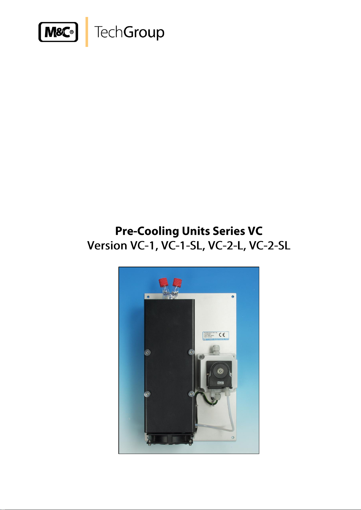
Pre-cooling unit version
VC-..
VC-1
VC-1-SL
VC-2-L
VC-2-SL
Part No. 230V 50-60Hz
03K1000
03K3000
03K4000
03K5000
Part No. 115V 50-60Hz
03K1000
03K3000a
03K4000a
03K5000a
Jet-Stream heat exchanger
out of Duran glass EC-G
1x
1x
2x
2x
Forced ventilation
no
yes
yes
yes
Autom. condensate
removal with SR25..
1x 2x
Sample gas connection
2x GL18-6
2x GL18-6
4x GL18-6
4x GL18-6
Condensate connection
1x GL25-12
1x DN4/6
2x GL25-12
2x DN4/6
Power consumption
25VA
20VA
30VA
Gas flow rate
recommended, (other flow
rates possible)
1x 250 Nl/h
1x 250 Nl/h
2x 250 Nl/h
2x 250 Nl/h
Weight approximately
ca. 3,5 kg
ca. 7,5 kg
ca. 9 kg
ca. 11 kg
Sample gas pressure
max. 3 bar g
ΔP per heat exchanger
4 mbar at 300 Nl/hr
Stagnant space per heat
exchanger
70 ml
Sample inlet temperature
max. 180 °C
Ambient temperature
+2 °C to +45 °C
Storage temperature
0 °C to +55 °C
Electrical connection
Terminals max. 2,5 mm2, PG11 cable gland
Electrical standard / Case
protection
EN 61010 / IP22-EN60529
Method of mounting /
Ready for working
mounting / immediately
Material of sample
contacting parts
Duran glass®,
PTFE
Duran glass®,
PTFE, PVDF,
Novoprene
Duran glass®,
PTFE
Duran glass®,
PTFE, PVDF,
Novoprene
6 INTRODUCTION
The VC-... pre-cooling units produced by M&C incorporates the “Jet-Stream’’ design of heat
exchanger. This design induces condensate formation and guarantees optimum dew point reduction to
ambient temperature.
7 APPLICATION
The M&C pre-cooling units VC-... are used in gas analysis to lower the dew point of humid gas, for
example:
• to relieve downstream main cooling system
• if process-bound water or steam irruption can become forward,
• if non-heated sample lines without adequate slope are mounted,
• for gas analysis system with electrochemical sensors.
8 TECHNICAL DATA
Gas sampling and gas conditioning technology 3-0.1-ME
Page 8

8
9 DESCRIPTION
The condensate formed should be removed with a small peristaltic pump, sample trap or collection
vessel. The VC-..-SL pre-cooling unit has as a standard peristaltic pumps SR25.1 for automatic
condensate removal. The VC-..-..L pre-cooling unit has got a fan to force the ventilation of the cooling
fins for performance rise. In this case, a deflector is integrated for an optimal air conduction. The
VC-1-.. pre-cooling unit is equipped with one EC-Jet-Stream heat exchanger. The VC-2-.. pre-cooling
unit is equipped with two EC-Jet-Stream heat exchangers to connect two independent sample streams
or parallel or series function to connect one sample stream with a corresponding high flow rate. The
compact lightweight design of this device makes it ideal for use in portable and continuous sample
conditioning systems. The pre-cooling units are self-controlling with low maintenance.
Figure 1 Dimensions VC-1
Gas sampling and gas conditioning technology 3-0.1-ME
Page 9

9
Figure 2 Dimensions VC-1-SL
Figure 3 Dimensions VC-2-L
Gas sampling and gas conditioning technology 3-0.1-ME
Page 10

10
Figure 4 Dimensions VC-2-SL
10 FUNCTION
The especially for gas analysis designed M&C gas pre-cooler type VC-.. cools sample gas down to
ambient temperature. The novel construction of the jet-stream heat exchangers guarantees a very
good pre-separation of condensate and for that reason an optimal drying of sample gas with a
minimum of washing out effects. Figure 3 shows the functional diagram of the heat exchanger.
Gas sampling and gas conditioning technology 3-0.1-ME
Page 11

11
+5°C
Sample
OUT
Sample
IN
Condensate OUT
Cooling
block
NOTE!
The cooler must be stored in a weather protected frost-free area!
Figure 5 Schematic diagram of the heat exchanger function
11 RECEPTION AND STORAGE
The gas cooler VC-.. are complete pre-installed units.
Carefully inspect the cooler and any special accessories included with it immediately on arrival
by removing them from the packing and checking for missing articles against the packing list !
Check the items for any damage in transit and, if required, inform the shipping insurance
company immediately of the damage found!
Gas sampling and gas conditioning technology 3-0.1-ME
Page 12

12
NOTE!
Unheated gas sample lines must be provided with slope up to the cooler.
Connect the heated sample line with sufficient thermal decoupling of min.
20cm to the cooler!
NOTE!
Do not mix up the hose connections; the inlet and outlet connections of
the heat exchangers are marked with arrows;
Ensure that the connections are sealed adequately;
To ensure free removal of the condensate, ensure that the listed
diameters for the condensate removal lines are not reduced!
12 INSTALLATION INSTRUCTIONS
The cooler VC-.. is suitable for wall mounting. Mounting dimensions see figure 1-4.
13 SUPPLY CONNECTIONS
13.1 HOSE CONNECTIONS
The connection for sample gas inlet and outlet happens at the GL-connectors on the upper part of the
heat exchangers. In standard a hose with 6mm outer diameter is connected. M&C tube resp. hose
connectors are available as option (see data sheet 3-5.1.1)
Ensure that the connections are sealed adequately by noting the following:
Before assembly, check the GL coupling rings to see if the PTFE/silicon locking rings have
been damaged.
The sealing rings should be installed with the PTFE side facing the medium.
The condensate connection for the VC-1-SL and VC-2-SL is done at the hose connectors DN4/6 of
the peristaltic pumps.
For VC-1 and VC-2L the connection is done at the bottom of the heat exchanger with the following
possibilities of condensate removal:
peristaltic pump(s) type SR25.1 or SR25.2-G (required connection adapter part no. 09F9520
for VC-1 resp. 05V6035 for VC-2L),
external mounted condensate vessel(s) with manually emptying (required connection adapter
part no. 09F9525 DN6/8 or 09F9530 DN10/12),
automatic float-type condensate traps type AD-... (only for excess pressure operation).
(required connection adapter part no. 09F9525 DN6/8 or 09F9530 DN10/12).
Gas sampling and gas conditioning technology 3-0.1-ME
Page 13

13
CARE!
When connecting the equipment, please ensure that the supply
voltage is identical with the information provided on the model type
plate!
NOTE!
Attention must be paid to the requirements of IEC 364 (DIN VDE
0100) when setting high-power electrical units with nominal
voltages of up to 1000V, together with the associated standards
and stipulations.
An external main switch must be provided.
The main circuit must be equipped with a fuse (over current
protection); for electrical details see technical data (chapter 8).
13.2 ELECTRICAL CONNECTIONS
The electrical connection of the VC-1-SL is done in the housing of the peristaltic pump SR25.2-G:
Figure 6 Electrical connection VC-1-SL
The electrical connection of the VC-2-L is done in the connection box at terminals:
L = 3, N = 2 and PE = 1
The electrical connection of the VC-2-SL is done in the housing of the 2 peristaltic pumps SR25.1:
Figure 7 Electrical connection VC-2-SL
Gas sampling and gas conditioning technology 3-0.1-ME
Page 14

14
NOTE!
The location for the cooler must remain frost-free, even when the unit has
been switched off!
If the cooler unit is putting out of action for a short time no particular
measures need to be taken.
We recommend sweeping the cooler with inert gas or ambient air while
the unit is putting out of action for a longer time.
CARE!
Aggressive condensate is possible.
Wear protective glasses and proper protective clothing!
DANGER!
Dangerous voltage!
It is necessary to take the gas cooler off the mains before any
assembly, maintenance and repair work is carried out!
14 START-UP
The following steps should be carried out before initial start-up:
Connect the cooler unit to the mains power supply (except VC-1); Check that the equipment is
connected to the correct mains voltage, 115V or 230V, as shown on the type plate.
15 CLOSING DOWN
16 MAINTENANCE
The safety instructions specific to the plant and process are to be consulted prior to any maintenance
work!
The cooler VC-.. does not require any special maintenance intervals.
16.1 CLEANING THE COOLING FINS
Dust on the cooling fins reduces the cooling capacity. Therefore it is necessary to clean the fins from
time to time. The following steps are recommended:
Disconnect the cooler from the mains (except VC-1);
Unscrew the cooler hood and remove it carefully (except VC-1);
Clean the fins carefully with compressed air;
Re-install the cooler hood;
Gas sampling and gas conditioning technology 3-0.1-ME
Page 15

15
DANGER
Dangerous voltage !
It is necessary to take the pump off the mains before any assembly,
maintenance and repair work is carried out !
CARE!
Aggressive condensate is possible !
Wear protective glasses and proper protective clothing !
NOTE!
If you send back the peristaltic pump to the M&C service for repair,
please let us know what kind of condensate has been pumped.
Before sending the pump back clean all parts from dangerous or highly
aggressive contaminants.
1
2
3
4
16.2 MAINTENANCE OF THE PERISTALTIC PUMP(S), TYPE SR25.1 AND SR25.2
Before the maintenance work is carried out, it is necessary that the specific safety procedures
pertaining to the system and operational process are observed !
Flexible tube, conveying belt, contact pulleys and contact springs are the only parts of the pump
subject to wear. They are simple to change.
16.2.1 CHANGE OF THE PUMP TUBE
Figure 8 Change of the pump tube
Take off the cooler of the mains;
Open hose connectors at the pump;
Press conveying belt at the recessed grips and turn S-bolt clockwise up to limit stop;
Gas sampling and gas conditioning technology 3-0.1-ME
Page 16

16
NOTE!
Only the usage of the original hose set guarantees a perfect function.
Never lubricate the hose.
Before mounting the pump check all parts for impurity and clean if
necessary.
NOTE!
While mounting pay attention to the fit of ‘rotational axis driver’.
Use genuine M&C spare parts only!
CARE!
Aggressive sample is possible!
Wear protective glasses and proper protective clothing
during disassembly, repair or cleaning!
Take away conveying belt and remove the old hose set from the guides by the hose
connectors;
Press the two contact pulleys and check whether the spring pressure is still sufficient, if not,
the contact springs have to be changed (see 16.2.2);
Put the new hose set with the hose connectors into the guides of the conveying belt ;
Put the conveying belt with the new hose into the dovetail guide of the pump body;
Press conveying belt at the recessed grips and simultaneously turn the S-bolt anticlockwise
until it snaps;
Switch on pump.
16.2.2 CHANGE OF CONTACT PULLEYS AND SPRINGS
Take off the cooler of the mains;
Unscrew the nut of the pump head (span of the jaw 5,5);
Draw the pump head out of the motor shaft; Now the driver can picked out of the pump head
and is ready for maintenance.
The removal of the springs (4 pcs.) away from the driver is possible without the aid of any
tools. Therefore press together the spring and take it out of the groove in the driver respectively
out of the boring in the axle. Now the roller bearing axle can be dismounted and the contact
pullets are ready for change.
Remounting happens in the opposite way.
16.2.3 CLEANING THE PUMP HEAD
When changing flexible tube or other parts, inspect all parts for dirt before assembling the
pump head and clean them if necessary.
As far as possible clean the parts with a dry cloth. Solvents should not be used as they can
attack the plastics and synthetic rubber parts. If a compressed air line is available, blow the
parts out with it.
Gas sampling and gas conditioning technology 3-0.1-ME
Page 17

17
Electric gas cooler VC-..
(C) Consumable parts
(R) Recommended spare parts
(S) Spare parts
Recommended quantity being in
operation [years]
Part No.
Indication
C/R/S
1 2 3
02 K 9100
Jet-stream heat exchanger type EC-G. Material: Duran-glass.
Connections: Sample gas: 2x GL18-6mm, Condensate: 1x
GL25-12mm
R 1 1 1
90 K 0115
Thermal conductivity paste, -20 to +140°C, silicon free, 50gr.
R 1 1
2
90 K 0035
ECP, EC-FD fan 230V 50Hz.
C - -
1
91 F 1010
Sealing ring GL18-6mm, material: PTFE.
R 2 4
6
91 F 1015
Sealing ring GL18-8mm, material: PTFE.
R 2 4
6
91 F 0025
Sealing ring GL25-12mm, material: PTFE.
R 2 4
6
91 F 1005
Spare union nut GL18
R 1 1
1
91 F 1007
Spare union nut GL18/14
R 1 1
1
90 F 0020
Spare union nut GL 25
R 1 1
1
90 F 0022
Spare union nut GL 25/18
R 1 1
1
09 F 9500
Connector/adaptor GL18 DN4/6 PV
S - -
-
09 F 9520
Connector/adaptor GL25 DN4/6 PV.
S - -
-
09 F 9525
Connector/adaptor GL 25 DN6/8 PV
S - -
-
09 F 9530
Connector/adaptor GL 25 DN10/12 PV
S - -
-
Peristaltic pump SR25.1 and SR25.2
(C) Consumable parts
(R) Recommended spare parts
(S) Spare parts
Recommended quantity being in
operation [years]
Part No.
Indication
C/R/S
1 2 3
90 P 1007
Hose set SR25.1
with PVDF-tube connectors 4/6mm, standard
C 1 2
4
90 P 1020
Driver SR25, complete
S - 1
1
90 P 1010
1 set (4 pcs) contact springs SR25 for driver
R 1 2 2 90 P 1045
Contact pulleys SR25 PVDF for driver
S 2 4 4 90 P 1050
Conveying belt SR25.1
S - 1
2
90 P 1025
S-bolt SR25.1
S - - 1 01 P 1000
Peristaltic pump SR25.1, complete 230V/115V, 50/60Hz
R - -
1
01 P 1300
Peristaltic pump SR25.2, complete 230V/115V, 50/60Hz
R - - 1 90 P 1030
Heat peristaltic pump SR25, complete without motor and gears
S - -
1
17 SPARE PARTS LIST
Wear, tear and replacement part requirements depend on specific operating conditions.
The recommended quantities are based on experience and they are not binding.
Gas sampling and gas conditioning technology 3-0.1-ME
Page 18

18
18 APPENDIX
Further product documentation can be seen and downloaded from our home page:
www.mc-techgroup.com
Threaded couplings for ”GL” glass connections
Document: 3-5.1.1
Instruction manual peristaltic pump SR25.1
Document: 3-7.1ME
Automatic liquid drain AD-SS
Document: 3-6.2.3
Automatic liquid drain AD-P
Document: 3-6.2.1
Condensate vessel TG, TK
Document: 3-6.3.1
Gas sampling and gas conditioning technology 3-0.1-ME
 Loading...