

Page 1

Operating Manual
Peristaltic pump series SR®
version SR25.1, SR25.2-G, SR25.1/Ex
Gas sampling and gas conditioning technology 3-7.1-ME
Page 2

Dear customer,
we have made up this operating manual in such a way that all necessary information about the
product can be found and understood quickly and easily.
Should you still have any question, please do not hesitate to contact M&C directly or go through your
appointed dealer. Respective contact addresses are to be found in the annexe to this operating
manual.
Please also contact our homepage www.mc-techgroup.com for further information about our
products. There, you can read or download the data sheets and operating manuals of all M&C
products as well as further information in German, English and French.
This Operating Manual does not claim completeness and may be
subject to technical modifications.
© 01/2001 M&C TechGroup Germany GmbH. Reproduction of this
document or its content is not allowed without permission from M&C.
®
is a registered trade mark.
SR
7th Edition: 04/2013
2
Gas sampling and gas conditioning technology 3-7.1-ME
Page 3

Content
1 General information .................................................................................................................... 4
2 Declaration of conformity .......................................................................................................... 4
3 Safety instructions ..................................................................................................................... 5
4 Warranty ...................................................................................................................................... 5
5 Used terms and signal indications ........................................................................................... 6
6 Introduction ................................................................................................................................. 7
7 Technical Data ............................................................................................................................ 7
8 Description .................................................................................................................................. 8
9 Reception and storage ............................................................................................................. 10
10 Installation instructions ........................................................................................................... 10
11 Supply connections .................................................................................................................. 11
11.1 Hose connections ................................................................................................................ 11
11.2 Electrical connections ........................................................................................................ .. 12
12 Start-up ...................................................................................................................................... 13
13 Closing down ............................................................................................................................ 13
14 Maintenance .............................................................................................................................. 14
14.1 Change of the pump tube .................................................................................................... 14
14.2 Change of contact pulleys and springs ................................................................................ 15
14.2.1 Cleaning the pump head .............................................................................................. 17
15 Repair information .................................................................................................................... 17
16 Spare parts list ..............................................................................................................
............ 17
17 Appendix ................................................................................................................................... 18
List of illustrations
Figure 1 Universal unit EC-FD with built in peristaltic pumps SR25.1 ............................................. 8
Figure 2 Dimensions SR25.1 ........................................................................................................... 9
Figure 3 Dimensions SR25.1/EX ..................................................................................................... 9
Figure 4 Dimensions SR25.2-G ..................................................................................................... 10
Figure 5 Connection of the distribution voltage ............................................................................. 12
Figure 6 Change of the pump tube ................................................................................................ 14
Figure 7 Disassembly of pump head and driver ............................................................................ 15
Figure 8 Check of axes and rolls ................................................................................................... 16
Figure 9 Spare part drawing SR25.1 ............................................................................................. 19
Figure 10 Spare part drawing SR25.2 ............................................................................................. 20
Figure 11 EC-type examination certificate SR25.1/EX, SR25.2/EX and SR25.3/EX ...................... 21
3-7.1-ME Gas sampling and gas conditioning technology 3
Page 4

Head Office
M&C TechGroup Germany GmbH Rehhecke 79 40885 Ratingen Germany
Telephone: 02102 / 935 - 0
Fax: 02102 / 935 - 111
E - mail: info@mc-techgroup.com
www.mc-techgroup.com
1
The product described in this operating manual has been examined before delivery and left our works
in perfect condition related to safety regulations. In order to keep this condition and to guarantee a
safe operation, it is important to heed the notes and prescriptions made in this operating manual.
Furthermore, attention must be paid to appropriate transportation, correct storage, as well as
professional installation and maintenance work.
All necessary information a skilled staff will need for appropriate use of this product are given in this
operating manual.
2
GENERAL INFORMATION
DECLARATION OF CONFORMITY
CE - Certification
The product described in this operating manual complies with the following EC directives:
EMV-Instruction
The requirements of the EC directive 2004/108/EC “Electromagnetic compatibility“ are met.
Low Voltage Directive
The requirement of the EC directive 2006/95/EC “Low Voltage Directive“ are met.
The compliance with this EC directive has been examined according to DIN EN 61010.
Declaration of conformity
The EU Declaration of conformity can be downloaded from the M&C homepage or directly requested
from M&C.
4
Gas sampling and gas conditioning technology 3-7.1-ME
Page 5

3 SAFETY INSTRUCTIONS
Please take care of the following basic safety procedures when mounting, starting up or
operating this equipment:
Read this operating manual before starting up and use of the equipment. The information and
warnings given in this operating manual must be heeded.
Any work on electrical equipment is only to be carried out by trained specialists as per the regulations
currently in force.
Attention must be paid to the requirements of VDE 0100 (IEC 364) when setting high-power electrical
units with nominal voltages of up to 1000 V, together with the associated standards and stipulations.
Check the details on the type plate to ensure that the equipment is connected to the correct mains
voltage.
Protection against touching dangerously high electrical voltages:
Before opening the equipment, it must be switched off and hold no voltages. This also applies to any
external control circuits that are connected.
The device is only to be used within the permitted range of temperatures and pressures.
Check that the location is weather-protected. It should not be subject to either direct rain or moisture.
The peristaltic pumps SR25.1 and SR25.2-G must not be used in hazardous areas.
Installation, maintenance, monitoring and any repairs may only be done by authorized personnel with
respect to the relevant stipulations.
4
WARRANTY
If the equipment fails, please contact M&C directly or else go through your M&C authorised dealer.
We offer a one year warranty as of the day of delivery as per our normal terms and conditions of sale,
and assuming technically correct operation of the unit. Consumables are hereby excluded. The terms
of the warranty cover repair at the factory at no cost or the replacement at no cost of the equipment
free ex user location. Reshipments must be send in a sufficient and proper protective packaging.
3-7.1-ME Gas sampling and gas conditioning technology 5
Page 6

5 USED TERMS AND SIGNAL INDICATIONS
This means that death, severe physical injuries and/or important
material damages will occur in case the respective safety measures
DANGER!
are not fulfilled.
This means that death, severe physical injuries and/or important
material damages may occur in case the respective safety
WARNING!
measures are not fulfilled.
This means that minor physical injuries may occur in case the
respective safety measures are not fulfilled.
CARE!
CARE!
Without the warning triangle means that a material damage may
occur in case the respective safety measures are not met.
ATTENTION!
This means that an unintentional situation or an unintentional status
may occur in case the respective note is not respected.
These are important information about the product or parts of the
operating manual which require user’s attention.
NOTE!
SKILLED STAFF
These are persons with necessary qualification who are familiar with
installation, use and maintenance of the product.
6
Gas sampling and gas conditioning technology 3-7.1-ME
Page 7
6 INTRODUCTION
The peristaltic pump SR25... has been specially developed for the condensate removal in analysis
applications. It ensures a continuous condensate discharge at gas sample coolers, condensate
collecting vessels, etc.
Synchronous motor and gearing unit with return stop make a condensate backflow impossible. The
capacity of 0,3l/hr guarantees a safe condensate removal, for example when cooling 850l/hr sample
gas with an inlet dew point of +70°C.
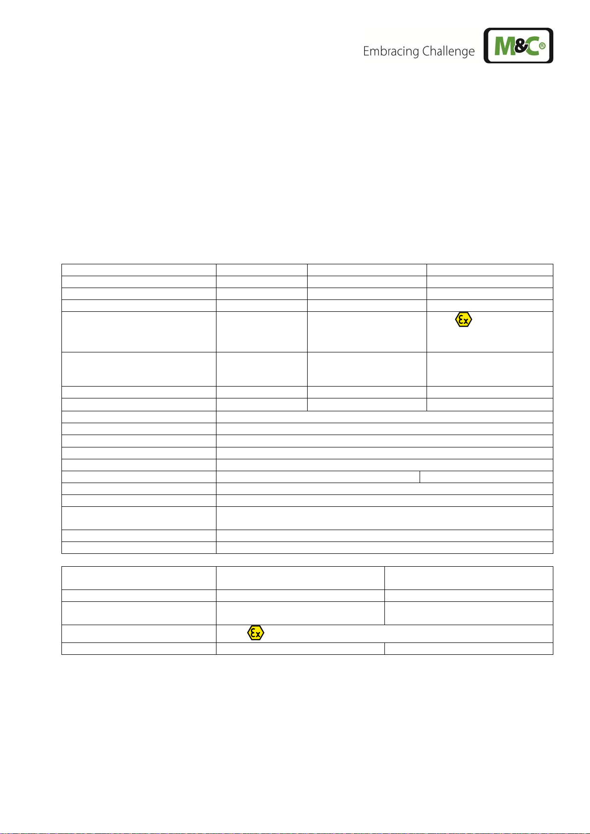
7
Peristaltic pump series SR25® version SR25.1 version SR25.2-G version SR25.1/Ex
Part No. 01 P 1000 01 P 1120 01 P 1201
Housing no yes, out of PVC no
Method of mounting boxed type wall mounting boxed type
Protection / electrical standard IP 10 EN60529 IP 52 EN60529
Electrical connection terminal 1,5 mm2 terminal 1,5 mm2
Dimensions (mm) 130x110x80 105x100x107 130x110x80
Weight (kg)
Peristaltic pump speed 5 rpm standard
Capacity 0,3 l/h standard
Suction max. 200 mbar abs.
Pressure max. 2200 mbar abs.
Sample temperature 0 °C - +60 °C
Ambient temperature 0 °C - +50 °C +5 °C - +50 °C
Storage temperature -10 °C - +60°C
Connections Tube connections DN 4/6 mm
Material of sample contacting
parts
Power supply / consumption 115/230V 50/60Hz, 3,5VA
Continuous duty 100 %
TECHNICAL DATA
IP40, II 2 G EEx m II
T5 certificate no. KEMA
03ATEX2218 X
600 mm cable 4 x 0,5mm2
1 x M20 x 1,5
0,6 0,8 0,7
PVDF, Novoprene
with screwed cable gland
M12 x 1,5
Option Ex-connecting box for
SR25.1/Ex
Part number 01P9400 01P9405
Electrical connections / cable
gland
Protection / electrical standard
Dimensions (mm) / Weight (kg) 75 x 80 x 55 / 0,35 160 x 75 x 55 / 0,6
Version for one peristaltic pump Version for 4 peristaltic pumps
terminals max. 4 x 2,5 mm2/ 1 x
M20x1,5, 1xM12x1,5
IP65, II 2 G EEx e II T5
terminals max. 16 x 2,5 mm2/ 1 x
M20x1,5, 4 x M12x1,5
3-7.1-ME Gas sampling and gas conditioning technology 7
Page 8

8 DESCRIPTION
The peristaltic pump SR25.1 is self-suctioning and designed for continuous operation. It consists of 3
compact parts:
synchronous motor,
gearing unit with return stop,
pump.
The slow speed (5rpm) of the two PVDF hose contact pulleys together with the novoprene hose
guarantee a good mechanical and chemical resistance with a long service life.
The compatibility of the tube material with unknown gases has to be
NOTE!
checked before using.
A possible change of hoses is simplified by using specially designed hose sets. The tube connectors
DN4/6 allow as well the application of PTFE tube. The peristaltic pump SR25.1... is supplied with
electric mains for 230V/50Hz and 115V/60Hz.
The peristaltic pump SR25.2-G is supplied in a wall mounting case.
Up to 4 peristaltic pumps SR25.1 can be installed in the universal unit EC-FD (Part No.
01P9100, see figure 1).
Figure 1 Universal unit EC-FD with built in peristaltic pumps SR25.1
8
Gas sampling and gas conditioning technology 3-7.1-ME
Page 9

Figure 2 Dimensions SR25.1
Figure 3 Dimensions SR25.1/EX
3-7.1-ME Gas sampling and gas conditioning technology 9
Page 10

Figure 4 Dimensions SR25.2-G
9
RECEPTION AND STORAGE
The peristaltic pump is a complete pre-installed unit.
Carefully inspect the peristaltic pump and any special accessories included with it immediately
on arrival by removing them from the packing and checking for missing articles against the
packing list !
Check the items for any damage in transit and, if required, inform the shipping insurance
company immediately of the damage found !
The peristaltic pump must be stored in a weather protected frost-free
area!
NOTE!
10
INSTALLATION INSTRUCTIONS
When installing the pump make certain that accident prevention regulations and safety instructions
including those for subsequent operation are observed. The safety instructions in section must be
observed.
The following ambient conditions must be observed:
Ambient temperature: max. +50 °C
The pump must be protected against water and dust.
In operation a sufficient cooling air supply must be guaranteed.
10
Gas sampling and gas conditioning technology 3-7.1-ME
Page 11

The peristaltic pumps SR25.1 and SR25.2-G must not be operated in
DANGER!
hazardous areas.
The pump must only be used in the conditions specified in the
technical data. The pump should be installed away from heat sources
and freely ventilated to prevent any accumulation of heat.
NOTE!
For outdoor installation, the pump must be installed in a housing
protected from frost in the winter and sufficiently ventilated in
summer. Exposure to direct sunlight must be avoided.
It is therefore essential to provide protection for persons against
DANGER!
contact with alive parts (e.g. electrical connections, motor windings)
and moving parts (e.g. fan). Protection against the entry of foreign
bodies must also be provided.
11
SUPPLY CONNECTIONS
11.1 HOSE CONNECTIONS
The tube connections are on the upper side of the pump. The standard threaded hose
couplings are DN4/6. Tube connections with hose nipples are available as an option (see
spare parts list chapter 16).
NOTE!
The hoses are to be assembled as follows:
Remove the union nut from the sealing ring couplings by turning it anti-clockwise. The nut
should be removed from the thread with great care so as to ensure that the loose sealing ring
in the nut is not lost.
Place the union nut over the connecting hose.
Place the sealing ring over the connecting hose with the thicker bead towards the nut.
Place the hose over the nipple on the thread.
The union nut is to be screwed tight by hand.
The hose will no longer be able to slip off, and is now compression-proof.
The hoses are to be removed in the reverse order.
Do not mix up hose-/tube connections for sample gas inlet and outlet;
the connections are marked accordingly! Check for tightness of all
sample lines after connection!
3-7.1-ME Gas sampling and gas conditioning technology
11
Page 12

The tightness of the connections can only be guaranteed if the
connection hose has a straight rim (hose cutter).
NOTE!
Aggressive condensate is possible!
CARE!
Wear protective glasses and proper protective clothing!
11.2 ELECTRICAL CONNECTIONS
Connect the cables for the power supply as follows:
Power
Power
Figure 5 Connection of the distribution voltage
Incorrect system voltage can damage the unit. When establishing
DANGER!
connections, check that the system voltage corresponds with the
voltage shown on the type plate!
The supply voltage is only allowed to deviate max. +6% resp. -10%
from the indication on the model type plate.
Attention must be paid to the requirements of IEC364 (DIN VDE 0100)
when setting high-power electrical units with nominal voltages of up
to 1000V, together with the associated standards and stipulations.
NOTE!
The electrical connection of the SR25.1/Ex must be done in a separate EExe box with the cable gland
M12x1 included:
230 V - blue and red
115 V - blue and white.
12
Gas sampling and gas conditioning technology 3-7.1-ME
Page 13

The respective cable which is left (230 V white and 115 V red) must be
DANGER!
connected at a separate clamp.
The main circuit of the pump type SR25.1, SR25.1/EX and SR25.2-G must be equipped with a
fuse (0,25A recommended) corresponding to the nominal current (over current protection EN
60335-1);
An appliance to separate the motor from the power is to be provided in the electrical installation
(EN 60335-1);
The pump must be installed so that contact with alive parts (connections, possibly windings) is
impossible.
12
START-UP
Specific safety instructions for media being handled must be observed. Before pumping a medium, the
compatibility of the flexible tube material with the medium must be checked. The following steps
should be carried out before initial start-up:
The pump must not start against pressure or vacuum. When it is switched on the pressure in
the suction and pressure lines must be atmospheric. This must be so even when the pump
restarts after the power has been cut off for a short period.
The maximum permissible operating pressure (see technical data) must not be exceeded,
even when the flow is restricted.
Ambient conditions: see technical data.
13
CLOSING DOWN
The area in which the pump is situated when not in use must be kept
free of frost at all times!
NOTE!
If the pump is putting out of action be shure that the pressure in the lines is atmospheric. No
other measures need to be taken.
3-7.1-ME Gas sampling and gas conditioning technology
13
Page 14

14
MAINTENANCE
Before the maintenance work is carried out, it is necessary that the specific safety procedures
pertaining to the system and operational process are observed!
Dangerous voltage !
DANGER!
It is necessary to take the pump off the mains before any assembly,
maintenance or repair work is carried out !
Flexible tube, conveying belt, contact pulleys and contact springs are the only parts of the pump
subject to wear. They are simple to change.
If you send back the peristaltic pump to the M&C service for repair,
please let us know what kind of condensate has been pumped.
Before sending the pump back clean all parts from dangerous or
NOTE!
highly aggressive contaminants.
14.1 CHANGE OF THE PUMP TUBE
Aggressive condensate is possible !
CARE!
Wear protective glasses and proper protective clothing !
4
Figure 6 Change of the pump tube
2
1
3
Switch off the mains;
Open hose connectors at the pump;
Press conveying belt
14
at the recessed grips and turn S-bolt clockwise up to limit stop;
Gas sampling and gas conditioning technology 3-7.1-ME
Page 15

Take away conveying belt and remove the old hose set from the guides by the hose
connectors;
Press the two contact pulleys
and check whether the spring pressure is still sufficient, if not,
the contact springs have to be changed see (14.2);
Put the new hose set
Only the usage of the original hose set guarantees a perfect function.
with the hose connectors into the guides of the conveying belt ;
Never lubricate the hose.
Before mounting the pump check all parts for impurity and clean if
NOTE!
necessary.
Put the conveying belt
Press conveying belt at the recessed grips and simultaneously turn the S-bolt
with the new hose into the dovetail guide of the pump body;
anticlockwise
until it snaps;
Switch on pump.
14.2 CHANGE OF CONTACT PULLEYS AND SPRINGS
Switch off the mains;
Unscrew nuts of the pump head (wrench size 5,5) and remove snap ring from motor
shaft;
Figure 7 Disassembly of pump head and driver
Draw the pump head out of the motor shaft
Take driver out of the pump head
The removal of the springs (4 pcs.) away from the driver is easily possible without the aid of
any tools. For this take spring out of the groove near to the shaft bore.
Dismount roller axes and change contact pulleys. Take care that axes are not worn out by the
springs and have damaged the dent at the axes front end. In case of abrasion the axes have to
be changed (see Figure 9).
3-7.1-ME Gas sampling and gas conditioning technology 15
Page 16

The dent prevents
rotation of the axis
worn out
new
Figure 8 Check of axes and rolls
The springs may occur in different coulerings. This does not constitute a
quality defect. But make sure that the right spring strength is used. This
can be identified by the spring wire diameter. The „standard version for
NOTE!
Novoprene pump hoses“ (part no. 90P1010) has a diameter of 1,1mm and
the strengthened version for FPM-, Acidflex- or Masterflex-hoses“ (part
no. 90P1015) has a diameter of 1,2mm.
At first delivery two different types of springs are mounted in the driver
(right and left springs). When spare springs are ordered, for simplified
storage only one type will be delivered (right spring) that can be replaced
NOTE!
without any problems and guarantees full functionality when all four
springs are replaced.
Make sure that contact pulleys roll easily on the axis. After remounting the axis with contact
pulley into the driver the spring has to be mounted as shown in Figure 8. Please pay attention
to the alignment of the dent.
Remounting happens in reverse order.
While mounting pay attention to the fit of ‘rotational axisdriver’ and
check that the plunged boss at the shaft bore points to the front of the
pump head.
NOTE!
Use genuine spare parts only !
16
Gas sampling and gas conditioning technology 3-7.1-ME
Page 17

14.2.1 CLEANING THE PUMP HEAD
When changing flexible tube or other parts, inspect all parts for dirt before assembling the
pump head and clean them if necessary.
As far as possible clean the parts with a dry cloth. Solvents should not be used as they can
attack the plastics and synthetic rubber parts. If a compressed air line is available, blow the
parts out with it.
Aggressive sample is possible !
Wear protective glasses and proper protective clothing during
disassembly, repair or cleaning !
15
CARE!
REPAIR INFORMATION
If you send the peristaltic pump back to M&C for repair please indicate
the kind of pumping medium. The pump has to be cleaned from
NOTE!
dangerous and high aggressive contaminating before reshipment.
16
SPARE PARTS LIST
Wear, tear and replacement part requirements depend on specific operating conditions.
The recommended quantities are based on experience and they are not binding.
Peristaltic pump SR25.1, SR25.2-G, SR25.1/EX
(C) Consumable parts
(R) Recommended spare parts
(S) Spare parts
Part No. Indication C/R/S 1 2 3
90 P 1007
90 P 1006
90 P 1020 Driver SR25, complete S - 1 1
90 P 1010
90 P 1045
90 P 1050
90 P 1025
01 P 1000 Peristaltic pump SR25.1, complete 230V/115V, 50/60Hz R - - 1
90 P 1030 Head peristaltic pump SR25.1, complete without motor and gears S - - 1
90 P 1031 Head peristaltic pump SR25.2, complete without tube set, motor and
SR25.1
SR25.1
SR25.1
for driver
SR25 for driver
Hose set
with PVDF-tube connectors 4/6mm, standard
Hose set
with PVDF-tube nipples 6mm
1 set (4 pcs) contact springs
Contact pulley SR25 PVDF
Conveying belt SR25.1
S-bolt
gears
Recommended quantity being in
operation [years]
C 1 2 4
C 1 2 4
R 1 2 2
S 2 4 4
S - 1 2
S - - 1
S - - 1
3-7.1-ME Gas sampling and gas conditioning technology
17
Page 18

17 APPENDIX
Spare part drawings SR25.1 and SR25.2
EC-type examination certificate SR25.1/EX, SR25.2/EX and SR25.3/EX
Further product documentation can be seen and downloaded from our home page:
www.mc-techgroup.com
18
Gas sampling and gas conditioning technology 3-7.1-ME
Page 19

Figure 9 Spare part drawing SR25.1
3-7.1-ME Gas sampling and gas conditioning technology 19
Page 20

Figure 10 Spare part drawing SR25.2
20
Gas sampling and gas conditioning technology 3-7.1-ME
Page 21

Figure 11 EC-type examination certificate SR25.1/EX, SR25.2/EX and SR25.3/EX
3-7.1-ME Gas sampling and gas conditioning technology 21
Page 22

22
Gas sampling and gas conditioning technology 3-7.1-ME
 Loading...