

Page 1
Operating Manual
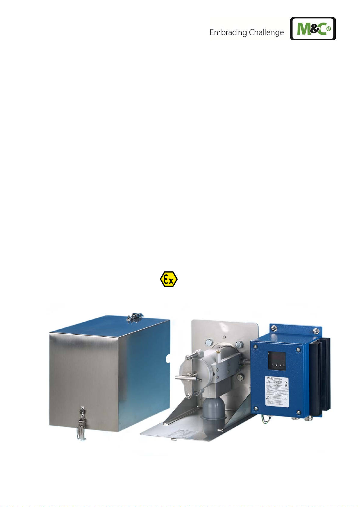
Gas sample probe Series SP
®
Version SP3200V /.../HEX5-x.08
Version SP3200 /.../RS/HEX5-x.08
II 3 GD
Gas sampling and gas conditioning technology 2-1.3.9-ME
Page 2

Contents
1 Equipment standard ........................................................................................................................... 3
2 Safety information .............................................................................................................................. 3
3 Information on the use in hazardous areas ...................................................................................... 4
4 Guarantee ............................................................................................................................................ 4
5 Terms and signals used in this manual .............................................................................................. 4
6 Application .......................................................................................................................................... 5
7 Description .......................................................................................................................................... 5
8 Options ................................................................................................................................................ 7
8.1 Backflush unit type /RS ................................................................................................................................................... 9
8.2 Option /R, /BB and /BBF for test gas feeding or backflushing via check valve R 1/4“, BB 3/8“
or BBF 3/8“ ........................................................................................................................................................................... 9
8.3 Option /CC, /CCF test gas feeding before or behind the probe filter to be selected by the user ..... 10
8.4 Option /C/I test gas feeding via check valve behing the probe filter with pneumatic stop
valve of the probe outlet to the process ............................................................................................................... 10
8.5 Option 2-Way ball valve............................................................................................................................................... 10
8.6 Option spun glass cartridge FW ............................................................................................................................... 10
8.7 Option /3VA test gas feeding and backflushing VIA 3/2-Way ball valve ................................................... 10
8.8 Ball valve drive MS1 ...................................................................................................................................................... 11
8.9 Option /2X second sample gas outlet on the probe ......................................................................................... 11
8.10 Option /PT100 ADditional PT100 with terminal box for external temperature control ....................... 11
8.11 Probe heating .................................................................................................................................................................. 12
9 Technical Data ................................................................................................................................... 12
10 Receipt of goods and storage .......................................................................................................... 15
11 Preparations for installation ............................................................................................................ 15
12 Mountage .......................................................................................................................................... 16
13 Electrical connection .........................................................................................................
................ 20
14 Starting-up ........................................................................................................................................ 21
15 Maintenance ...................................................................................................................................... 21
15.1 Replacement of the filter element ........................................................................................................................... 22
15.2 Replacement of the preliminary filter ..................................................................................................................... 22
15.3 Cleaning of the probe .................................................................................................................................................. 22
16 Shutdown .......................................................................................................................................... 23
17 Spare parts list ................................................................................................................................... 23
18 Annex ................................................................................................................................................. 23
Figures
Figure 1 Probe SP3200(V) without options with preliminary filter V20 .................................................................... 6
Figure 2 Schematic view of the options for backflush and test gas feeding .......................................................... 8
Figure 3 Function scheme of the option 3/2-way ball valve /3VA........................................................................... 11
Figure 4 Schematic drawing of the filter housing cover ............................................................................................. 17
Figure 5 Removal of the filter housing cover .................................................................................................................. 18
Figure 6 SP3200 RS, HEX5-1.08 .............................................................................................................................................. 24
Figure 7 SP3200 RS, HEX5-2.08 .............................................................................................................................................. 25
This Operating Manual does not claim to be complete and is subject to technical changes.
©02/2004 M&C TechGroup GmbH. Reproduction of this document or its content is not allowed without permission from M&C.
3. Edition: 07/2013
2 Gas sampling and gas conditioning technology 2-1.3.9-ME
Page 3

1 EQUIPMENT STANDARD
The equipment standard of the gas sample probe and the options correspond to the safety requirements of
EC Directive 94/9/EG.
The respective type of protection depends on the variant (see table 4).
Manufacturer: M&C TechGroup GmbH
Rehhecke 79
40885 Ratingen – Germany
Tel.: 02102/935-0
E-Mail: info@mc-techgroup.com
www.mc-techgroup.com
2 SAFETY INFORMATION
Please observe the following fundamental safety precautions when using the device:
Read these operating instructions carefully before start-up and use of the device! The
information and warnings given in these operating instructions must be heeded.
The declaration of conformity must strictly be observed (see enclosure).
Work on electrical equipment may only be carried out by qualified personnel in ac-
cordance with the regulations actually valid.
When erecting high-voltage power installations with rated voltages up to 1000 V, the
requirements of VDE 0100 and its associated standards and regulations must be observed.
For use of the device in hazardous areas, the relevant national and international
standards and regulations must be observed.
The device must be connected to a mains supply with the same voltage as specified
on the rating plate.
Protection against contact with high electrical voltages:
The device must be safely isolated from the mains supply before it is opened. The
same applies to any connected external control circuits.
Only use the device within the permissible temperature ranges.
Check that the location of the device is weatherproof. Do not expose it directly to rain
or liquids.
Installation, maintenance, control and eventual repairs may only be carried out by
authorized personnel. Such work must be carried out in accordance with the applicable rules and regulations.
2-1.3.9-ME Gas sampling and gas conditioning technology 3
Page 4

3 INFORMATION ON THE USE IN HAZARDOUS AREAS
Please see the identification of the individual variants in table 4.
Detailed information and a copy of the declaration of conformity are contained in the appendix to these operating instructions. The devices must be installed and used in accordance with the conditions and installation instructions given in the EX-Certificate (see appendix). Only then, a safe operation in hazardous areas is guaranteed.
Any changes to the standard configuration with unspecified parts or parts not authorised
by M&C as well as repair or service work with unspecified parts leads to an immediate loss
of ex-certification.
- In case of any doubt, please contact directly M&C or your M&C franchise dealer.
4 GUARANTEE
In the event of a device failure, please contact M&C directly or your M&C franchise dealer.
The device is covered by a one-year warranty starting from the day of delivery according to our normal terms
and conditions of sale and assuming a technically correct use of the unit. Wearing parts are not covered by
the warranty. The warranty includes free repair at our factory or free replacement of the device which must
be sent to us carriage paid and correctly packed.
5 TERMS AND SIGNALS USED IN THIS MANUAL
QUALIFIED
PERSONNEL
The term QUALIFIED PERSONNEL denotes people who are familiar with the installation,
start-up, maintenance and operation of the product and have the necessary qualification by training or instruction.
The warning and notice symbols mean important information on the product or specific parts of these operating instructions to which special attention should be paid.
This symbol emphasizes important information on the product or specific parts of
these operating instructions referring to use in hazardous areas.
4 Gas sampling and gas conditioning technology 2-1.3.9-ME
Page 5

6 APPLICATION
The probes of type SP3200V.. and SP3200.. are used for continuous gas sampling in dust-laden processes or
processes with high temperatures (according to table 5, chapter 10) or high gas moisture. The modular construction of the probes and the variety of possible options guarantee optimum adaptation of the probes to
complex process and environmental conditions.
The probes of the type SP3200V.. and SP3200.. are available in both, an unheated and an electrically heated
version.
The probes must not be used for sampling of gases or gas mixtures that could be explosive,
even in absence of air or which change safety-relevant material properties. The gases or gas
mixtures must also not contain any solid particles that could generate ignitable friction or percussion sparks in combination with the materials of the probe.
It is not allowed that during operation potential sources of ignition (e.g. smouldering or burning particles, glowing embers, foreign objects) are brought into the gas sample probe.
7 DESCRIPTION
The probes type SP3200(V).. have been designed for easy use, long life and uncomplicated service and
maintenance.
The internal filter element can be replaced without the need of tools or dismounting of the sample line. After
having removed the internal filter element, both the filter chamber and the sample tube can be cleaned easily.
SP3200V and SP3200 (combustible gases and dust):
The gas sample probes type SP3200V.. and SP3200.. are suitable for the sampling of gases and installation
in hazardous areas of zone 2 or 22 (combustible gases and dust). The only difference between both types is
the sealing material of the filter housing. Version SP3200 has got a filter housing sealing out of graphite for
special types which are heated above 185°C. Version SP3200V has got filter housing seals of Viton for special
types which are heated below or up to 185°C. The probe housing and all options are suitable for use in hazardous areas of zone 2 or 22 (combustible gases and dust). Please read the identification in table 4.
The probe SP3200(V).. must not be used for gas sampling in zone 0/1.
The filter system of type SP3200(V).. is suitable for dusts of a fineness of up to 2 μm.
Behind the filtration, i.e. at the outlet of the gas sample probe, the sample gas is free of dust. This means that
in the absence of explosive sample gas downstream analysers can be used without any special protective
measures.
2-1.3.9-ME Gas sampling and gas conditioning technology 5
Page 6
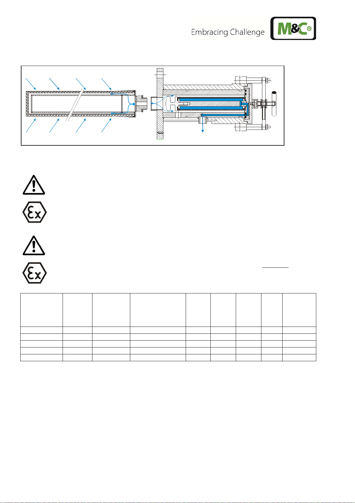
The following figure shows the basic version of the gas sample probe SP3200(V) with prefilter.
Figure 1 Probe SP3200(V) without options with preliminary filter V20
SP3200V / SP3200:
In case the gas-dust mixture to be examined must be classified as potentially explosive because
it contains combustible gases, only downstream devices (flowmeters, analysers) with corresponding identification according to directive 94/9/EC must be used. Suitable explosion isolation with a flame arrestor must be established. Any downstream units are not covered by this
operating manual.
For sampling with probe SP3200(V) from explosion zone 2 sample tubes or pre-filters and
extension tubes can be choosen from tables 1 – 3 below.
For sampling with probe SP3200(V) from explosion zone 22 a pre-filter has to be choosen
from table 2 below. Additional extension tubes from table 3 can be choosen.
Sample tube
Type
SP2000/SS
SP2000/SS-Vm
SP2000/HC
SP2000/KA
SP2000/IC
Part
No.
20S9065
20S9067
20S9090
20S9080
20S9072
max. temper-
ature
°C
600 Stainl. steel 1.4571 1000 2500 G 3/4“a 25/22 37
600 Stainl. steel 1.4571 1000 2500 G 3/4“a 25/06 37
900 Hastelloy C4 1000 2500 G 3/4“a 25/22 37
1300 Kanthal / 1.4571 1000 1500 G 3/4“a 27/20 37
1200 Incoloy 956 1000 2000 G 3/4“a 25/22 37
Material
Tube / Connection
part
Length
mm
Length
„L max“
mm
Connec-
tion
thread
„G“
Tube ø
o/i
[mm]
Connection
ø o
[mm]
Table 1 Sample tube for use with probe SP3200(V)
6 Gas sampling and gas conditioning technology 2-1.3.9-ME
Page 7
Type Part-Nr. Material
Filter in the probe:
S-3 SS150
S-2K150
Option spun glass cartridge FW
Filter FW (spun glass) 93S2083
Preliminary filters to be selected:
SP2000ST/V20-T
SP2000ST/V12-1A-1
SP2000ST/V20-0
SP2000ST/V20-0/HC
SP2000ST/V20-1
SP2000ST/V20-1/HC
SP2000ST/V20-1/HC 0,5μm
SP2000ST/V20-3
Table 2 Possible filters and preliminary filters for use inside the probe
90F0126
90S0020
20S9315
20S9559
20S9105
20S9115
20S9145
20S9155
20S9156
20S9300
1.4404 150 x 30 2
Ceramic Aerolith 150 x 30 2
Spun glass, high temperature resistant
PTFE needled felt (antistatic)
Al2O3/SIC 500x40 1
1.4404 200x50 3
Hastelloy x 200x50 3
1.4404 500x60 3
Hastelloy x 500x60 3
Hastelloy x 500x60 0,5
1.4404 1000/300x31 3
Dimension
[mm]
450x40 3
The preliminary filters can be extended with the following extension tubes.
Extension [mm]
with volume displacer
500 20S9165
1000 20S9170 Not suitable for pre-filter SP2000/V12-1A-1
1500 20S9175 Not suitable for pre-filter SP2000/V12-1A-1
Art. no.
Filter porosity[m]
Table 3 Extension tubes
8 OPTIONS
The following options are suitable for use in hazardous areas. Please read the identification for the respective
zone in table 4.
When selecting options, attention must be paid to the operating parameters.
2-1.3.9-ME Gas sampling and gas conditioning technology 7
Page 8
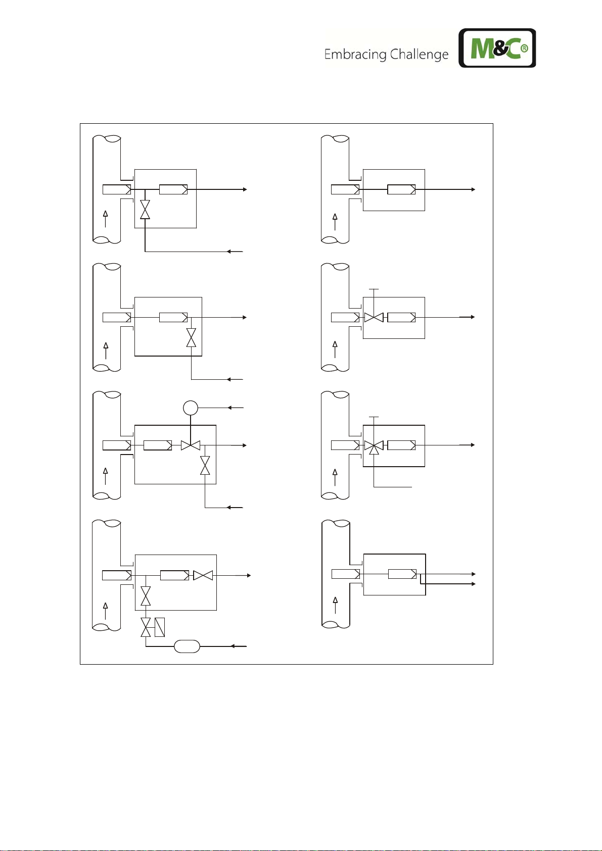
Scheme test gas feeding or backflushing
Entn a h m e so nd e
Sa m p le Pr o b e
R / BB
Option
Option
CCF
Entn a h m e so nd e
Sa m p le Pr o b e
BBF
Option
Option
CC
Entn a hm e so nd e
Sa m p l e Pro b e
Meßgasausgang
Sa m p le o u t
Prüf g a s/ Rüc ksp ülung
Cal. gas/ pure gas
Meßgasausgang
Sa m p l e o ut
Prüf g a s/ Rüc ksp ülung
Cal. gas/ pure gas
i-L uft
I-Air
Meßgasausgang
Sa m p l e o ut
Entn a h m e so nd e
Sample Probe
Entn a hm e so nd e
Sa m p l e Pro b e
Option
VA
Entn a hm e so nd e
Sa m p l e Pro b e
Meßgasausgang
Sa m p l e o ut
Meßgasausgang
Sa m p le o u t
Meßgasausgang
Sa m p le o u t
Option
Option
C/I
Entn a h m e so nd e
Sa m p le Pr o b e
Option
RS
Prü fg a s
Cal. gas
Meßgasausgang
Sa m p l e o ut
Rückspülung
Pure g a s
Prüfgas oder Rückspülung
Cal. gas or pure gas
Entn a h m e so nd e
Sa m p le Pr o b e
Option
Figure 2 Schematic view of the options for backflush and test gas feeding
2X
3VA
Meßgasausgang
Sa m p l e o ut
Meßgasausgang
Sa m p l e o ut
8 Gas sampling and gas conditioning technology 2-1.3.9-ME
Page 9

General safety instructions for back flushing and feeding of calibration gas
A backflushing gas suitable for the sampling point must be selected for backflushing.
The backflushing pressure / calibration gas pressure must always be higher than the process
pressure. This minimum pressure must be monitored with a press switch at the inlet side of the
accumulator or the check valve. If the flush gas pressure drops below the process pressure, the
backflushing solenoid valve must not be operated.
The maximum permissible pressures of 6 bar abs. must not be exceeded (see technical data).
Do not choose back flush intervals longer than 3 seconds because in case of strong pollution of
the pre-filter pressure inside the probe would be rising and than discharging to the analyser via
the patented pressure control valve in the outlet of the probe due to a defined leak rate of this
valve.
At sampling points with inerting, backflushing must be performed with corresponding inert gas.
It must be ensured that the inert gas does not introduce oxygen or combustible gases into the
system.
8.1 BACKFLUSH UNIT TYPE /RS
The backflush unit type /RS consists of a pressure relief valve, solenoid valve, accumulator and patented
pressure control valve in the probe outlet.
The cyclical operation of the solenoid valve and monitoring of the backflushing pressure must be effected
externally. The electrical connection of the solenoid valve must be made in an EEx e connection box. An additional solenoid valve in the sample gas outlet of the probe is not necessary because the patented pressure
control valve shuts the probe outlet during back purging in order to protect the downstream analysis against
the pressure push of the back purge.
8.2 OPTION /R, /BB AND /BBF FOR TEST GAS FEEDING OR BACKFLUSHING VIA CHECK VALVE R 1/4“,
BB 3/8“ OR BBF 3/8“
For back purging of the probe tube or the preliminary filter, flush gas is fed via the check valve. Hereby, it is
recommended to separate the downstream analysing system from the probe in order to avoid pressure
pushes to the system (Option /I). The opening pressure of the check valve is 0,7 bar. The flush gas or calibration gas pressure should be higher than 0,7 bar.
Options /R and /BB are for backflush of the inside space of the probe and the preliminary filter, the option
BBF is for backflush of the probe filter and the preliminary filter.
NOTE!
In order to avoid the cooling down of the inside probe, it is recommended to effect the
backflush in short intervals of <1s.
During the feeding of test gas, the analyse system remains connected. The quantity of test gas should be at
least 25% higher than the quantity of sample gas which is taken in by the analysing system, thus avoiding a
mixture with the test gas. For processes with overpressure, this kind of feeding the test gas is not recommended. In this case, you should use an integrated ball valve in the inlet of the probe as stop valve.
2-1.3.9-ME Gas sampling and gas conditioning technology 9
Page 10

In principle, you need only a small quantity of test gas for probes with an integrated ball valve, because the
probe is separated from the process when the ball valve is activated so that there is no danger of a mixture
with the process gas.
In case of manual operation, please turn the turning handle to the right side until the limit stop in order to
shut off the probe.
NOTE!
In case of low pressure operation, please take into consideration that as from 300 mbar
secondary air will be taken in via the non-closed check valve.
8.3 OPTION /CC, /CCF TEST GAS FEEDING BEFORE OR BEHIND THE PROBE FILTER TO BE SELECTED BY
THE USER
The normal execution ex our works provides the feeding of test gas before the probe filter (Function /CC). By
changing the insert in the fitting for the check valve against the insert additionally attached, this function can
be changed so that test gas can be fed behind the probe filter (Function /CCF).
8.4 OPTION /C/I TEST GAS FEEDING VIA CHECK VALVE BEHING THE PROBE FILTER WITH PNEUMATIC
STOP VALVE OF THE PROBE OUTLET TO THE PROCESS
By activating the pneumatic stop valve with compressed air, the measuring gas way behind the probe filter is
shut off. Now, you can feed test gas via the check valve to the sample gas outlet of the probe without any
loss.
8.5 OPTION 2-WAY BALL VALVE
For any service work, eg. changing of the filter element or cleaning works, the stop valve in the probe inlet is
actuated from outside with the turning handle. This becomes necessary eg. in case of overpressure in the
process or in case of toxic gas components.
In case of toxic gas components, please backflush the probe after shut off and before opening!
8.6 OPTION SPUN GLASS CARTRIDGE FW
For option FW the filter element is dropped and a spun glass cartridge is mounted at the filter housing lid.
This spun glass cartridge is filled with a high temperature resistant spun glass. The option FW is used at sample points with risk of quickly blocking filter surfaces due to taar or sticky substances.
The use of standard filter elements S-3SS150 oder S-2K150 is not possible with option FW.
8.7 OPTION /3VA TEST GAS FEEDING AND BACKFLUSHING VIA 3/2-WAY BALL VALVE
With the 3/2-way ball valve, you can execute both functions „backflushing“ and „test gas feeding“ one after
the other. Only one operation each may be automated via the pneumatic actuation.
10 Gas sampling and gas conditioning technology 2-1.3.9-ME
Page 11

This kind of gas feeding provides the advantage that during backflushing the downstream analyse system is
automatically separated from the probe respectively, the probe is automatically separated from the process
during test gas feeding. For that reason, you need a lower quantity of test gas as no mixture with the process
gas may occur.
For the measuring operation, the ball valve must be put into the central position.
For backflushing, the ball valve must be put into the corresponding position. This means in case of manual
operation to turn the handle from the central position to the left side as far as it will go.
For the test gas feeding, the ball valve must be turned to the right side as far as it will go.
For the measuring operation, return the ball valve into the neutral position.
Ball valve position
Fi- gure
3 Function scheme of the option 3/2-way ball valve /3VA
Measuring
Ball valve position
Blow back
Ball valve position
Test gas
8.8 BALL VALVE DRIVE MS1
The following drives are available:
Pneumatic drive with spring return type MS/ NC or NO
Hereby 2 operating conditions can be realised:
a. Using a shut off ball valve VA the conditions:
"Open=measuring" and "shut".
b. Using a 3/2-way ball valve 3VA either the conditions:
"Open=measuring" and "blow back" or
"Open=measuring" and "test gas feeding"
Type MS-C for test gas feeding and type MS-B for blow back.
When placing the order specify, if the ball valve is
NC, (shut without control air), or
NO, (open without control air). Standard = NC
8.9 OPTION /2X SECOND SAMPLE GAS OUTLET ON THE PROBE
With this option, the probe has got two sample gas outlets ¼“ NPTi.
8.10 OPTION /PT100 ADDITIONAL PT100 WITH TERMINAL BOX FOR EXTERNAL TEMPERATURE CON-
TROL
Additional PT100 (2-conductors) with separate terminal box mounted on the probe.
The screwed cable gland has got a terminal range of 7-12 mm.
2-1.3.9-ME Gas sampling and gas conditioning technology 11
Page 12

8.11 PROBE HEATING
The probe heating type HEX5-x.08 is suitable for temperature ranges of 85°C -185°C. It consists of a heating
plate with heating cartridges and a control electronic.
For the heater type HEX5.1.08, the control electronic is mounted onto the probe. This means a range of the
ambient temperature for the probe of 0 – 50°C.
The probe heating type HEX5.2.08 is designed for an external mounting of the control unit (in Ex zone 2). For
the electrical connection, a terminal box is mounted on the probe which means an ambient temperature
range of 0 – 70°C. The externally mounted control unit can be used within an ambient temperature range of
0 – 50°C.
Technical data may be taken from the separate operating manual HEX5-x.08.
9 TECHNICAL DATA
Gas sample probe type SP3200V (up to 185 °C) SP3200 (more than 185 °C)
Part No. 20S5705 20S5700
Weather protection shield yes
Filter housing material Stainless steel 316 / 316Ti
Sealing materials Graphite, FPM Graphite
Probe flange sealing material Graphite
Pre-filter / sample tubes optional, see data sheet 2-1.1.0.6 and 2-1.1.0.8
Sample pressure max. 0,5-6 bar
Ambient temperature -20 °C to max. 200 °C depending on the temperature class
Permissible process gas temperature depending on the temperature class, however max. 200°C at the probe entry
Filter chamber volume 120 cm3
Filter element, porosity F-3SS150= stainless steel*, 3 micron S-2K150= ceramic**, 2 micron
Sample gas outlet connection 1x 1/4“ NPTi for max. 8mm-tube connectors
Connection gas outlet at option RS 6 mm Swagelok connector
Mounting flange DN65 PN6, FormB, SS316Ti* >DN or ANSI possible**
Weight 7 kg
Option heating type HEX5 HEX5-1.08 HEX5-2.08
Part No. 20S9650 (a) 20S9655 (a)
Temperature controller integrated (on the probe) externally
Mounting controller in the Ex-zone 2 and 22
Control electronic
Power supply 240V 50/60Hz max. 800W, alternatively 120V,50/60Hz max. 830W
Electrical connection cable gland, terminal range 6-12mm, terminals max. 4mm2
Marking
12 Gas sampling and gas conditioning technology 2-1.3.9-ME
II 3 G Ex nA nC nL IIC T5 to T2,
II 3 D Ex tD A22 IP65 T75°C to T235°C
Class I, Division 2, Groups A/B/C/D, T5 - T2B
Page 13

Temperature controller
II3G Ex nA nC nL IIC T5 to T2
II3D Ex tD A22 IP65 T75°C to T235°C
Class I, Div. 2, Groups A/B/C/D T5 – T2B
Admissible medium temperature on the probe
inlet
Power max. 800 W (240V), max. 830 W (120V)
Case protection IP65; EN60529
Operating temperature 0°C to max. 230°C according to T-class, pls. indicate with order.
Ambient temperature 0 °C to +50 °C controller: 0 °C bis +50 °C, heating termi-
The admissible medium temperature is limited by the materials used (< 200°C)
and by the maximum admissible surface temperatures as shown in table 4.
nal box: -20 °C bis +70 °C
Low temperature alarm contact
Excess temperature limiter +5°C to Tsoll, manual reset
Option back purge unit type RS RS
Part No. 20S5560 (a)
Power supply 230V 50/60Hz 9W or 115V 50/60Hz 9W (a)
Electrical connection cable 3x1mm2
Marking
Connection G 1/2”i at the buffer vessel
Max. back purge pressure 6 bar abs.
Volume buffer vessel 2 liters
Ambient temperature -20°C to 60°C
Option 2-way-ball valve in the probe entrance /VA
Part No. 20S9050
Operating temperature -20°C up to 185°C
Option 2/3-way-ball valve in the probe entrance
Part No. 20S9325
5°C to Tset, capacity 250V 3A AC, 0,25A DC.
1 contact NO, potentialfree.
II 3GD T4
/3VA
Backflush / Test gas connection 6mm tube
Operating temperature -20°C up to +185°C
Option pneum. drive for ball valve /VA o. /3VA MS1
Part No. 20S9055
Connection control air G1/4” i
Pressure control air 5-10 bar
Option valve for blowback or calibration gas
1/4”
Part No. 20S9045
Opening pressure >0,7 bar
Connection 6mm tube
Maximum blow back pressure 6 bar abs.
Maximum operating temperature +185 °C
Option variable calibration gas feeding /R + /CC and /CCF
2-1.3.9-ME Gas sampling and gas conditioning technology 13
/R
Page 14

Part No. 20S9045 + 20S9012
Way of test gas /R/CC = via sample gas outlet or /R/CCF = via probe filter element
Check valve /R check valve 1/4”
Opening pressure >0,7 bar
Connection 6mm tube
Maximum blow back pressure 6 bar abs.
Maximum operating temperature +185 °C
Option high performance blow back valve /BB /BBF
Part No. 20S9008 20S9006
Way of blow back gas via filter chamber via probe filter element
Check valve high performance check valve 3/8”
Opening pressure >0,7 bar
Connection 8mm tube
Maximum blow back pressure 6 bar abs.
Maximum operating temperature 185 °C
Option test gas valve / shut-off valve /C + /I
Part No. 20S9011 + 20S9009
Way of test gas via sample gas outlet with shut-off to the process
Check valve check valve 1/4”
Opening pessure >0,7 bar
Connection 6mm tube
Shut-off valve bellow-type valve with pneumatic drive
Pressure control air 3-10 bar
Connection control air 1/8” NPT i
Option second sample gas outlet /2X
Part No. 20S9015
Connection 1/4” NPT i
Option spun glass cartridge /FW
Part No. 20S9047 20S9046
Material SS316Ti, Novapress SS316Ti, Graphite
Maximum surface temperature of the gas sample probe:
The maximum surface temperature of the gas sample probe depends on the temperature of the
process medium and the options used (heating HEX5-x.08 and backflush /RS). Under no circumstances, the sample probes SP3200(V)… must exceed the maximum surface temperature
fixed by the temperature class.
The maximum surface temperatures and inferable temperature classes of the gases are shown
in the following table.
14 Gas sampling and gas conditioning technology 2-1.3.9-ME
Page 15

The intended use of the probe restricts the process medium temperature at the probe inlet and
the choice of options to the extent that the maximum surface temperature must lie below the
temperature limit given in table 5 for the combustible gases used or must correspond to the
temperature class of the combustible gases used.
Gas sample probe SP3200(V) for gas sampling out o f processes with combustible gases
Variants
Identification
Max. medium tempera-
ture at the probe inlet [°C]
Max. surface temperature
[°C]
Temperature class
SP3200(V)/HEX5-x.08
and all options
II 3 G
T2 – T5
Corresponding to the
operating temperature of
the selected temperature
class for
the heating,
see table 4.1
limiter temperature of the
T2 – T5
Corresponding to the
selected temperature
class for the heating,
see table 4.1
Table 4 Maximum surface temperatures for the use of heating HEX5-x.08
Temperature classes
T-Class ATEX
Cenelec/IEC/Nec 505
T2 T2 230 235
T2A 215 220
T3 T3 185 190
T3A 165 170
T3B 150 155
T3C 145 150
T4 T4 120 125
T4A 105 110
T5 T5 85 90
T-Class
NEC 500
Operating temperature
°C
Limiter
°C
Table 5 Temperature classes for use of heating HEX5-x.08
T2 – T5
Corresponding to the
selected temperature
class for the heating,
see table 4.1
10 RECEIPT OF GOODS AND STORAGE
The probe and any special accessories should be unpacked carefully immediately upon delivery and
checked against the delivery note for completeness.
The delivery should be checked for transport damage and the transport insurer notified immediately
of any damage.
The gas sample probe is usually delivered in two packages:
- gas sample probe with the necessary fastening bolts, nuts and flange gasket;
- sample tube or preliminary filter – possibly with extension tube.
The probe should be stored in a room protected from frost!
11 PREPARATIONS FOR INSTALLATION
2-1.3.9-ME Gas sampling and gas conditioning technology 15
Page 16

First make sure that conditions at the intended place of use correspond to the data on
the rating plate.
The temperature of the process must be taken into account when selecting the sam-
pling point.
Heating of the probe above the temperature limit given in table 5 must be prevented.
It must be ensured that the temperature class of the probe corresponds to the ig-
nition temperatures of the combustible gases/vapours.
Select the optimum sampling point in accordance with general guidelines or agree on a
sampling point with the responsible authorities.
Place the sampling point in such a way that there is sufficient space for installation and
removal of the probe. Do not forget to include the insertion length of the sample tube
in your considerations.
Easy access to the probe must be ensured to facilitate later maintenance work.
The customer-side sample nozzle should be dimensioned so that the temperature of the
nozzle is always above the process dew point to prevent corrosion and blockages.
If the ambient temperature in the area of the nozzle is higher than 60°C due to radiant
heat, a radiant heat reflective plate must be installed locally to protect the probe.
The mounting flange connection for the nozzle should be DN65 PN6. If another connec-
tion size is desired, an optional intermediate flange adapter /SO10 is available.
The necessary minimum flange size or minimum nozzle diameter depends on the diam-
eter of the sample tube or preliminary filter used.
The prevailing operating parameters must be checked against the following table prior to installation:
Operating parameters for the combustible gas (SP3200(V))
Gas composition corrosive toxic explosive
Zone classification process side
Zone classification environment
Ignition temperature of the gases/vapours °C
(>max. surface temper-
ature from table 4)
Explosion group IIA IIB IIC
Corresponds to tem-
perature class
Process conditions
Low pressure/ excess pressure situation mbar mbar
Process temperature °C, min. °C max.
What parameters should be measured, eg.
02, CO, SO2, NOX,..,
Required gas flow rate l/h, min. l/h, max.
Necessary T90 time sec.
Table 6 Operating parameters
Vol.% mg/Nm³ ppm
12 MOUNTAGE
The M&C probes SP3200 und SP3200V have been developed for stationary use. With correct selection and
installation, they will guarantee many years of trouble-free service with a minimum of maintenance.
We recommend a horizontal mounting position with the sample gas outlet showing downwards (this is not
absolutely essential for proper functioning of the probe). The probe should be installed with an inclination of
approximately 10° with respect to the process.
16 Gas sampling and gas conditioning technology 2-1.3.9-ME
Page 17

The following procedure is recommended:
Remove the probe cover after opening the two toggle-type fasteners.
Work on the gas sample probe may only be carried out when the process and environment
have been declared to non-hazardous areas, i.e. they are free of explosive atmospheres.
Figure 4 Schematic drawing of the filter housing cover
Turn handle A about one full turn anticlockwise so that the cover is lifted.
Place handle C in position E.
Swing out clamp B to the left (in the direction of G).
Pull out the filter housing cover with handle A.
The following figures illustrate the steps described above.
2-1.3.9-ME Gas sampling and gas conditioning technology 17
Page 18

Figure 5 Removal of the filter housing cover
Check that the filter element is screwed on firmly.
Insert the filter holder part again.
The filter holder part is closed in reverse order.
Push the ¾" flat gasket on to the thread of the preliminary filter or extension tube, screw the filter or
tube into the ¾” internal thread in the flange and tighten.
If the sample nozzle does not match with the size of the standard flange connection DN65 PN6, mount the
optional flange adapter attached to the consignment on to the probe in the same way.
Place the flange gasket on to the sample nozzle.
Insert the complete probe unit into the process-side sample nozzle and screw tight with the nuts and
bolts delivered.
12.1 CONNECTION OF THE SAMPLE LINE
A ¼” NPT internal thread is provided on the probe side for connection of the sample line. Suitable con-
necting unions for explosion-protected lines in the sizes Ø 6 mm (standard), 8 mm or 10 mm can be
screwed into this thread using PTFE sealing tape.
The fittings must be tightened carefully to avoid damaging the internal components. The fittings must not be overtightened.
In case of leaks, do not tighten the fittings further. Instead, the relevant fitting should be re-
18 Gas sampling and gas conditioning technology 2-1.3.9-ME
Page 19

moved completely and then refitted.
Then check the connection for leaks.
The sample line is connected as follows:
Loosen the toggle-type fasteners on the isolating cover and remove the cover.
Loosen the thumb screw of the heat conducting plates and remove the plates.
Screw a suitable union into the probe head using sealing tape.
Remove the top part of the sample line mounting clamp and insert the sample line through the sili-
con cap in the bottom part of the bracket plate and into the union.
Screw off the top part of the mounting clamp. In the case of larger sample line diameters it might be
necessary for centric mounting of the sample line to move a little the small mounting bracket of the
mounting clamp after having loosened the two screws and then tighten again.
Connect the line to the union. For Swagelok
®
fittings:
- Insert the line with supporting sleeve fully into the union.
- Tighten the union nut finger-tight.
- Before tightening, mark the union nut in 6 o’clock position.
- Grip the body with a spanner and tighten the union nut by 1¼ turns; after a full turn, the marking must be turned further to 9 o’clock position.
Then place the heat conducting plates in the guide slots on the side of the sample gas connection
and tighten with the thumb screw.
A supporting sleeve must always be used when connecting hose assemblies to stainless steel
unions.
The connection must be checked for leaks.
When using the option backflushing unit /RS the corresponding line must be connected to the accumulator.
A backflushing gas suitable for the sampling point must be selected for backflushing.
The backflushing pressure must always be higher than the process pressure. This minimum
pressure must be monitored at the inlet side of the accumulator with a pressure monitoring
switch. If the flush gas pressure drops below the process pressure, the backflushing solenoid
valve must not be operated.
2-1.3.9-ME Gas sampling and gas conditioning technology 19
Page 20

T
At sampling points with inerting, backflushing must be performed with corresponding inert gas.
It must be ensured that the inert gas does not introduce oxygen or combustible gases into the
system.
The backflushing pressure must not exceed 6 bar abs..
Do not choose back flush intervals longer than 3 seconds because in case of strong pollution of
the pre-filter pressure inside the probe would be rising and than discharging to the analyser via
the pressure control valve in the outlet of the probe due to a defined leak rate of this valve.
Now, refit the cover and fasten it with the toggle-type fasteners.
6
The probe and all options must be earthed. The bleeder resistor must be < 10
everywhere.
The function of the probe must be monitored by a flow controller at the downstream analyser. A steady decline in the sample gas flow can be an indication of the need for maintenance
work on the probe. The probe must be serviced when the flow rate drops below 50%.
We also recommend the installation of an additional submicron filter in front of the analyser system.
- Further information can be found in the Internet at www.mc-techgroup.com.
13 ELECTRICAL CONNECTION
A wrong supply voltage can damage the device. Make sure that the supply voltage corresponds to the voltage shown on the rating plate before connecting the device.
he requirements of VDE 0100 and its associated standards and regulations must be observed
when erecting high-voltage power installations with rated voltages of up to 1000 V! In any case,
we recommend the use of heat-resistant cables.
An external main switch must be provided.
For option /RS, the cable of the solenoid valve must be connected in a suitable EEx e connection box.
A fuse suitable for the rated current of the solenoid valve (max. 3xIB per DIN 41571 or IEC 127)
or protective motor switch with short-circuit and thermal rapid release (set on the rated current) must be installed in front of the solenoid valve as short circuit protection. The rated voltage of the fuse must be equal to or higher than the specified rated voltage of the solenoid
valve. The breaking capacity of the fuse link must be equal to or higher than the maximum
conceivable short circuit current at the place of installation (usually 1500 A). The fuse value is
specified on the magnet coil – Fuse 0.1 A for 230V/50Hz or 0.2A for 115V/60Hz.
20 Gas sampling and gas conditioning technology 2-1.3.9-ME
Page 21

The solenoid valve should be operated cyclically every 60 minutes (carry out min. 1 pulse/s).
Please read the electrical connection of the heating in the separate operating instructions of the heating
HEX5-x.08.
14 STARTING-UP
The requirements of VDE 0100 and its associated standards and regulations must be observed
when erecting high-voltage power installations with rated voltages of up to 1000 V.
An external main switch must be provided.
For option /RS, the control circuit of the solenoid valve must be protected with a 0.1A
fuse.
T
Make sure that the supply voltage corresponds to the voltage shown on the rating plate before starting the
device.
Switch on the power supply.
Caution: In ambient temperatures higher than 40°C, the temperature at the protective or isolating cover is
higher than 60°C.
15 MAINTENANCE
When working during operation:
High surface temperatures!
Touching the surfaces can result in burns. Wear protective gloves.
Aggressive condensate possible!
Wear safety goggles and suitable protective clothing.
The requirements of VDE 0100 and its associated standards and regulations must be observed
when erecting and servicing high-voltage power installations with rated voltages of up to 1000
V!
Work on the gas sample probe must only be carried out when the environment has been declared as non-hazardous area, i.e. it is free of explosive atmospheres.
The process side must also be declared as non-hazardous area – free of explosive atmospheres
– before the filter chamber is opened.
The backflushing unit must be switched off before the filter chamber is opened.
2-1.3.9-ME Gas sampling and gas conditioning technology 21
Page 22

The gas sample probe with preliminary filter and internal filter must be checked for temperature and dust deposits in suitable intervals of time depending on the process conditions. Dust
layers of more than 5 mm must be removed immediately. The filters must be checked for damage and replaced if necessary. Also remove the dust deposits under the cover.
The probe must be shut down when the respective maximum surface temperature is exceeded.
The system and process-specific safety measures must be observed for all maintenance work.
Maintenance intervals cannot be recommended. They must be determined on site depending on the specific
application and process conditions. An indication of the need for maintenance work on the probe can be a
steady decline in the sample gas flow to the analyser system.
15.1 REPLACEMENT OF THE FILTER ELEMENT
Maintenance of the probe is mainly limited to replacement of the filter elements and inspection of the seals
and gaskets. For this:
Remove the protective cover after opening the toggle-type fasteners.
Dismount the filter holder part (see figure 3).
Unscrew the filter thumb screw and replace the filter element.
Inspect the filter element seals and replace them if necessary.
Inspect the flat graphite gasket or Viton gasket in the cover and replace if necessary.
Clean the filter chamber.
Insert the filter holder part again and tighten hand-tight.
Fit the protective cover.
Possibly necessary spare gaskets must be out of graphite or Viton.
15.2 REPLACEMENT OF THE PRELIMINARY FILTER
The complete probe unit must be removed from the process before replacing the preliminary filter. The preliminary filter can, depending on the type and degree of contamination, be cleaned mechanically or in an
ultrasonic bath and is then reusable.
15.3 CLEANING OF THE PROBE
The gas sample probe must be inspected at suitable intervals in time. Dust layers of more than 5 mm must be
removed immediately. The dust deposits under the cover must also be removed.
To prevent static charging, the probe should always be cleaned with a moist cloth.
22 Gas sampling and gas conditioning technology 2-1.3.9-ME
Page 23

16 SHUTDOWN
Before shutdown, i.e. switching off the heater, the probe should be flushed with a suitable inert gas to prevent condensation of aggressive components of the process gas.
17 SPARE PARTS LIST
Wear, tear and replacement part requirements depend on specific operating conditions.
The recommended quantities are based on experience and they are not binding.
Gas sample probe SP3200 and SP3200V
(C) Consumable parts
(R) Recommended spare parts
(S) Spare parts
Part No. Indication
90 F 0126
90 S 0020
93 S 0055
93 S 0020
93 S 0025
93 S 0030
90 S 2072
90 S 2084
Recommended quantity being in operation [years]
C/R/S
Filter element F-3SS150, 1.4404, 3 μm, 150 mm
Filter element S-2K150, ceramic, 2 μm, 150 mm
Gasket (30) for filter element, material graphite R 4 8 12
O-ring (39) for lid SP3200V, material FPM R 2 4 8
O-ring (55) for lid SP3200V, material FPM R 2 4 8
Gasket (69) for lid SP3200, material graphite R 2 4 8
Gasket for sample tube, 3/4", material graphite R 1 2 3
Flange seal DN65PN6 (67mm i.), material graphite R 1 1 1
C 6 12 18
C 6 12 18
1 2 3
18 ANNEX
Drawing SP3200 RS, HEX5-1.08
Drawing SP3200 RS, HEX5-1.08
EC – Declaration of conformity
Further product documentation can be found in the internet under: www.mc-techgroup.com
2-1.3.9-ME Gas sampling and gas conditioning technology 23
Page 24

Figure 6 SP3200 RS, HEX5-1.08
24 Gas sampling and gas conditioning technology 2-1.3.9-ME
Page 25

Figure 7 SP3200 RS, HEX5-2.08
2-1.3.9-ME Gas sampling and gas conditioning technology 25
Page 26

26 Gas sampling and gas conditioning technology 2-1.3.9-ME
Page 27

2-1.3.9-ME Gas sampling and gas conditioning technology 27
Page 28

28 Gas sampling and gas conditioning technology 2-1.3.9-ME
 Loading...