

Page 1
Operating Manual
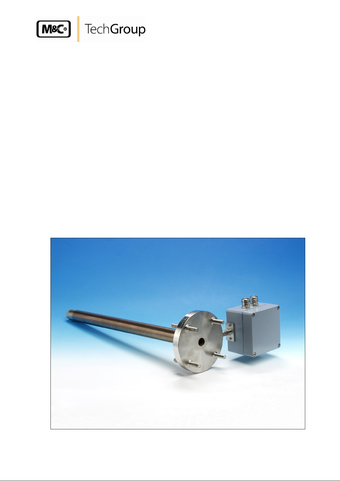
Electrically heated sample probe tube
series SP®, version SP 30-H../EX2
for operation in ex-zone 2
Gas sampling and gas conditioning technology 2-1.9.6EXME
Page 2

2
This Operating Manual does not claim completeness and may be
subject to technical modifications.
© 10/2009 M&C TechGroup Germany GmbH. Reproduction of this
document or its content is not allowed without permission from M&C.
1st Edition: 10/2009
Dear customer,
we have made up this operating manual in such a way that all necessary information about the
product can be found and understood quickly and easily.
Should you still have any question, please do not hesitate to contact M&C directly or go through your
appointed dealer. Respective contact addresses are to be found in the annexe to this operating
manual.
Please also contact our homepage www.mc-techgroup.com for further information about our
products. There, you can read or download the data sheets and operating manuals of all M&C
products as well as further information in German, English and French.
Gas sampling and gas conditioning technology 2-1.9.6EXME
Page 3

3
Content
1 General information ................................................................................................................... 4
2 Declaration of conformity .......................................................................................................... 4
3 Electrical standards ................................................................................................................... 5
4 Safety instructions ..................................................................................................................... 5
5 Information and safety instructions for using the tube in hazardous areas ........................ 6
6 Warranty ...................................................................................................................................... 6
7 Used terms and signal indications ........................................................................................... 7
8 Application .................................................................................................................................. 8
9 Description .................................................................................................................................. 8
9.1 Heated sample tube SP30-H../EX2 and SP30-H1.1-V/EX2 ................................................. 8
9.2 Temperature controller ......................................................................................................... 9
10 Technical Data .......................................................................................................................... 10
11 Preparation for Installation ...................................................................................................... 11
12 Mounting ................................................................................................................................... 11
13 Electrical connections ............................................................................................................. 12
13.1 Electrical connection of the heated sample tube ................................................................ 13
14 Starting ...................................................................................................................................... 14
15 Maintenance .............................................................................................................................. 15
16 Cleaning .................................................................................................................................... 15
List of illustrations
Figure 1 Dimensions SP30-H../EX2 ......................................................................................... 8
Figure 2 SP30-H1.1-V/EX2 ...................................................................................................... 9
Figure 3 Mounting of the heated sample tube SP30-H../EX2 ................................................ 12
Gas sampling and gas conditioning technology 2-1.9.6EXMD
Page 4
4
Head Office
M&C TechGroup Germany GmbH Rehhecke 79 40885 Ratingen Germany
Telephone: 02102 / 935 - 0
Fax: 02102 / 935 - 111
E - mail: info@mc-techgroup.com
www.mc-techgroup.com
1 GENERAL INFORMATION
The product described in this operating manual has been examined before delivery and left our works
in perfect condition related to safety regulations. In order to keep this condition and to guarantee a
safe operation, it is important to heed the notes and prescriptions made in this operating manual.
Furthermore, attention must be paid to appropriate transportation, correct storage, as well as
professional installation and maintenance work.
All necessary information a skilled staff will need for appropriate use of this product are given in this
operating manual.
2 DECLARATION OF CONFORMITY
CE - Certification
The product described in this operating manual complies with the following EC directives:
ATEX-Directive
The product described in this manual is produced in accordance with the EC directive for devices and
protection systems for appropriate use in hazardous areas 94/9/EG appendix II.
EMV-Instruction
The requirements of the EC directive 2004/108/EC “Electromagnetic compatibility“ are met.
Low Voltage Directive
The requirement of the EC directive 2006/95/EC “Low Voltage Directive“ are met.
The compliance with this EC directive has been examined according to DIN EN 61010.
Declaration of conformity
The EU Declaration of conformity can be downloaded from the M&C homepage or directly requested
from M&C.
Gas sampling and gas conditioning technology 2-1.9.6EXME
Page 5

5
3 ELECTRICAL STANDARDS
The electrical standard of electrical equipment corresponds to the safety regulations concerning the
EN 60079-15, EN 61010 and the EC directive 94/9/EC-ATEX100a (equipment group 3 in hazardous
areas);
Producer : M&C TechGroup Germany GmbH
Rehhecke 79
40885 Ratingen
Germany
4 SAFETY INSTRUCTIONS
Please note the following basic safety procedures when using this equipment:
Read these operating instructions carefully before start-up and use of the equipment! The information
and warnings given in these operating instructions must be heeded.
Work on electrical equipment is only to be carried out by trained specialists as per the regulations
currently in force.
Attention must be paid to the requirements of VDE 0100 when setting high-power electrical units with
nominal voltages of up to 1000V, together with the associated standards and stipulations.
For use in hazardous area observe the relevant national and international instructions and
regulations.
Check the details on the type plate to ensure that the equipment is connected up to the correct mains
voltage.
Protection against touching dangerously high electrical voltages. Before opening the equipment, it
must be switched and hold no voltages. This also applies to any external control circuits that are
connected.
The equipment is only to be set within the permitted range of temperatures and pressures.
Check that the location is weather-protected. It should not be subjected to either direct rain or
moisture.
Installation, maintenance, monitoring and any repairs may only be done by authorised personnel with
respect to the relevant stipulations.
Gas sampling and gas conditioning technology 2-1.9.6EXMD
Page 6

6
NOTE!
Installation and operation have to be done corresponding to the
manual. Only in this case the reliability of the operation in the
hazardous area can be guaranteed.
5 INFORMATION AND SAFETY INSTRUCTIONS FOR USING THE TUBE IN
HAZARDOUS AREAS
The electrically heated tube is suitable for using in hazardous area category 3G.
The explosion proof protection is:
II 3G Ex nA IIC temperature class T5 to T2 (temperature class corresponding to your order).
All changes of the standard configuration with parts which are not specified or approved by M&C as
well as repair and service with not specified parts means a loss of the Ex-certificate.
In case of doubt please turn directly to M&C respectively to your M&C franchised dealer.
6 WARRANTY
If the equipment fails, please contact M&C directly or else go through your M&C authorised dealer.
We offer a one year warranty as of the day of delivery as per our normal terms and conditions of sale,
and assuming technically correct operation of the unit. Consumables are hereby excluded. The terms
of the warranty cover repair at the factory at no cost or the replacement at no cost of the equipment
free ex user location. Reshipments must be send in a sufficient and proper protective packaging.
Gas sampling and gas conditioning technology 2-1.9.6EXME
Page 7

7
DANGER!
This means that death, severe physical injuries and/or important
material damages will occur in case the respective safety measures
are not fulfilled.
WARNI N G!
This means that death, severe physical injuries and/or important
material damages may occur in case the respective safety
measures are not fulfilled.
CARE!
This means that minor physical injuries may occur in case the
respective safety measures are not fulfilled.
CAR E !
Without the warning triangle means that a material damage may
occur in case the respective safety measures are not met.
ATT E NTION!
This means that an unintentional situation or an unintentional status
may occur in case the respective note is not respected.
NOTE!
These are important information about the product or parts of the
operating manual which require user’s attention.
SKILLED STAFF
These are persons with necessary qualification who are familiar with
installation, use and maintenance of the product.
NOTE!
These are important information about the product or parts of the
instruction manual referring to operating in hazardous areas.
7 USED TERMS AND SIGNAL INDICATIONS
Gas sampling and gas conditioning technology 2-1.9.6EXMD
Page 8

8
NOTE!
The heated sample tubes SP30-H../EX2 and SP30-H1.1-V/EX2 can be
mounted in Ex-zone 2.
8 APPLICATION
The electrically heated M&C sample probe tube SP30-H../EX2 is used in extractive sampling systems
to avoid cooling and condensation of the sample in the insitu tube from the sample point to the heated
sample probe SP3200-H. It can be used for sampling from Ex-zone 2 and mounting in Ex-zone 2. To
avoid a premature demage by cooling and condenstaion in dust loaded processes, we recommend a
heated tube type SP30-H1.1-V/EX2, including an insitu pre-filter V20-2/30, heated up with the tube.
Hereby an early blocking or destruction is avoided.
9 DESCRIPTION
9.1 HEATED SAMPLE TUBE SP30-H../EX2 AND SP30-H1.1-V/EX2
The electrically heated M&C sample tube SP30-H../EX2 is available in 0,6 m and 1,0 m, length (L1 in
Fig. 1 and 2). Other length on request.
With a mounting flange with 4 welded screws the heated sample tube SP30-H../EX2 can be easily
fixed both to the flange at the sample point and the probe head e.g. SP3200-H.
The heated sample tubes SP30-H../EX2 are equipped with a G3/4"i thread connector at the tube end.
This enables fixing a standard non heated sample tube or pre-filter to the heated insitu tube.
The electrical cartridge heater is located inside a double tube system, completely separated from the
process. At the version SP30-H1.1-V/EX2 the included large pre-filter V20-2/30 is heated up with the
sample tube.
The tube versions SP30-H../EX2 have an internal diameter of 22 mm.
The internal diameter of the version SP30-H1.1-V/EX2 is reduced to 6 mm to optimize the tube dead
volume.
The sample tubes SP30-H2/EX2 have a temperature sensor PT100 for max. 200 °C operating
temperature.
The sample tubes SP30-H1.1/EX2 and SP30-H1.1-V/EX2 have a temperature sensor Fe-CuNi for
max. 320 °C operating temperature.
Figure 1 Dimensions SP30-H../EX2
Gas sampling and gas conditioning technology 2-1.9.6EXME
Page 9

9
Figure 2 SP30-H1.1-V/EX2
9.2 TEMPERATURE CONTROLLER
The temperature control has to be mounted externally.
Function and correctness of the temperature control is in the authority of the operator.
Gas sampling and gas conditioning technology 2-1.9.6EXMD
Page 10

10 TECHNICAL DATA
Serie SP®
SP30-H1.1/EX2
SP30-H2/EX2
SP30-H1.1-V/EX2
Temperature sensor
Fe-CuNi
PT100 2-wire
Fe-CuNi
Temperature controller
external
Probe tube length L1
max. 1 m
Sample temperature
depending on the temperature class (see table temperature class). Please
specify with order.
Operating temperature
depending on the temperature class (see table temperature class). Please
specify with order.
Pre-filter
optional
optional
V20-2/30 insitu filter
length 520 mm, 60
mm, filter porosity 2μm,
integrated and heated
Sample gas inlet
connection
G3/4"i DIN ISO 228/1
pre-filter with G1 1/2"i
DIN ISO 228/1
Dust loading
max. 2 g/m3
>2 g/m3
Probe tube volume
380 ml/m
420 ml
Sample pressure
max. 5 bar g
Ambient temperature
-20 °C to +70 °C
Storage temperature
-20 °C to +70 °C
Ready for operation
2 h
Power supply
230V 50/60Hz or 115V 50/60Hz
Heating capacity
0,6m: 600W, 1m: 800W, (other length/capacities on request)
Electrical connections
terminals, max. 4 mm2, 2x PG13,5 cable gland, terminal range 6-12mm
Electrical standard
EN 61010, EN60519-1
Degree of protection
IP54 EN 60529
Ex-marking
II 3 G Ex nA II T5 to T2 see table temperature class
Mounting flange
DN65 PN6, Form B with 4 welded screws on both sides M 12x 40 mm
Material of parts in contact
with the sample
stainless steel 1.4539
1.4539,
SS316Ti/SS316
Temperature class
Operating/sampling temperature
°C
Limiter
°C
T2
280
290
T3
185
190
T4
120
125
T5
85
90
10
Gas sampling and gas conditioning technology 2-1.9.6EXME
Page 11

11
Under / over pressure situation
mbar
bar
Process temperature
°C Min.
°C Max.
Dust loading
g/m³
Dust composition - grain size
µm
Gas composition
corrosive
toxic
explosive
Which parameters should be measured,
e.g. O2, CO, SO2, NOX,...,
Vol.%
mg/Nm³
ppm
Required amount of gas
l/h
Min.
l/h
Max.
Necessary T90 time
sec.
WARNI N G!
The permitted ambient temperature for the connection box of the
sample tubes SP30-H../EX2 and SP30-H1.1-V/EX2 is -20 to +70°C.
11 PREPARATION FOR INSTALLATION
Select the optimal sampling point in accordance with the generally applicable guidelines or consult the
competent persons.
Locate the sampling point in such a way that there is adequate space for inserting and removing the
probe and pay attention to the insertion length of the probe tube.
Make certain that the probe is easily accessible so that you can carry out any subsequent
maintenance work without trouble.
If the ambient temperature in the area of the connections is >70°C as a result of radiated heat, then a
radiated-heat deflector must be mounted to protect the probe.
The connection's mounting flange connection should comply with DN65 PN6. If other connection sizes
are required, the stud bolts of the heated sample tube can be arranged accordingly as option.
The necessary minimum flange size and the minimum connection diameter depends on the diameter
of the probe tube or pre filter used.
Before mounting, the probe must be adjusted to the existing operating conditions.
The existing operational parameters are to be checked accordingly prior to commencing mounting
work (see also technical data, chapter 10):
12 MOUNTING
Put flange sealings on the threaded bolts of the heated sample tube.
Screw together gas sample probe with threaded bolts of the heated sample tube.
Screw together gas sample probe at the sampling connection piece with threaded bolts on the
process side of the heated sample tube.
Gas sampling and gas conditioning technology 2-1.9.6EXMD
Page 12

12
WA R N ING!
When connecting the equipment, please ensure that the supply
voltage is identical with the information provided on the model
type plate.
NOTE!
Attention must be paid to the requirements of IEC 364 (DIN VDE
0100) when setting high-power electrical units with nominal
voltages of up to 1000 V, together with the associated standards
and stipulations.
In any case we recommend the use of temperature resistant cable !
A main switch and matching fuse must be provided externally!
The main circuit must be equipped with a fuse corresponding to
the nominal current (over current protection); for electrical details
see technical data.
It is recommended to use the low temperature alarm. In case of an
alarm the flow can be stopped and the components downstream
the probe are safe for demage.
NOTE!
Function and correctness of the temperature control (temperature
class) is in the sole responsibility of the installer and operator.
Figure 3 Mounting of the heated sample tube SP30-H../EX2
13 ELECTRICAL CONNECTIONS
Gas sampling and gas conditioning technology 2-1.9.6EXME
Page 13

13
WA R N ING!
The used cables for the connection of the heating must have an
outer diameter of 6-12mm corresponding to the clamping range of
the cable glands!
WARNI N G!
The max. admissible ambient temperature for the connection box
of the sample tubes SP30-H../EX2 and SP30-H1.1-V/EX2 is +70°C.
Temperature resistant cable have to be used corresponding to the
max. temperature at the installation site.
NOTE!
Function and correctness of the temperature control (temperature
class) is in the sole responsibility of the installer and operator.
Connection
13.1 ELECTRICAL CONNECTION OF THE HEATED SAMPLE TUBE
Remove lid of the connection box. In the lid there is also the electrical wiring plan.
Insert the power cable (min. 3 x 1,5 mm2) coming from the external temperature controller
through the cable gland and connect it at the corresponding terminals 2, 5 and 6.
Insert the temperature sensor cable through the other cable gland and connect it to the
terminals 7 and 8.
Remount lid.
Gas sampling and gas conditioning technology 2-1.9.6EXMD
Page 14

14 STARTING
WA R N ING!
Before starting up check whether the mains power supply
voltage corresponds with the information stated on the
nameplate.
WA R N ING!
Start up only the built-in heated probe tube because otherwise
there is a risk of burning !
WA R N ING!
Check whether the housing of the heating controller and the
connection box of the heated sample tube are earthed. Earth
resistance <0,3 Ohm.
NOTE!
Function and correctness of the temperature control (temperature
class) is in the sole responsibility of the installer and operator.
Temperature class
Operating/sampling temperature
°C
Limiter
°C
T2
280
290
T3
185
190
T4
120
125
T5
85
90
14
Switch on mains power supply.
Then inner temperature of the sample tube has to be measured during the heat-up phase.
The maximum temperature reached is the value for the temperature class. This has to be
taken from the table below. Adjust desired temperature via controller.
The nameplate contains no information about the temperature class because this is
determined by the temperature controller only.
Gas sampling and gas conditioning technology 2-1.9.6EXME
Page 15

15 MAINTENANCE
WARNI N G!
The safety instructions specific to the plant and process are to be
consulted prior to any maintenance work!
DANGER!
Caution, danger of explosion!
Under voltage do not take the device off the mains !
WA R N ING!
When working during operation:
High surface temperatures!
Touching the surfaces can result in burns. Wear protective gloves
and protect against unauthorized access !
WA R N ING!
Work on the gas sample probe may only be carried out when the
environment has been declared an explosion-free zone, i.e. it is
free of explosive atmospheres.
The requirements of VDE 0100 and its associated standards and
regulations must be observed when erecting and servicing highvoltage power installations with rated voltages to 1000V !
NOTE!
In case of external contamination of the connection box and the
temperature controller housing clean these only with a cloth
wetted with soapy water.
15
16 CLEANING
Gas sampling and gas conditioning technology 2-1.9.6EXMD
Page 16

16
EG - Konformitätserklärung
EC declaration of conformity
im Sinne der EG Richtlinie über elektrische Betriebsmittel zur Verwendung innerhalb bestimmter
Spannungsgrenzen 2006/95/EC und
according the EC directive about electrical equipment for use within certain limits of voltage
2006/95/EC and
im Sinne der EG-Richtlinie für Geräte und Schutzsysteme zur bestimmungsgemässen Verwendung in explosionsgefährdeten
Bereichen 94/9/EG Anhang II und
in accordance with the EC directive for devices and protection systems for appropriate use in hazardous areas 94/9/EG
appendix II and
im Sinne der EG Richtlinie über die elektromagnetische Verträglichkeit 2004/108/EC
according the EC directive about the electromagnetic compatibility 2004/108/EC.
Hiermit erklären wir, daß folgender elektrisch beheiztets Entnahmerohr mit Regler
Herewith, we declare that the following heated insitu probe tube with Controller
Typ/Type SP30-H../EX2 II 3 G Ex nA II T5 –T2
den grundlegenden Anforderungen der
and is corresponding to the basic requirements of the
EG- Niederspannungsrichtlinie2006/95/EG und der
EC low voltage directive 2006/95/EC and the
EG-Richtlinie für Geräte und Schutzsysteme zur bestimmungsgemässen Verwendung in explosionsgefährdeten Bereichen
94/9/EG Anhang II und der
EC directive for devices and protection systems for approriate use in hazardous areas 94/9/EG Appendix II and the
EG- Richtlinie über die elektromagnetische Verträglichkeit 2004/108/EC entsprechen.
EC directive about electromagnetic compatibility 2004/108/EC.
Folgende harmonisierte Normen wurden angewandt:
The following harmonized standards have been used:
: EN 61010 Teil 1 2002
: EN 61010 part 1 2002
: EN 60079-15 2006
Störaussendung : EN 61000 Teil 6-3 2007
Emission : EN 61000 part 6-3 2007
Störfestigkeit : EN 61000 Teil 6-2 2005
Immunity : EN 61000 part 6-2 2005
Die Funktion und Richtigkeit der Temperaturregelung (Temperaturklasse) liegt in der alleinigen Verantwortung des
Errichters und Betreibers.
The function and accuracy of the temperature control (temperature class) is in the sole responsibility of the raiser
and the operator.
Ratingen, den 31.03.2010
M&C TechGroup GmbH
..........................................
Diese Erklärung bescheinigt die Übereinstimmung mit den genannten Richtlinien, beinhaltet jedoch keine Zusicherungen von
Eigenschaften im rechtlichen Sinne.
This declaration certifies conformance with the above mentioned directives. Affirmation of attributes in a legal sense is not
included.
Die Sicherheitshinweise und Installationsanweisung der mitgelieferten Produktdokumentation sind zu beachten.
Safety declarations and installation instruction given in the product documentation have to be considered.
Gas sampling and gas conditioning technology 2-1.9.6EXME
 Loading...