

Page 1
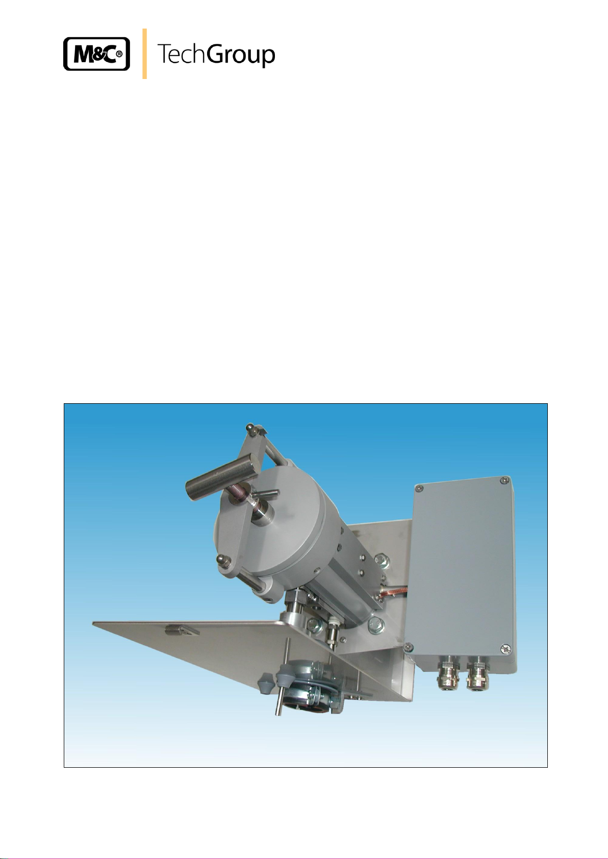
Operating Manual
Series SP ®
Version SP2600-H/C/I/BB/F/0,1GF
and SP2600-H/C/I/BB/F/1K190
Gas sampling and gas conditioning technology 2-1.1.5.1-ME
Page 2

2
This Operating Manual does not claim completeness and may be
subject to technical modifications.
© 05/2006 M&C TechGroup Germany GmbH. Reproduction of this
document or its content is not allowed without permission from M&C.
SP® is a registered trade mark.
2nd Edition: 03/2011
Dear customer,
we have made up this operating manual in such a way that all necessary information about the
product can be found and understood quickly and easily.
Should you still have any question, please do not hesitate to contact M&C directly or go through your
appointed dealer. Respective contact addresses are to be found in the annexe to this operating
manual.
Please also contact our homepage www.mc-techgroup.com for further information about our
products. There, you can read or download the data sheets and operating manuals of all M&C
products as well as further information in German, English and French.
Gas sampling and gas conditioning technology 2-1.1.5.1-ME
Page 3

3
Contents
1 General information ............................................................................................................... 4
2 Declaration of conformity ...................................................................................................... 4
3 Safety instructions ................................................................................................................. 5
4 Warranty .................................................................................................................................. 5
5 Used terms and signal indications ....................................................................................... 6
6 Introduction ............................................................................................................................. 7
6.1 Serial Number ................................................................................................................. 7
7 Application .............................................................................................................................. 7
8 Technical data ......................................................................................................................... 8
9 Description .............................................................................................................................. 8
9.1 Options ............................................................................................................................ 9
10 Receipt of goods and storage ............................................................................................. 10
11 Installation and dimensions ................................................................................................ 10
12 Mounting ............................................................................................................................... 12
12.1 Mounting of the prefilter respectively the sample tube .................................................. 12
12.2 Mounting of the probe ................................................................................................... 12
12.3 Dismounting of the filter housing cover and checking the filter element ........................ 13
13 Supply connections ............................................................................................................. 14
13.1 Pneumatic connection ................................................................................................... 14
13.1.1 Connection of the sample line ............................................................................... 14
13.1.2 Connection of the backpurge and calibration gas ................................................. 15
13.2 Electrical connection ..................................................................................................... 15
13.2.1 Version with internal capillary tube thermostat ...................................................... 16
13.2.2 Version with external temperature regulator .......................................................... 16
14 Starting .................................................................................................................................. 17
15 Closing down ........................................................................................................................ 17
16 Maintenance and repair ....................................................................................................... 18
16.1 Change of the filter element and the sealings ............................................................... 18
17 Spare parts list ...................................................................................................................... 19
18 Annex ..................................................................................................................................... 19
List of illustrations
Figure 1 Construction and dimensions of the SP2600-H/C/I/BB/F/1K190 ............................... 11
Figure 2 Construction and dimensions of the SP2600-H/C/I/BB/F/0,1GF ............................... 11
Figure 3 Mounting of the pre-filter or sample tube ................................................................... 12
Figure 4 Schematic drawing of the filter housing cover ........................................................... 13
Figure 5 Dismounting of the filter housing cover ..................................................................... 14
Gas sampling and gas conditioning technology 2-1.1.5.1-ME
Page 4

4
Head Office
M&C TechGroup Germany GmbH Rehhecke 79 40885 Ratingen Germany
Telephone: 02102 / 935 - 0
Fax: 02102 / 935 - 111
E - mail: info@mc-techgroup.com
www.mc-techgroup.com
1 GENERAL INFORMATION
The product described in this operating manual has been examined before delivery and left our works
in perfect condition related to safety regulations. In order to keep this condition and to guarantee a
safe operation, it is important to heed the notes and prescriptions made in this operating manual.
Furthermore, attention must be paid to appropriate transportation, correct storage, as well as
professional installation and maintenance work.
All necessary information a skilled staff will need for appropriate use of this product are given in this
operating manual.
2 DECLARATION OF CONFORMITY
CE - Certification
The product described in this operating manual complies with the following EC directives:
EMV-Instruction
The requirements of the EC directive 2004/108/EC “Electromagnetic compatibility“ are met.
Low Voltage Directive
The requirement of the EC directive 2006/95/EC “Low Voltage Directive“ are met.
The compliance with this EC directive has been examined according to DIN EN 61010 as well as DIN
57721 for the voltage test of heating elements.
Declaration of conformity
The EU Declaration of conformity can be downloaded from the M&C homepage or directly requested
from M&C.
Gas sampling and gas conditioning technology 2-1.1.5.1-ME
Page 5

5
3 SAFETY INSTRUCTIONS
Please take care of the following basic safety procedures when mounting, starting up or
operating this equipment:
Read this operating manual before starting up and use of the equipment. The information and
warnings given in this operating manual must be heeded.
Any work on electrical equipment is only to be carried out by trained specialists as per the regulations
currently in force.
Attention must be paid to the requirements of VDE 0100 (IEC 364) when setting high-power electrical
units with nominal voltages of up to 1000 V, together with the associated standards and stipulations.
Check the details on the type plate to ensure that the equipment is connected to the correct mains
voltage.
Protection against touching dangerously high electrical voltages:
Before opening the equipment, it must be switched off and hold no voltages. This also applies to any
external control circuits that are connected.
The device is only to be used within the permitted range of temperatures and pressures.
Check that the location is weather-protected. It should not be subject to either direct rain or moisture.
The gas sample probes version SP2600-H.. must not be used in hazardous areas.
Installation, maintenance, monitoring and any repairs may only be done by authorized
personnel with respect to the relevant stipulations.
4 WARRANTY
If the equipment fails, please contact M&C directly or else go via your appointed M&C dealer.
We offer a one year warranty as of the day of delivery as per our normal terms and conditions of sale
and assuming technically correct operation of the device. Consumables are hereby excluded. The
terms of the warranty cover repair at the factory at no cost or the replacement at no cost of the
equipment free ex user location. Reshipments must be sent in a sufficient and proper protective
packaging.
Gas sampling and gas conditioning technology 2-1.1.5.1-ME
Page 6

6
DANGER!
This means that death, severe physical injuries and/or important
material damages will occur in case the respective safety
measures are not fulfilled.
W ARN IN G !
This means that death, severe physical injuries and/or important
material damages may occur in case the respective safety
measures are not fulfilled.
CARE!
This means that minor physical injuries may occur in case the
respective safety measures are not fulfilled.
CAR E!
Without the warning triangle means that a material damage may
occur in case the respective safety measures are not met.
ATT ENT ION !
This means that an unintentional situation or an unintentional
status may occur in case the respective note is not respected.
NOTE!
These are important information about the product or parts of the
operating manual which require user’s attention.
SKILLED STAFF
These are persons with necessary qualification who are familiar
with installation, use and maintenance of the product.
5 USED TERMS AND SIGNAL INDICATIONS
Gas sampling and gas conditioning technology 2-1.1.5.1-ME
Page 7

7
NOTE!
Please indicate the serial number of the equipment in case of any question
and when ordering spare parts.
6 INTRODUCTION
The M&C gas sample probes type SP2600-H.. are based on the patented probe SP2000-H and are
used for continuous gas sampling in processes with a high extent of dust, high temperature and/or
high gas moisture.
6.1 SERIAL NUMBER
The type plates are to be found where the electrical connection box is placed.
7 APPLICATION
Due to its large filter surface and the possibility to back-purge the filter element, the probes SP2600H/C/I/BB/F.. achieve a high service life especially in cases where no pre-filter can be applied. For this
purpose, a back-purge valve and a pneumatic stop valve for the sample gas outlet is integrated in the
probe.
Version SP2600-H/C/I/BB/F/0,1GF is suitable for dusts with extremely fine particles up to 0,1 µm and
version SP2600-H/C/I/BB/F/1K190 can be very efficiently back-purged thanks to the double-ply filter
element and an external filter membrane of 1 µm porosity.
Gas sampling and gas conditioning technology 2-1.1.5.1-ME
Page 8

8 TECHNICAL DATA
Technical Data Series SP
®
SP2600-H/C/I/BB/F/0,1GF
SP2600-H/C/I/BB/F/1K190
Part Number
20 S 3550
20 S 3540
Integrated back purging
Via the filter element
Weather protection cap
yes
Protection terminal box
IP54 EN60529
Materials filter housing
Stainless steel 1.4571, 1.4404
Sealing material
FPM*
Material probe flange sealing
Novapress
Sample tube
optionally
Sampling pressure max.
0,4 – 6 bar* abs.
Ambient temperature
-20 °C bis +60 °C*** /PT100, /Fe-CuNi, /Ni-CrNi** = -20 °C bis +80 °C
Filter housing volume
300 cm3
Filter porosity
0,1 micron
1 micron
Thermostat,
Temperature adjustments
0-180°C* /PT100** /Fe-CuNi** /Ni-CrNi**
Readyness for working
After 40min
Alarm contact for insufficient
temperature
Capacity 250V 3A~, 0,25A=, Switch point: ΔT 30°C to T
SOLL
Connection sample gas
outlet
1 x ¼“ NPTi* Tube connection Ø 6, 8 or 10 mm**
Backpurge connection (BB/F)
Back purging: for tube Ø 8mm
Test gas connection (/C)
Ø 6mm socket piece
Connection stop valve (/I)
Ø 6mm socket piece
Pressure range control air (/I)
3 – 10bar
Power supply
230V 50/60Hz, 800W or 115V 60Hz, 800W (fuse 10A)
Electrical connection
terminals; max. 4 mm², 2 x M20 x 1,5 cable gland
Standard electrical
equipment
EN 61010, EN 60519-1
Mounting flange
DN65 PN6, Form B, 1.4571* >DN or ANSI possible**
Weight
approx. 20 kg*
8
* Standard
** Options
*** If there are high ambient temperatures, please choose option PT100 (Part No. 20S9025) or thermoelement Fe-CuNi or
Ni-CrNi (Part No. 20S9027 resp. 20S9028) instead of thermostat regulator. In this case, an additional electronic
temperature regulator is necessary (see also data sheet 2-5.1).
9 DESCRIPTION
The probe has been designed for easy installation, safe operation, easy maintenance and a great
variety of applications. Depending on the particular problem, various sample tubes or preliminary filters
(see data sheets 2-1.1.0.6 and 2-1.1.0.8), which are not included in the scope of supply of the probe,
are screwed into the G3/4"i thread of the filter holder.
The large surface ceramic or glass fibre filter element is installed outside the process area in a
housing with minimal dead space. The probes are designed for replacement of the filter element
without having to remove the sample line so that contamination of the clean gas side is avoided.
Owing to the special design of the heating element of probe SP2600-H..., the entire filter housing
including mounting flange can be heated adjustable to 180°C, thus ensuring reliable operation without
cooling down below the dew point in the external area.
Gas sampling and gas conditioning technology 2-1.1.5.1-ME
Page 9

9
Description
Part No.
Basic version SP2600-H/C/I/BB/F/0,1GF, heated up to 0-180 °C, with weatherproof
cover, material stainl. Steel 1.4571
20 S 3540
Basic version SP2600-H/C/I/BB/F/1K190, heated up to 0-180 °C, with weatherproof
cover, material stainl. Steel 1.4571
20 S 3550
Power supply 115V/60Hz /115V
20 S 9030
Type with back-flush/calibration gas valve (C*), opening pressure 0,7 bar,
Socket piece 6 mm*
20 S 9435
Type with PT100 sensor instead of capillary controller,
without thermostat /PT100
20 S 9025
Type with thermo-element Fe-CuNi (Typ J) instead of capillary controller,
without thermostat /Fe-CuNi
20 S 9027
Type with thermo-element Ni-CrNi (Typ K) instead of capillary controller,
without thermostat /Ni-CrNi
20 S 9028
Type with second PT100 sensor /2-PT100
20 S 9026
Type with special intermediate flange adapter DN..PN6 or ANSI..150 lbs /DN
20 S 9004
Type with gas pre-heater GVW1, material stainl. Steel 2-1.2.5 /GVW1
20 S 9058
Junction of the gas pre-heater to the connection „BB“ and to the gas inlet /GVW
20 S 9062
Type with steam heating without thermostat and valves instead of the capillary
controller /D
20 S 9033
Temperature control of the standard version takes place by means of an integrated capillary sensor
thermostat with excess temperature limiter and alarm function for insufficient temperature in a compact
arrangement directly on the probe. Test gas feeding is possible via an integrated check valve.
Additional functions of the SP2600-H..:
The calibration gas can be supplied directly at the check valve/C (return valve) to the probe
outlet. Calibration gas supply at the probe is possible without any expensive gas loss via the
otherwise open probe inlet.
The cut-off valve /I cuts off the gas outlet of the heated filter chamber.
The filter element, and via this indirectly, the filter space and sample tube or preliminary filter
can be back-flushed via the check valve /BB/F installed in the heated chamber wall.
9.1 OPTIONS
The following list shows the options available. The diversity of options and the modular design of the
M&C gas sample probes ensure optimum probe selection to suit the particular process and ambient
conditions.
Gas sampling and gas conditioning technology 2-1.1.5.1-ME
Page 10

10
NOTE!
The probe must be stored in a weather-protected and frost-proof area !
NOTE!
Before mounting the probe, you have to check its suitability on the basis of
the given operating parameters. (see type plate).
10 RECEIPT OF GOODS AND STORAGE
Please take the probe and possible special accessories carefully out of the packaging
immediately after receipt and compare the goods with the items listed on the packing list.
Check the goods for any damage caused during delivery and, if necessary, notify your
transport insurance company without delay of any damage discovered.
11 INSTALLATION AND DIMENSIONS
During installation, the prescriptions for accident prevention and safety instructions for mounting and
operation have to be heeded.
Please strictly observe the notifications of chapter 3 „Safety Instructions“.
Furthermore, you have to consider the following:
Select the optimum sampling point according to the prescriptions actually valid and coordinate
with the responsible persons.
Place the sampling point in such a way that sufficient space for mounting and dismounting of the
probe is available. Also consider the insertion length of the sample tube.
Take care of easy access to the probe in order to enable you to execute any maintenance work
necessary in future without problem.
The bleeder connection must be prepared so that the temperature of the connection piece
remains above the acid dew point in order to avoid problem due to corrosion and obstruction.
In case the temperature in the area of the connection piece is >60°C due to radiant heat, you have
to mount a device of sheet steel in order to reflect the radiant heat.
The mounting flange of the connection piece should be connected with size DN65 PN6. Should
you desire other dimensions, we can provide you suitable adapter intermediate flanges as option.
The minimum flange size or connection piece diameter respectively is determined by the sample
tube diameter or pre-filter diameter you apply.
We recommend to mount the probe horizontally with an angle of inclination of 10° to the process.
Gas sampling and gas conditioning technology 2-1.1.5.1-ME
Page 11

11
Figure 1 Construction and dimensions of the SP2600-H/C/I/BB/F/1K190
Figure 2 Construction and dimensions of the SP2600-H/C/I/BB/F/0,1GF
Gas sampling and gas conditioning technology 2-1.1.5.1-ME
Page 12

12
NOTE!
It is recommended to mount the probe with its sample gas outlet showing
downwards (not necessary for perfect function).
Further it is recommended to mount the probe with a slight descending
gradient downwards so that possible deposited drops may flow back into the
process.
CAR E!
The fittings must be tightened carefully in order to protect the integrated
components against damage. Do not screw down the fittings to much.
In case of leakage, do not tighten the fittings further. Dismount the
respective fitting completely, screw in and tighten it again.
Check the connection for tightness.
12 MOUNTING
The M&C probes SP2600-H.. are designed for stationary use and provide a long service life and a
minimum of maintenance work under the premise of professional selection of the sampling point and
professional mounting.
12.1 MOUNTING OF THE PREFILTER RESPECTIVELY THE SAMPLE TUBE
The pre-filter or sample tube is mounted together with a suitable sealing by screwing into the
G ¾“ thread of the probe flange.
Figure 3 Mounting of the pre-filter or sample tube
12.2 MOUNTING OF THE PROBE
Remove the protection cover of the probe after having opened both bent-level closures.
Put the flange sealing on the bleeder connection.
Fit the mounting piece and the probe flange by means of the attached screws and screw nuts.
In case the bleeder connection does not fit with the standard flange connection DN65 PN6, please
mount the attached optional adapter flange in the same way onto the probe.
Remove the heat conducting jaws on the sample gas outlet after having unscrewed the knurled
screw. For connection of the sample line, you have to screw in a correctly dimensioned tube joint
connection 1/4"-NPT by using a PTFE sealing tape.
Gas sampling and gas conditioning technology 2-1.1.5.1-ME
Page 13

13
12.3 DISMOUNTING OF THE FILTER HOUSING COVER AND CHECKING THE
FILTER ELEMENT
The filter housing cover is dismounted as followed:
Figure 4 Schematic drawing of the filter housing cover
Turn the toggle handle A approximately one rotation to the left side so that the cover is lifted;
Put the handle C into position E;
Turn the clamp clip B to the left side (direction G);
Pull out the filter housing cover with the toggle handle A.
The photos shall illustrate the above mentioned steps.
Gas sampling and gas conditioning technology 2-1.1.5.1-ME
Page 14

14
Figure 5 Dismounting of the filter housing cover
Now, the filter element is visible.
Check on the filter pressing screw whether the filter element is screwed on tightly.
Push the cover with filter element into the probe again.
Turn the clamp clip B to the right side and bring the ring bolt D into position E by using the handle
C so that the clamp clip locks into place of the ring bolt D and the threaded bolt H. For this
purpose, you may push in or pull out a little the filter housing cover by means of the straining
screw A; afterwards, turn the handle C into position F and screw the toggle handle A hand-tight by
turning to the right.
13 SUPPLY CONNECTIONS
13.1 PNEUMATIC CONNECTION
13.1.1 CONNECTION OF THE SAMPLE LINE
On the probe, a thread ¼“ NPTi is available for connecting the sample line. You can screw in
respective connection joints for lines with dimensions of Ø6mm (standard), 8mm or 10mm.
The sample line is to be mounted as follows:
Loosen the bent-lever closures of the insulating cover and remove the cover;
If you have got the 180°C version, screw the respective screws with insulating tape into
the probe head (see also 12.2);
Gas sampling and gas conditioning technology 2-1.1.5.1-ME
Page 15

15
NOTE!
For the connection of tube lines to stainless steel tube joints, you
must always use a supporting socket.
Check the connection for tightness.
W ARN IN G !
The back-purge pressure must always be higher than the process
pressure. The admissible maximum pressures must not be
exceeded (see technical data).
W ARN IN G !
Incorrect supply voltage may damage the device. When connecting
the equipment, please ensure that the supply voltage corresponds
to the information given on the type plate !
Please install the probes in such a way that any contact of the live
parts is impossible!
We recommend in any case to use heat-resistant cables !
The alarm contact for insufficient temperature must be monitored !
In case of a low temperature alarm (failure of the probe heating or
sensor), the gas sampling must be interrupted in order to avoid a
damage of the probe or downstream components.
Insert the line through the corresponding opening in the bottom of the probe and
through the silicone retainer;
Connect the line to the tube joint. For Swagelok®-Fittings, the following is valid:
- Put the line with supporting socket into tube joint until the limit stop;
Screw the union nut hand-tight;
- Before drawing up, mark the union nut on the “6-a’clock position”;
- Hold the body with a wrench and screw down the union nut by 1 ¼ rotations; after one entire
rotation, the marking has to be turned furthermore up to the “9-a’clock position”.
Place the probe cover again and shut it by both bent-lever closures.
13.1.2 CONNECTION OF THE BACKPURGE AND CALIBRATION GAS
The return valve has got an opening pressure of 0,7bar.
VersionsSP2600-H/C/I/BB/F.. include separate connections for test gas feeding and back-purge gas
(see figure 1 and figure 2):
Back-purge gas for pipe Ø8 x 1mm, and
Calibration gas pipe socket Ø6 x 1mm.
The control of the stop valve /I is made separately within a pressure range of 3 to 10 bar. It is
equipped with a 6mm pipe socket.
13.2 ELECTRICAL CONNECTION
The temperature adjustment of probes type SP2600-H.. is effected with a capillary regulator as
standard. Optionally, the probe can be equipped with a PT100 or thermocouple. This requires the
connection of an external thermostat.
Gas sampling and gas conditioning technology 2-1.1.5.1-ME
Page 16

16
NOTE!
For the erection of high-power electrical units with nominal voltages of up
to 1000V, the requirements of VDE 0100 (IEC 364) must be observed
together with the associated standards and stipulations.
A main switch must be provided externally.
The main circuit of the device must be equipped with a fuse
corresponding to the nominal voltage (over current protection); for
electrical details see technical data.
When mounting the capillary regulator or PID regulator on the sampling
place, the maximum admissible ambient temperature must be heeded (see
chapter 8). In case it is exceeded, you must install a PID regulator
externally and outside the critical temperature zone.
CAR E!
We recommend to use heat-resistant cables !
ATT ENT ION !
If you apply thermocouples, please use corresponding calibration lines !
Mains 230V 50Hz
or 115V 60Hz
Alarm outlet
1
2
1
2
+30
-30
800 W
Mains230V 50Hz
or 115V 60Hz
PT100 or
thermocouple
1
2
1
2
800 W
13.2.1 VERSION WITH INTERNAL CAPILLARY TUBE THERMOSTAT
Remove the lid of the connection box. Inside the lid,
you can find the electrical connection plan as shown
here.
Insert the mains cable ( min. 3 x 1,5 mm2 ) through the
cable gland and connect it to the appropriate terminals.
Insert the signal cable (insufficient temperature alarm)
through the cable entry and connect it to the
appropriate terminals (contact position Tu indicates the
event of alarm).
Screw on the lid again.
13.2.2 VERSION WITH EXTERNAL TEMPERATURE REGULATOR
Remove the lid of the connection box. Inside
the lid, you can find the electrical connection
plan as shown here.
Insert the mains cable ( min. 3 x 1,5 mm2 )
through the cable gland and connect it to the
appropriate terminals.
Insert the temperature sensor cable through
the cable entry and connect it to the
appropriate terminals.
Screw on the lid again.
Gas sampling and gas conditioning technology 2-1.1.5.1-ME
Page 17

17
W ARN IN G !
Please ensure before starting that the mains supply corresponds to
the indication on the type plate !
Be careful when you get in contact with the probe’s surface during
operation. The high surface temperatures may cause burnings.
Protective gloves are to be born and any unauthorized access to
the probe must be made impossible !
NOTE!
In case the adjustment of the temperature set value on the capillary
controller should be changed during operation by more than 30°C
in one step, the thermostat’s excess temperature cut-off is
activated (push the reset key to switch it on again).
NOTE!
The total heat up time is approximately 40 minutes. The probe is
ready for work after having exceeded the below alarm level value (
30°C below set value ).
W ARN IN G !
In case of insufficient temperature (failure of the probe heating), the
feeding of sample gas must be interrupted by appropriate
measures !
14 STARTING
Before starting the equipment for the first time, the safety instructions related to the installation and the
process have to be heeded.
Please consider the appropriate safety requirements and respective measures regarding the mediums
to be extracted.
We recommend the following procedure:
Check the temperature set value on the integrated thermostat or on the external controller.
Switch on power.
15 CLOSING DOWN
Before closing down, i.e. switching off the heating, the probe should be purged with inert gas or air in
order to avoid condensation of aggressive components from the sample gas.
Gas sampling and gas conditioning technology 2-1.1.5.1-ME
Page 18

18
W ARN IN G !
Aggressive condensat is possible. Wear protective glasses and
appropriate protecting clothes !
Attention must be paid when touching the probe surface during
operation. Due to the high surface temperatures, you may suffer
from burnings. Protective gloves have to be born, and the probe
must absolutely be protected against unauthorized access!
Before carrying out any maintenance work on electrical equipment,
the mains voltage must be switched off on all poles. The same is
valid for eventually connected alarm and control circuits!
NOTE!
When carrying out any maintenance of repair work, the probe does
not need being dismounted.
W ARN IN G !
Please ensure that no contaminations that are bad for one’s health
remain on the probe before carrying out any maintenance or repair
work. An appropriate measure is to flush the probe with inert gas.
Before changing the filter element, the gas feeding must be
stopped!
16 MAINTENANCE AND REPAIR
Before carrying out any maintenance and repair work, the specific installation and process safety
measures are to be observed.
We cannot give any recommendation regarding maintenance cycles. This must be determined
specifically depending on the process conditions.
The principal maintenance work of the probe is changing the filter element and control of the sealings.
16.1 CHANGE OF THE FILTER ELEMENT AND THE SEALINGS
The following steps are recommended when changing the filter element or the sealings:
Remove the protection cap after having opened the bent-lever closures;
Dismount the filter housing lid according to 12.3;
Screw out the filter pressing screw, check the filter element and exchange it if necessary;
Check the filter element sealings and exchange them if necessary;
Check the O-rings inside the lid and exchange them if necessary;
Clean the filter chamber;
Mount again the filter housing lid in reverse order and put it into the filter head;
Bolt the filter housing lid according to 12.3;
Put on again the protection cover.
Gas sampling and gas conditioning technology 2-1.1.5.1-ME
Page 19

19
NOTE!
Pay attention that after putting in the filter housing lid the strap bolt is
screwed down hand-tight in cold condition and that it is tightened again after
the operating temperature is reached.
Recommended spare parts
Part-No.
Description
90 S 0030
Spare filter element S-1K190, ceramic, 1µm, 190mm
90 S 0035
Spare filter element S-0,1GF190, glass fiber, 0,1µm, 190mm
93 S 1000
Spare O-ring (68), Viton , for lid SP2600-H/C/I/BB/F..
93 S 1005
Spare O-ring (86), Viton , for lid SP2600-H/C/I/BB/F..
93 S 1010
Spare O-ring (105), Viton , for lid SP2600-H/C/I/BB/F..
90 S 2077
Flange sealing DN65 PN6B (67), for SP2000, SP2600-H/C/I/BB/F..
93 S 0010
Spare thermostat 0-180°C
93 S 0015
Spare heating cartridge HLP, 230V 800W
93 S 0017
Spare heating cartridge HLP, 115V 800W
93 S 0018
Heat conducting paste for putting in the heating cartridge
93 S 2126
Clamp clip LK145 for SP2500/2600
90 S 0050
PTFE adapter for filter element S-0,1GF190
93 S 0059
Spare PT100 SP2000-H, SP2600-H
93 S 0044
Flange sealing (50) for filter element S-1K190, FPM
17 SPARE PARTS LIST
Wear, tear and replacement part requirements depend on the specific operating conditions.
The following table shows an extract of the recommended spare parts for probe of type SP2600-H.. .
18 ANNEX
Additional product information may be seen and downloaded under:
www.mc-techgroup.com
Gas sampling and gas conditioning technology 2-1.1.5.1-ME
 Loading...