

Page 1
Operating instructions
®
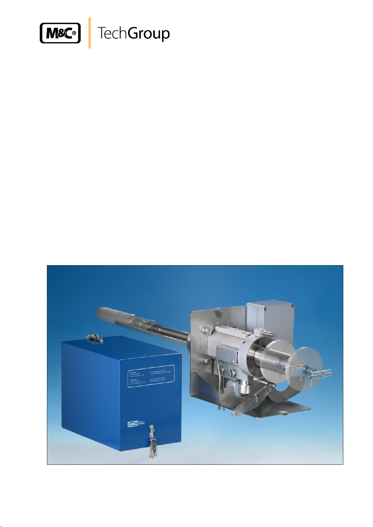
Gas sample probe series SP
Versions SP2500-H, SP2500-H/C/I/BB
SP2500-H/C/I/BB/F
Gas sampling and gas conditioning technology 2-1.1.5-ME
Page 2

2
Contents
1 General information ....................................................................................................................... 4
2 Declaration of conformity ............................................................................................................. 4
3 Safety instructions ......................................................................................................................... 5
4 Warranty ......................................................................................................................................... 5
5 Used terms and signal indications ............................................................................................... 6
6 Introduction .................................................................................................................................... 7
7 Description ..................................................................................................................................... 7
7.1 Options ................................................................................................................................... 10
8 Technical data .............................................................................................................................. 11
9 Dimensions ................................................................................................................................... 12
10 Receipt and storage ..................................................................................................................... 12
11 Installation information ............................................................................................................... 12
12 Installation .................................................................................................................................... 13
12.1 Probe assembly ...................................................................................................................... 13
12.2 Fitting preliminary filter or sample tube ................................................................................... 14
12.3 Connection of sample line ...................................................................................................... 16
12.4 Connection of backflushing and calibration gas line ............................................................... 17
12.5 Electrical connection ............................................................................................................... 17
12.5.1 Versions with internal capillary tube thermostat .............................................................. 18
12.5.2 Version with external thermostat ..................................................................................... 18
13 Starting ......................................................................................................................................... 19
14 Closing down ............................................................................................................................... 20
15 Maintenance ................................................................................................................................. 20
15.1 Replacement of filter element and seals ................................................................................ 21
16 Spare parts list ............................................................................................................................. 22
17 Annex ............................................................................................................................................ 22
List of illustrations
Figure 1 Probe type SP2500-H ...................................................................................................... 8
Figure 2 Probe type SP2500-H/C/I/BB ........................................................................................... 8
Figure 3 Probe type SP2500-H/C/I/BB/F ........................................................................................ 9
Figure 4 Dimensions (mm) of SP2500-H.. probe ......................................................................... 12
Figure 5 Schematic diagram of filter housing cover ..................................................................... 14
Figure 6 Removal of filter housing cover ...................................................................................... 15
Figure 7 Fitting preliminary filter or sample tube .......................................................................... 15
Gas sampling and gas conditioning technology 2-1.1.5-ME
Page 3

3
This Operating Manual does not claim completeness and may be
subject to technical modifications.
© 06/2004 M&C TechGroup Germany GmbH. Reproduction of this
document or its content is not allowed without permission from M&C.
SP® is a registered trade mark.
1st Edition: 06/2004
Dear customer,
we have made up this operating manual in such a way that all necessary information about the
product can be found and understood quickly and easily.
Should you still have any question, please do not hesitate to contact M&C directly or go through your
appointed dealer. Respective contact addresses are to be found in the annexe to this operating
manual.
Please also contact our homepage www.mc-techgroup.com for further information about our
products. There, you can read or download the data sheets and operating manuals of all M&C
products as well as further information in German, English and French.
Gas sampling and gas conditioning technology 2-1.1.5-ME
Page 4

4
Head Office
M&C TechGroup Germany GmbH Rehhecke 79 40885 Ratingen Germany
Telephone: 02102 / 935 - 0
Fax: 02102 / 935 - 111
E - mail: info@mc-techgroup.com
www.mc-techgroup.com
1 GENERAL INFORMATION
The product described in this operating manual has been examined before delivery and left our works
in perfect condition related to safety regulations. In order to keep this condition and to guarantee a
safe operation, it is important to heed the notes and prescriptions made in this operating manual.
Furthermore, attention must be paid to appropriate transportation, correct storage, as well as
professional installation and maintenance work.
All necessary information a skilled staff will need for appropriate use of this product are given in this
operating manual.
2 DECLARATION OF CONFORMITY
CE - Certification
The product described in this operating manual complies with the following EC directives:
EMV-Instruction
The requirements of the EC directive 2004/108/EC “Electromagnetic compatibility“ are met.
Low Voltage Directive
The requirement of the EC directive 2006/95/EC “Low Voltage Directive“ are met.
The compliance with this EC directive has been examined according to DIN EN 61010.
Declaration of conformity
The EU Declaration of conformity can be downloaded from the M&C homepage or directly requested
from M&C.
Gas sampling and gas conditioning technology 2-1.1.5-ME
Page 5

5
3 SAFETY INSTRUCTIONS
Please take care of the following basic safety procedures when mounting, starting up or operating this
equipment:
Read this operating manual before starting up and use of the equipment. The information and
warnings given in this operating manual must be heeded.
Any work on electrical equipment is only to be carried out by trained specialists as per the regulations
currently in force.
Attention must be paid to the requirements of VDE 0100 (IEC 364) when setting high-power electrical
units with nominal voltages of up to 1000 V, together with the associated standards and stipulations.
Check the details on the type plate to ensure that the equipment is connected to the correct mains
voltage.
Protection against touching dangerously high electrical voltages:
Before opening the equipment, it must be switched off and hold no voltages. This also applies to any
external control circuits that are connected.
The device is only to be used within the permitted range of temperatures and pressures.
Check that the location is weather-protected. It should not be subject to either direct rain or moisture.
The equipment must not be used in hazardous areas.
Installation, maintenance, monitoring and any repairs may only be done by authorized personnel with
respect to the relevant stipulations.
4 WARRANTY
If the equipment fails, please contact M&C directly or else go through your M&C authorised dealer.
We offer a one year warranty as of the day of delivery as per our normal terms and conditions of sale,
and assuming technically correct operation of the unit. Consumables are hereby excluded. The terms
of the warranty cover repair at the factory at no cost or the replacement at no cost of the equipment
free ex user location. Reshipments must be send in a sufficient and proper protective packaging.
Gas sampling and gas conditioning technology 2-1.1.5-ME
Page 6

6
DANGER!
This means that death, severe physical injuries and/or important
material damages will occur in case the respective safety measures
are not fulfilled.
W ARN ING !
This means that death, severe physical injuries and/or important
material damages may occur in case the respective safety
measures are not fulfilled.
CARE!
This means that minor physical injuries may occur in case the
respective safety measures are not fulfilled.
CAR E !
Without the warning triangle means that a material damage may
occur in case the respective safety measures are not met.
ATT E NTI ON!
This means that an unintentional situation or an unintentional status
may occur in case the respective note is not respected.
NOTE!
These are important information about the product or parts of the
operating manual which require user’s attention.
SKILLED STAFF
These are persons with necessary qualification who are familiar with
installation, use and maintenance of the product.
5 USED TERMS AND SIGNAL INDICATIONS
Gas sampling and gas conditioning technology 2-1.1.5-ME
Page 7

7
6 INTRODUCTION
M&C SP2500-H.. series probes are used for continuous gas sampling in dust-loaded processes at
high temperatures and high gas moisture.
The probe offers the possibility to remove the preliminary filter or sample tube in the process without
having to remove the probe head for cleaning purposes.
H/C/I/BB and ..-H/C/I/BB/F series probes are used in highly dust-loaded processes. The additionally
installed backflushing valve and pneumatic isolating valve in the sampled gas outlet ensure highly
efficient backflushing of the filter space in the in the probe head and used preliminary filter.
For further information or personal advice, please do not hesitate to contact us or visit us online to
view our wide range of products at:
7 DESCRIPTION
The probe has been designed for easy installation, safe operation, easy maintenance and diversity in
application.
Depending on the particular problem, various sample tubes or preliminary filters (see data sheets 2-
1.1.0.6 and 2-1.1.0.8), which are not included in the scope of supply of the probe, are screwed into the
G3/4"i thread in the filter holder.
The large, ceramic deep-bed filter element (optional glass fibre elements or glass wadding fillings
available) is arranged in a housing with minimal dead space outside the process area.
The probes are designed for replacement of the filter element without the need for tools; as the sample
line does not need to be removed, contamination of the clean gas side is avoided.
Cleaning of the sample tube or preliminary filter takes place by withdrawing the filter part from the
probe without having to remove the probe head.
Owing to the special design of the heating element of SP2500... series probes, the entire probe head
including mounting flange can be heated adjustable to 180°C, thus ensuring reliable operation without
cooling below the dew point externally. Temperature control with the standard version takes place by
means of an integrated capillary sensor thermostat with excess temperature limiter and alarm function
in a compact arrangement directly on the probe.
With the SP2500-H, backflushing or calibration gas supply takes place via an optional check valve
(option C).
Additional functions of the SP2500-H/C/I/BB(/F):
The calibration gas can be supplied directly at the check valve/C to the probe outlet.
Calibration gas supply at the probe is possible without any expensive gas loss via the
otherwise open probe inlet.
The isolating valve /I isolates the gas outlet of the heated filter chamber.
The filter space, sample tube or preliminary filter can be backflushed via the check valve /BB
projecting into the heated filter chamber.
The filter element, and via this indirectly, the filter space and sample tube or preliminary filter
can be backflushed via the check valve /BB/F installed in the heated chamber wall.
Gas sampling and gas conditioning technology 2-1.1.5-ME
Page 8

8
340
(115V,60Hz)
110
260
207
230V,50Hz
Option: 2x
Sample
OUT
Pre-filter
Sample tube
Power
Low temperature
Test gas IN
Test gas
Sample IN
180°C
Sample OUT
>0,7bar
Option:
Option:
2x
Option:
Option: C
alarm
2. sample OUT
Test gas IN
Option: C
345
1/4" NPTi
340
(115V,60Hz)
110
260
207
230V,50Hz
Test gas
IN
Control
IN
Sample
OUT
Pre-filter
Sample tube
Power
Low temperature
alarm
Backflush IN
Tube 6x1
1/8" NPTi
Backflush
Sample IN
180°C
2-6bar
Test gas
Control
Sample OUT
3-10bar
>0,7bar
Backflush IN
1/4" NPTi
Tube 8x1
345
The following figures show the probe types SP2500-H, ...H/C/I/BB, ...H/C/I/BB/F.
Figure 1 Probe type SP2500-H
Figure 2 Probe type SP2500-H/C/I/BB
Gas sampling and gas conditioning technology 2-1.1.5-ME
Page 9

340
(115V,60Hz)
110
260
207
230V,50Hz
Test gas
IN
Control IN
Sample
OUT
Pre-filter
Sample tube
Power
Low temperature
alarm
Backflush
IN
Tube 6x1
1/8" NPTi
Backflush
Sample IN
180°C
2-6bar
Test gas
Control
Sample OUT
3-10bar
>0,7bar
Backflush
IN
1/4" NPTi
Tube 8x1
345
Figure 3 Probe type SP2500-H/C/I/BB/F
9
Gas sampling and gas conditioning technology 2-1.1.5-ME
Page 10

10
Description
Article No.
Basic typeSP2500H, heated to 0-180°C, with weatherproof cover,
Material stainless steel 1.4571
20 S 3510
Basic type SP2500-H/C/I/BB, heated to 180°C, with weatherproof cover,
Material stainless steel 1.4571
20 S 3520
Basic type SP2500-H/C/I/BB/F, heated to 0-180°C, with weatherproof cover,
Material stainless steel 1.4571
20 S 3500
.
Power supply 115V/60Hz/115V
20 S 9030
Type with second sampled gas outlet 1/4" NPTi*/2x*
20 S 9015
Type with backflushing/calibration gas supply valve (C*), opening pressure 0.7 bar,
tube 8 mm*
20 S 9435
Type with glass filter element 0.1GF150, filter fineness 0.1 µm,
seal PTFE/GF150
20 S 9020
Type with special filter housing cover with spun glass cartridge
Including spun glass filling, seal FPM, Novapress/FW
20 S 9047
Type with PT100 sensor instead of capillary controller,
without thermostat/PT100
20 S 9025
Type with thermocouple Fe-CuNi (type J) instead of capillary controller,
without thermostat/Fe-CuNi
20 S 9027
Type with thermocouple Ni-CrNi (type K) instead of capillary controller,
without thermostat/Ni-CrNi
20 S 9028
Type with second PT100 sensor/2-PT100
20 S 9026
Type with special intermediate flange adapter DN..PN6 or ANSI..150 lbs/DN
20 S 9004
Support tube adapter type SP2500H/SA500 for supporting the installation of long sample
tubes and preliminary filters with extension tube, including flange gasket, material 1.4571
20 S 9433
Type with gas pre-heater GVW1, material stainless steel 2-1.2.5/GVW1
20 S 9058
Connection of gas pre-heater to connection “BB“ and gas inlet/GVW
20 S 9062
Type with steam heating without regulating and valves
Instead of capillary controller/D
20 S 9033
7.1 OPTIONS
The following list shows the options available. The diversity of options and modular design of M&C
gas sample probes ensure optimum probe selection to suit the particular process and ambient
conditions.
* only SP2500-H
Gas sampling and gas conditioning technology 2-1.1.5-ME
Page 11

11
Technical data SP
®
series
SP2500-H
SP2500-H/C/I/BB
SP2500-H/C/I/BB/F
Article number
20 S 3510
20 S 3520
20 S 3530
Integrated backflushing
No
Via filter space
Via filter element
Weatherproof cover
Yes
Electrical connection
Terminals; max. 4 mm², 2 x PG13.5 cable gland
Degree of protection of terminal box
IP54 EN60529
Power supply
230V 50/60Hz, 800W or 115V 60Hz, 800W (fuse 10A)
Material of medium contacted parts
Stainless steel 1.4571, 1.4404, FPM*, Graphite**
Ambient temperature
-20°C to +60°C*** /PT100, /Fe-CuNi,/Ni-CrNi** = -20°C to +80°C
Operating temperature
0-180°C* /PT100** /Fe-CuNi** /Ni-CrNi**
Process pressure
0.4 to 6 bar abs.
Ready for operation
after 40min
Alarm contact rating
250V 3A~, 0.25A=, operating point: ΔT 30°C** to T
nominal
Sample gas outlet connection
1/4"-NPT* internal, for tube connection Ø6, 8 or 10mm**
Calibration gas backflushing
connection
1/4“ NPTi*/C**
Backflushing: tube 8mm, calibration gas: tube
6mm
Isolating valve/I connection
1/8“ NPTi
Control air pressure range
3 – 10bar
Filter space volume
280 cm3
Filter fineness
S-2K150= ceramic*, 2µ,/F-0,1GF150= glass fibre**, 0.1µ,/FW= glass
fibre/spun glass**
Mounting flange
DN65 PN6, Form B, 1.4571* >DN or ANSI possible**
Weight
approx. 17kg*
Electrical equipment standard
EN 61010, EN 60519-1
8 TECHNICAL DATA
* Standard
** Optional
*** At high ambient temperatures, the PT100 (Art. No. 20S9025) or thermocouple Fe-CuNi or Ni-CrNi (Art. No. 20S9027 or
20S9028) option should be selected instead of the thermostat. The use of an additional electronic thermostat is
necessary (see also data sheet 4.3).
**** Option only for SP2500-H
Gas sampling and gas conditioning technology 2-1.1.5-ME
Page 12

12
340
110
260
207
345
NOTE!
The probe should be stored protected from frost.
9 DIMENSIONS
The following illustration shows the dimensions of the SP2500-H.. probe.
Figure 4 Dimensions (mm) of SP2500-H.. probe
10 RECEIPT AND STORAGE
The probe and any special accessories should immediately be unpacked carefully upon delivery
and against the delivery note.
The delivery should be checked for any transport damage and the transport insurer immediately
notified of any damage.
11 INSTALLATION INFORMATION
When carrying out installation, the safety rules and regulations for the prevention of accidents must be
observed – this applies similarly to subsequent operation. The information in Chapter 3 “Important
safety information” must be observed in particular.
The following applies:
Select an optimal sample point according to the general guidelines or agree on a sample point
with the responsible authorities.
The sample point should be arranged so that sufficient space for installation and removal of the
probe is available; the insertion length of the sample tube should be taken into account.
Easy access to the probe must be ensured for any necessary maintenance.
The sample nozzle locally should be dimensioned so that the nozzle temperature is always above
the acid dew point to prevent corrosion and blockages.
If the ambient temperature in the area of the nozzle is higher than 60°C due to the radiated heat,
a radiant heat reflective plate must be installed in the area of the nozzle locally to protect the
probe.
Gas sampling and gas conditioning technology 2-1.1.5-ME
Page 13

13
NOTE!
The suitability of the probe must be verified prior to installation by
comparison with the available operating parameters (see rating plate).
NOTE!
In the preferred probe mounting position, the sample gas outlet points
downwards (does not make any difference to the function of the probe).
It is recommended to mount the probe with a slight downward inclination
with respect to the process to enable any precipitated droplets to flow back
to the process.
CAR E !
The fittings must be tightened carefully to avoid damaging the internal
components. The fittings must not be overtightened.
In the event of leaks, the fittings must not be tightened further. The
respective fitting should be removed completely and retightened.
Check unions for leaks.
The nozzle mounting flange connection should be DN65 PN6 or 3“ANSI (115V version). For other
connection dimensions, an optional intermediate flange adapter is available. The necessary,
minimum flange sizes or minimal nozzle diameter depends on the sample tube used or the
preliminary filter diameter.
It is recommended to mount the probe horizontally with an angle of inclination of 10° with respect
to the process.
12 INSTALLATION
M&C SP2500-H.. probes are designed for stationary use and with correct selection of the sample point
and proper installation, they will give many years of trouble-free service with minimum maintenance.
12.1 PROBE ASSEMBLY
Remove the probe cover after opening the two toggle-type fasteners.
Place the flange gasket on the sample nozzle.
Bolt together the mounting support and probe flange with the supplied nuts and bolts.
When using the support tube adapter (for supporting the installation of long sample tubes or
preliminary filters when the probe is installed in a horizontal position), bolt the same between the
nozzle flange and special flange with the threaded bolts.
The supplied sliding segment must be screwed to the sample tube or extension tube of the preliminary
filter about 450mm away from the G3/4“t connecting thread.
If the sample nozzle does not correspond to the standard flange connection DN65 PN6, the optional
supplied adapter flange must be fitted to the probe in the same manner.
Remove the heat conducting plates at the sample gas outlet after loosening the knurled screw.
For connection of the sample line, screw in an appropriately dimensioned union with 1/4"-NPT
connecting thread using PTFE sealing tape.
Gas sampling and gas conditioning technology 2-1.1.5-ME
Page 14

14
12.2 FITTING PRELIMINARY FILTER OR SAMPLE TUBE
The SP2500-H.. probe offers the possibility of fitting or removing the preliminary filter or sample tube in
the process without having to remove the probe head.
For this purpose, the filter housing covers must be removed as follows:
Figure 5 Schematic diagram of filter housing cover
Turn handle A about one full turn anticlockwise, so that the cover is lifted.
Place handle C in position E.
Swing out clamp B to the left (in the direction of G);
Remove the filter housing cover with handle A.
Gas sampling and gas conditioning technology 2-1.1.5-ME
Page 15

15
The following figures show the described steps.
Figure 6 Removal of filter housing cover
Fitting of the preliminary filter or sample tube takes place as follows:
Unscrew the mounting adapter for the preliminary filter or sample tube from the filter housing
cover .
Figure 7 Fitting preliminary filter or sample tube
The filter element is now visible.
Check that the filter element is screwed tight and then screw on the mounting adapter again.
Screw the preliminary filter or sample tube with appropriate seal into the ¾“ thread of the
mounting adapter ;
Gas sampling and gas conditioning technology 2-1.1.5-ME
Page 16

16
NOTE!
When connecting hose assemblies to stainless steel unions, a supporting
sleeve must always be used.
The connection must be checked for leaks.
Push the filter housing cover with preliminary filter or sample tube into the filter space in the
probe head.
Swing clamp B to the right and with handle C bring eye bolt D in position E, so that the clamp
engages in eye bolt D and threaded bolt H; if necessary, push in or pull out the filter housing cover
slightly with the clamping screw A;
Turn handle C into position F and tighten handle A hand-tight by turning clockwise.
12.3 CONNECTION OF SAMPLE LINE
Provided on the probe side for connection of the sample line is a ¼“ NPTi thread. This thread can be
used for screwing in appropriate connecting unions for lines with the sizes Ø6mm (standard), 8mm or
10mm.
The sample line is connected as follows:
Loosen the toggle-type fasteners on the insulating cover and hood and remove.
Screw the appropriate threaded union into the probe head with sealing tape.
Insert the line through the respective opening in the probe base plate and silicone holder.
Connect the line to the union. For Swagelok® fittings:
- Fully insert the liner with support sleeve into the union.
- Tighten the union nut finger-tight.
- Prior to tightening, mark the union nut in the 6 o’clock position.
- Grip the body with a spanner and tighten the union nut with 11/4 turns; after a full turn, the mark
must be turned further to the 9 o’clock position.
Refit the special hood and close with clamps.
Gas sampling and gas conditioning technology 2-1.1.5-ME
Page 17

17
ATT E NTI ON!
The backflushing pressure must be higher than the process pressure.
Pay attention to the maximum pressure level (see technical data).
DANGER!
An incorrect system voltage can damage the device. Ensure that the
system voltage corresponds to the voltage shown on the rating plate
prior to connection!
The probes must be mounted so that any contact with live parts is
impossible!
The use of heat-resistance cable is recommended in any event!
The alarm contact excess temperature must be monitored!
In the event of an excess temperature alarm (failure of the probe
heating or sensor) the sample gas supply must be interrupted to
avoid damaging the probe or subsequent components.
NOTE!
For the erection of power installations with rated voltage up to 1000V,
the requirements of VDE 0100 as well as relevant standards and
specifications must be observed.
An external main switch must be provided.
The supply circuit of the device must be protected with a fuse
corresponding to the rated current (overvoltage protection); electrical
values are shown in the technical data.
When fitting a capillary or PID controller at the sample point, the
maximum permissible ambient temperature must be observed (see
8.). If this temperature is exceeded, a PID controller must be provided
externally and outside the temperature-critical zone.
12.4 CONNECTION OF BACKFLUSHING AND CALIBRATION GAS LINE
SP2500-H:
For option “C”, a check valve is fitted (see Figure 1, opening pressure 0.7bar). Connection of the
backflushing or calibration gas line takes place on the underside of the probe. Provided for this
purpose is a tube with the dimensions Ø8 x 1mm.
The connection for the optional second sample gas outlet is ¼“ NPTi. The thread is closed with a
cover.
SP2500-H/C/I/BB(/F):
In the versions SP2500-H/C/BB and SP2500-H/C/BB/F, separate connections are available for
calibration and backflushing gas (see Figures 2 and 3):
Backflushing gas tube connection Ø8 x 1mm, und
Calibration gas tube connection Ø6 x 1mm.
Control of the isolating valve I takes place separately within a pressure range of 3 to 10bar. This valve
has a 1/8“ NPTi connecting thread.
12.5 ELECTRICAL CONNECTION
Temperature adjustment of the SP2500-H/.. series probes generally takes place with a capillary
controller. The probe can also be provided with an optional PT100 or thermocouple. This requires the
connection of an external thermostat.
Gas sampling and gas conditioning technology 2-1.1.5-ME
Page 18

18
NOTE!
The use of temperature-resistant cable is recommended!
NOTE!
Use appropriate compensating cables for thermocouples!
Power 230V 50Hz
or 115V 60Hz
Alarm output
1
2
1
2
+30
-30
800W
Power 230V 50Hz
or 115V 60Hz
PT100 or
thermocouple
1
2
1
2
800W
12.5.1 VERSIONS WITH INTERNAL CAPILLARY TUBE THERMOSTAT
Remove the connection box cover. The electrical wiring
diagram shown is contained in the cover.
Insert the mains cable (min. 3 x 1.5 mm2 ) through the
cable gland and connect to the appropriate terminals.
Insert the signal cable (low temperature alarm) through
the cable entry and connect to the appropriate terminals
(contact position Tu indicates alarm).
Screw the cover back in place again.
12.5.2 VERSION WITH EXTERNAL THERMOSTAT
Remove the cover of the connection box. The
electrical wiring diagram shown is contained in
the cover.
Insert the mains cable (min. 3 x 1.5 mm2)
through the cable gland and connect to the
appropriate terminals.
Insert the temperature sensor cable through
the cable entry and connect to the appropriate
terminals.
Screw the cover back in place again.
Gas sampling and gas conditioning technology 2-1.1.5-ME
Page 19

19
W ARN ING !
Prior to starting the device, it must be verified that the system
voltage corresponds with the voltage shown on the rating plate!
NOTE!
If the set temperature on the capillary controller should be reduced
in one step by more than 30°C, the excess temperature circuit
activates the thermostat (press reset button to switch on again).
W ARN ING !
Caution: Do not touch the probe surface when in use. The high
surface temperatures that prevail are liable to cause burns.
Protective gloves must be worn and the probe must be protected to
prevent unauthorised access!
NOTE!
The total heating time is about 40 minutes. The probe is ready to
use after exceeding the lower alarm threshold value (30°C below
the set value).
CAR E !
In the event of low temperature (failure of the probe heating), the
sample gas supply must be interrupted by suitable measures!
13 STARTING
Prior to starting the device, the system and process-specific safety measures must be observed.
For the media to be supplied, the relevant safety requirements and measures must be taken into
account.
The following step-by-step procedure is recommended:
Check the set temperature on the built-in thermostat or on the external controller.
Switch on the power.
Gas sampling and gas conditioning technology 2-1.1.5-ME
Page 20

20
W ARN ING !
Beware of aggressive condensate. Wear safety goggles and
appropriate protective clothing!
W ARN ING !
Caution: Do not touch the probe surface when in use. The high
surface temperatures that prevail are liable to cause burns.
Protective gloves must be worn and the probe must be protected to
prevent unauthorised access!
W ARN ING !
Prior to carrying out maintenance on electrical components, the
power supply must be disconnected in all poles. This applies
similarly to any connected alarm and control circuits!
NOTE!
The probe can remain mounted for maintenance or repairs.
Replacement of the process-sided sample tube can take place with the
probe head mounted.
14 CLOSING DOWN
Prior to closing down, i.e. switching off the heating, the probe should be flushed with inter gas or air in
order to prevent the condensation of aggressive components from the process gas.
15 MAINTENANCE
Prior to carrying out maintenance and repairs, the system and process-specific safety measures must
be observed.
Maintenance intervals cannot be recommended. These must be determined depending on the specific
application.
Maintenance of the probe is limited mainly to replacement of the filter mats and inspection of the seals
and gaskets.
Gas sampling and gas conditioning technology 2-1.1.5-ME
Page 21

21
W ARN ING !
Prior to carrying out maintenance and repairs, it must be ensured
that no health-endangering contaminants remain in the probe. An
appropriate measure is to flush the probe with inert gas, for
example.
Before replacing the filter element, the sample gas supply must be
interrupted!
NOTE!
Graphite seals in combination with the highly heated probe can
only be used a single time. Important to note after fitting the filter
housing cover that the U-bolt is tightened hand-tight in a cold
condition and retightened when the operating temperature is
reached.
15.1 REPLACEMENT OF FILTER ELEMENT AND SEALS
For replacement of the filter element or seals, the following procedure is recommended:
Remove protective cover after opening toggle-type fasteners.
Remove filter housing cover as described under 12.2.
Unscrew preliminary filter or sample tube from mounting adapter (see Figure. 7).
Unscrew mounting adapter.
Unscrew filter knurled screw, inspect filter and replace if necessary.
Inspect filter element seals and replace if necessary.
Inspect O-tings in cover and replace if necessary.
Clean filter space.
Refit filter housing cover in reverse order and insert probe head.
Lock filter housing cover as described under12.2.
Fit protective cover.
Gas sampling and gas conditioning technology 2-1.1.5-ME
Page 22

22
Recommended spare part
Article No.
Description
90 S 0020
Spare filter element S-2K150, ceramic, 2µm, 150mm
93 S 0045
Spare gasket (30), Viton
, for filter element S-2K150
93 S 1000
Spare O-ring (68), Viton
, for cover SP2500-H
93 S 1005
Spare O-ring (86), Viton
, for cover SP2500-H
93 S 1010
Spare O-ring (105), Viton
, for cover SP2500-H
93 S 0057
Gasket 11/2“, Novapress, for filter holder SP2500..
90 S 2077
Flange gasket DN65 PN6B (67), for SP2000
93 S 0010
Spare thermostat 0-180°C
93 S 0015
Spare heating cartridge HLP, 230V 800W
93 S 0017
Spare heating cartridge HLP, 115V 800W
93 S 0018
Heat transfer compound for fitting heating cartridge
16 SPARE PARTS LIST
The wearing and spare parts required depend on the specific operating conditions.
The following table contains some recommended spare parts for SP2500-H/.. . series probes
17 ANNEX
Further product documentation can be viewed and selected on our online
catalogue at: www.mc-techgroup.com.
Sample tubes series SP
Document: 2-1.1.0.6
Prefilter series SP
Document: 2-1.1.0.8
Gas sampling and gas conditioning technology 2-1.1.5-ME
 Loading...