

Page 1

SP2000-H
Embracing Challenge
Gas Sample Probe Series SP®
Version SP2000, SP2000-H, SP2300-H, SP2400-H
Special Features
Optimum operational reliability
Universal applicability
Adaption to nearly all process condi-
tions due to its compact and modular
design
Easy mounting and maintanance
Small volume, fast response time
Application
The M&C sample probes version SP2000...,
SP2300-H and SP2400-H are used for continuous extraction of gases from dust loaden,
hight temperature and/or humid processes.
Description
The sample probes are designed for easy
installation, reliable operation and trouble
free maintenance. They are versatile in application and depending on the task to be
performed various sample tubes or pre-filters
(see data sheet 2.14 and 2.17), not included in
the scale of delivery, can be simply screwed
into the probe (G 3/4» thread).
The filter element (ceramic is standard,
others optional) with a large surface area
and high capacity is located in the external
housing.
The design offers little or no stagnant space external to the process. The
probes are designed so that changing
a filter element does not involve the use
of tools. In this operation neither the sample probe tube nor sample line need to
be removed, thus avoiding contamination
of the clean gas path and maintaining the
integrity of the system.
The sample tube can be cleaned, washed or
rodded-out from outside the process. The
special design of the heating element of the
SP2000/2300/2400-H (with protective hood)
permits controlled heating of the complete
filter housing, including the mounting flange
up tp 180 °C (Version /H320 up to 320 °C).
This ensures reliable operation external to the
process preventing the temperature falling
below the dew-point.
The temperature of the standard probe is
controlled by an integral compact design
capillary sensor thermostat with an excess
temperature limit switch and an alarm function for temperature failure. The probe can be
provided with test and reference gas facilities.
Depending on the gas composition, it is possible that the standard material of the probe
body (stainless steel 316) will not be sufficiently corrosion resistant. In this case probe
SP2300-H made of PTFE or SP2400-H made of
Titanium should be used.
Technical specications and illustrations are without
obligation, subject to modications. 10.04/06.06
M&C TechGroup Germany GmbH • Rehhecke 79 • 40885 Ratingen • Germany
info@mc-techgroup.com • www.mc-techgroup.com • Fon +49 2102 935-0 • Fax +49 2102 935-111
2.1
Page 2
Technical Data
Gas Sample Probe Version SP2000 SP2000-H SP2300-H SP2400-H
Part No. 20S1000 20S2000 20S3000 20S3500
Protective cover no yes yes yes
Degree of protection IP54 EN60529
Filter housing material Stainless steeel 316* PTFE Titanium
Sealing materials FPM* /7aT** = PTFE /H320** = graphite
Probe flange sealing material Novapress
Insitu probe tube/prefilter Optional
Sample pressure max. 0,4-6 bar* abs., /7aT**= 2 bar abs., /HP** = 25 bar abs. 0,4-2 bar abs. 0,4-6 bar abs.
Ambient temperature 20 °C to +180 °C -20 °C to +60 °C*** /PT100, /Fe-CuNi, /Ni-CrNi** = -20°C to +80°C
Filter chamber volume 120 cm3
Filter element, porosity S-2K150= Ceramic*, 2micron, /F-0, 1GF150= Glass fibre**, 0,1 micron, /FW= Spun glass**
Thermostat, Temperature adjustment 0-180°C* /H320**= 0-320°C /PT100** /Fe-CuNi** /Ni-CrNi**
Ready for operation after 40min /H320** = after 60min
Low temperature alarm contact* Contact rating: 250V, 3A~, 0,25A= Alarm point: ∆T 30°C
Sample gas outlet connection 1x 1/4“ NPTi* tube connectors ø 6, 8 or 10 mm** /H320**= 6 mm
Backflush/Test gas connection 1/4“ NPTi* /R**, /H320**= tube ø 6 mm
Power supply 230V 50/60 Hz, 800W /115V** = 115V 60Hz, 800W (fuse protection 10A)
Electrical connections Terminals max. 4mm2, 2x PG 13,5 cable gland
Electrical equipment standard EN 61010, EN 60519-1
Mounting flange DN65 PN6-B >DN or ANSI possible** /HP** = DN50 PN25
Mounting flange material SS316Ti PTFE Titanium
Weight 7 kg* 15,4 kg* 15,4 kg* 14,5kg*
* Standard
** Options (/H320 not for SP2300-H, /7aT** not for SP2300-H and SP2400-H)
*** In case of higher ambient temperatures use option PT100 (Part No. 20S9025) or thermocouple Fe-CuNi respectively Ni-CrNi (Part No. 20S9027 resp. 20S9028) instead of the thermo-
state controller. Then, an additional electronic temperature controller (see data sheet 2-5.1) is necessary.
Differential pressure and T90-time
∆P and T90 at flow of: 100 200 500 1000 1500 3000 (only /HF) Nl/hr
∆P with new filter element S-2K150/GF150 0,007 0,011 0,02 0,058 0,135 0,240/0,225 bar
T90-time for SP2000-H without tube 6 3,5 1 <0,5 <0,5 <0,5 s
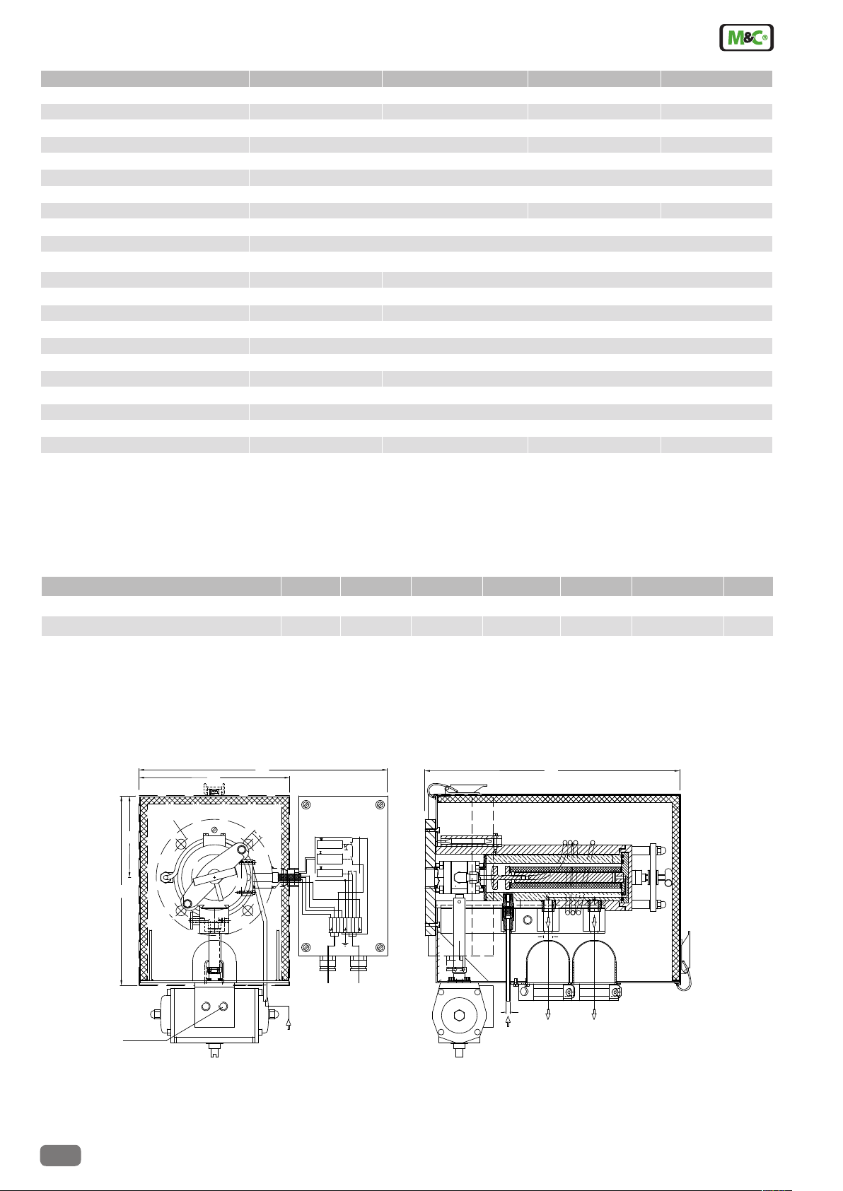
Dimensions
SP2000-H basic version with options (Examples)
260
110
207
130
340
14
T >+30°C
o
0-180°C
u
T <-30°C
Tset
2N1
53 4 6 87 9
L 'L
345
1/4"NPTi
Dimensions in mm
2.1
Alarm contact
Power
230V,50Hz
(115V,60Hz)
Actuator
pressure inlet
G 1/4" i
Blow back
(test gas)
M&C TechGroup Germany GmbH • Rehhecke 79 • 40885 Ratingen • Germany
info@mc-techgroup.com • www.mc-techgroup.com • Fon +49 2102 935-0 • Fax +49 2102 935-111
6
Test gas
(Blow back)
Sample gas
outlet *
Second sample
gas outlet
*Standard
Technical specications and illustrations are without
obligation, subject to modications. 10.04/06.06
Page 3

Basic versions and options (choice)
Basic executions Data sheet Version Part-No.
Basic execution, non-heated, without weather protection shield, material SS 316Ti SP2000 20 S 1000
Basic execution, heated to 0-180 °C ,with weather protection shield, material SS 316Ti SP2000-H 20 S 2000
Basic execution, heated to 0-180 °C, , with weather protection shield, material PTFE 2-1.1.3 SP2300-H 20 S 3000
Basic execution, heated to 0-180 °C, , with weather protection shield, material Titanium SP2400-H 20 S 3500
Options integrated in the gas sample probe (extract)
Power supply 115V/60Hz /115V 20 S 9030
Top of filter case with PTFE-rings and seals of PTFE 2-1.1.2 /7aT 20 S 9010
Second outlet for sample gas 1/4" NPTi /2x 20 S 9015
Back purge/calibration gas valve, opening pressure 0,7 bar, pipe 6 mm, blow back and test gas feeding via filter
chamber
Back purge/calibration gas valve for SP2400-H, opening pressure 0,7 bar, 1/4" NPTi, blow back and test gas feeding via filter chamber
Fiber glass filter element 0,1GF150, filter porosity 0,1 µm, sealing PTFE 2-1.1.2 /GF150 20 S 9020
Spec. filter housing lid and unscrewed cartridge incl. spun glass filling, sealing FPM, Novapress 2-1.1.2 /FW 20 S 9047
Spec. filter housing lid and unscrewed cartridge incl. spun glass filling for 320 °C, sealing graphit 2-1.1.2 /FW 320 20 S 9046
Electrical heating of the exernal filter to 0-320 °C 2-1.2.8 /H320 20 S 9021
Execution for max. 25 bar operating pressure, mounting flange DN50 PN25 /HP 20 S 9017
Gas pre-heater GVW1, material SS304 /GVW1 20 S 9058
Connection of the gas pre-heater to valve ”R” and to gas inlet /GVW 20 S 9062
PT00 sensor instead of the thermostat, without temp. controller /PT100 20 S 9025
Thermoelement FE-CuNi ( type J) instead of thermostat, without temp. controller /Fe-CuNi 20 S 9027
Thermoelement Ni-CrNi (type K) instead of thermostat, without temp. controller /Ni-CrNi 20 S 9028
Second PT100 sensor /2-PT100 20 S 9026
Execution with electrical safety separation according VDE106T101 in connection with thermostat /ST 20 S 9031
Steam heating, without controller and valves 2-1.2.10 /D 20 S 9033
Adapter flange size DN..PN6 or ANSI..150 lbs /DN 20 S 9004
Mounting fitting R2"a or 2"-NPTa instead of the mounting flange /SO1 20 S 9005
Integrated 2-way ball valve with lock function in the inlet 2-1.3.5/2-1.4.5 /VA 20 S 9050
Integrated 3-way ball valve with T-function in the inlet 2-1.3.5/2-1.4.5 /3VA 20 S 9325
Integrated 2-way ball valve with lock function in the inlet, up to 320 °C 2-1.3.5/2-1.4.5 /VA320 20 S 9053
Integrated 3-way ball valve with T-function in the inlet, up to 320 °C 2-1.3.5/2-1.4.5 /3VA320 20 S 9330
Pneumatic drive for ball valves VA and 3VA, 2 operating states 2-1.3.5/2-1.4.5 /MS1 20 S 9055
Pneumatic drive for valves VA 320°C and 3VA 320 °C, 2 operating states 2-1.3.5/2-1.4.5 /MS3 20 S 9056
Electrical actuating drive for ball valves VA and 3VA, 2 operating states, 230V/50Hz 2-1.4.10 /EA230 20 S 9342
Electrical actuating drive for ball valves VA and 3VA, 2 operating states, 115V/60Hz 2-1.4.10 /EA115 20 S 9342a
Electrical actuating drive for ball valves VA and 3VA, 2 operating states, 24V DC 2-1.4.10 /EA24 20 S 9342d
Filter housing lid for high flowrate with filter element 0,1GF /HF 20 S 9016
/R 20 S 9045
/R-Ti 20 S 9048
Basic version
207
Ø130
110
260
Technical specications and illustrations are without
obligation, subject to modications. 10.04/06.06
160
340
Ø14
345
To >+30°C
Tset
0-180°C
Tu <-30°C
21 5
34 6 87 9
N
Power
230V,50Hz
(115V,60Hz)
L 'L
Alarm contact
103
1/4"NPTi
Sample outlet
M&C TechGroup Germany GmbH • Rehhecke 79 • 40885 Ratingen • Germany
info@mc-techgroup.com • www.mc-techgroup.com • Fon +49 2102 935-0 • Fax +49 2102 935-111
2.1
Page 4

Options for basic versions
Short term SP2000 SP2000-H SP2300-H SP2400-H
/115V – X X X
/7aT X X – –
/2x X X X X
/R X X X X
/R-Ti X X X X
/GF150 X X X X
/FW X X – X
/FW 320 – X – X
/H320 – X – X
/HP X X – –
/GVW1 – X X X
/GVW – X X X
/PT100 – X X X
/FeCuNi – X X X
/Ni-CrNi – X X X
/2-PT100 – X X X
/ST – X X X
/D – X X X
/DN X X – –
/SO1 X X – X
/VA X X – –
/3VA X X – –
/VA320 – X – –
/3VA320 – X – –
/MS1 X X – –
/MS3 X X – –
/EA230 X X – –
/EA115 X X – –
/EA24 X X – –
/HF X X – –
– not possible
X possible
The above table does only indicate the possible options for the dierent probe types. This is no statement about the possible combinations of these options with each other in a probe
model. In case you are looking for several options to be combinated, please ask our sales team for technical advice.
2.1
M&C TechGroup Germany GmbH • Rehhecke 79 • 40885 Ratingen • Germany
info@mc-techgroup.com • www.mc-techgroup.com • Fon +49 2102 935-0 • Fax +49 2102 935-111
Technical specications and illustrations are without
obligation, subject to modications. 10.04/06.06
 Loading...