

Page 1
Operating Instructions
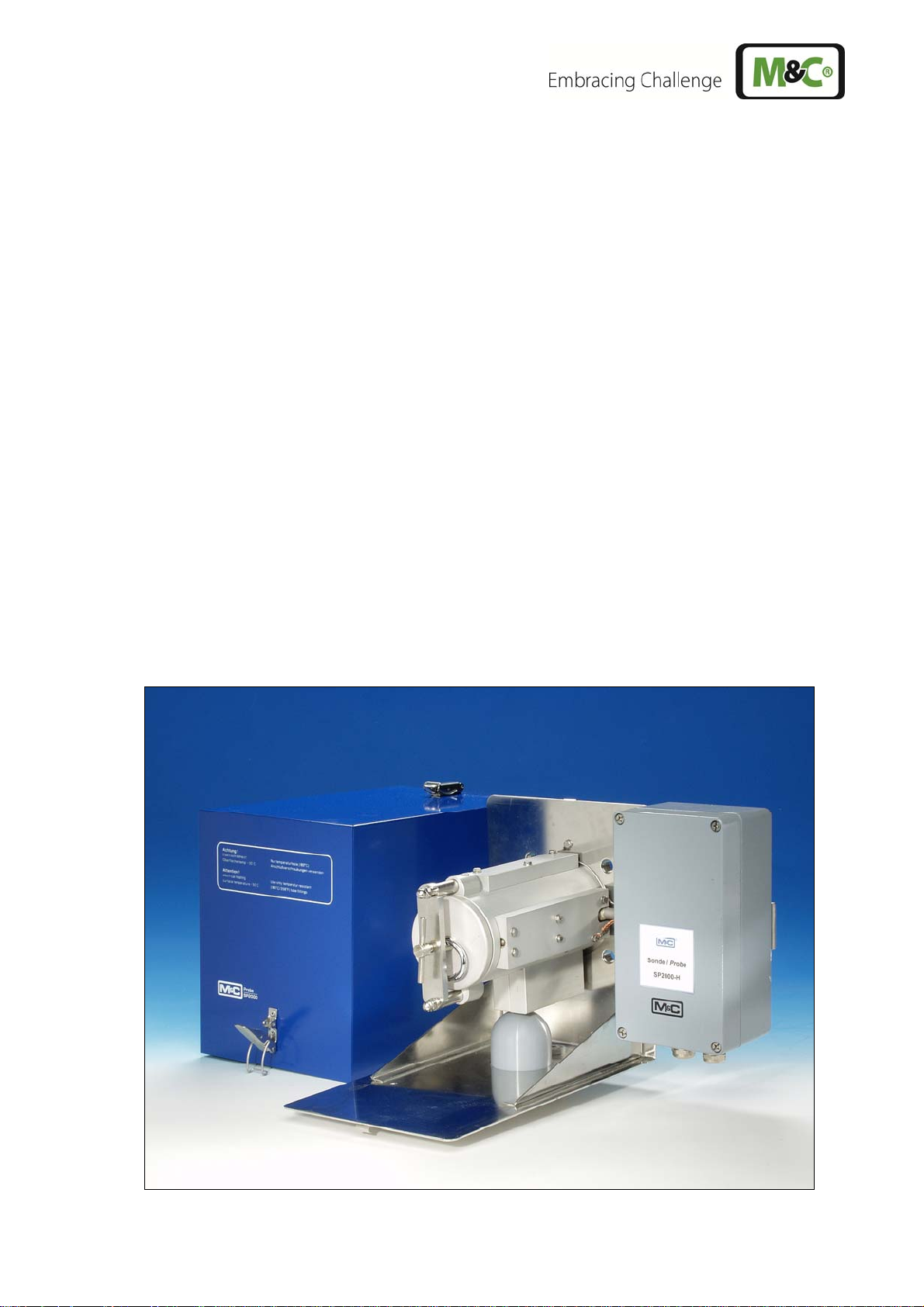
Gas Sample Probe Series SP®
Version SP2000, SP2000-H, SP2300-H, SP2400-H
serial number 10283 and higher
Gas sampling and gas conditioning technology 2-1.1-ME
Page 2

Contents
1 General information .................................................................................................................... 5
2 Declaration of conformity .......................................................................................................... 5
3 Safety instructions ...................................................................................................................... 6
4 Warranty ...................................................................................................................................... 6
5 Used terms and signal indications ............................................................................................ 7
6 Introduction ................................................................................................................................. 7
7 Serial numbers ............................................................................................................................ 8
8 Technical Data ............................................................................................................................. 9
9 Application .................................................................................................................................. 9
10 Description ................................................................................................................................ 10
11 Probe design of the heated version ........................................................................................ 11
11.1 Sample gas connection ...................................................................................................... 11
11.2 Temperature controller ....................................................................................................... 12
11.3 Sample tube and prefilter possibilities ................................................................................ 12
12 Receipt of goods and storage ................................................................................................. 14
13 Preparation for Installation ...................................................................................................... 15
14 Mounting .................................................................................................................................... 16
14.1 Check of the filter element ................................................................................................. 16
14.2 Mounting of the screwed connector at the sample outlet ................................................... 18
14.3 Mounting of probe with sample tube or prefilter ................................................................. 18
14.4 Mounting of sample line ..................................................................................................... 21
14.5 Connection of option test gas feeding or blow back line .................................................... 22
14.6 Connection option pneumatic drive MS1 or MS3 ............................................................... 23
15 Electrical connections .............................................................................................................. 23
15.1 Standard Version with Internal Capillary Tube Thermostat ................................................ 23
15.2 Version with PT100 or thermocouple (option) .................................................................... 24
16 Starting ...................................................................................................................................... 26
16.1 Gas sample probe SP2300-H ............................................................................................ 27
16.2 Option calibration gas feeding and blow back .................................................................... 27
16.2.1 Option check valve /R .................................................................................................. 27
16.2.2 Via 3/2 way ball valve /3VA ......................................................................................... 28
16.3 Option ball valve drives ...................................................................................................... 29
16.3.1 Option Pneumatic drive MS1 or MS3 when using a 2/2-way ball valve /VA ................ 29
16.3.2 Option Pneumatic drive MS1 or MS3 when using a 3/2-way ball valve /3VA .............. 30
16.3.3 Option Electrical ball valve drive .................................................................................. 31
16.4 Option solenoid valve units for blow back, test gas feeding and control of the
pneumatic drives ................................................................................................................ 31
16.4.1 Option drive unit 234B for the solenoid valve units ..................................................... 34
17 Maintenance .............................................................................................................................. 36
17.1 Changing filter element and checking sealings .................................................................. 37
17.2 change of the optional prefilter ........................................................................................... 38
17.3 Change of heating cartridge and thermostat ..................................................................... 38
18 Switching Off ............................................................................................................................. 41
19 Spare part list ............................................................................................................................ 41
20
Connection and mounting data ............................................................................................... 42
21 Appendix .................................................................................................................................... 43
2 Gas sampling and gas conditioning technology 2-1.1-ME
Page 3

List of illustrations
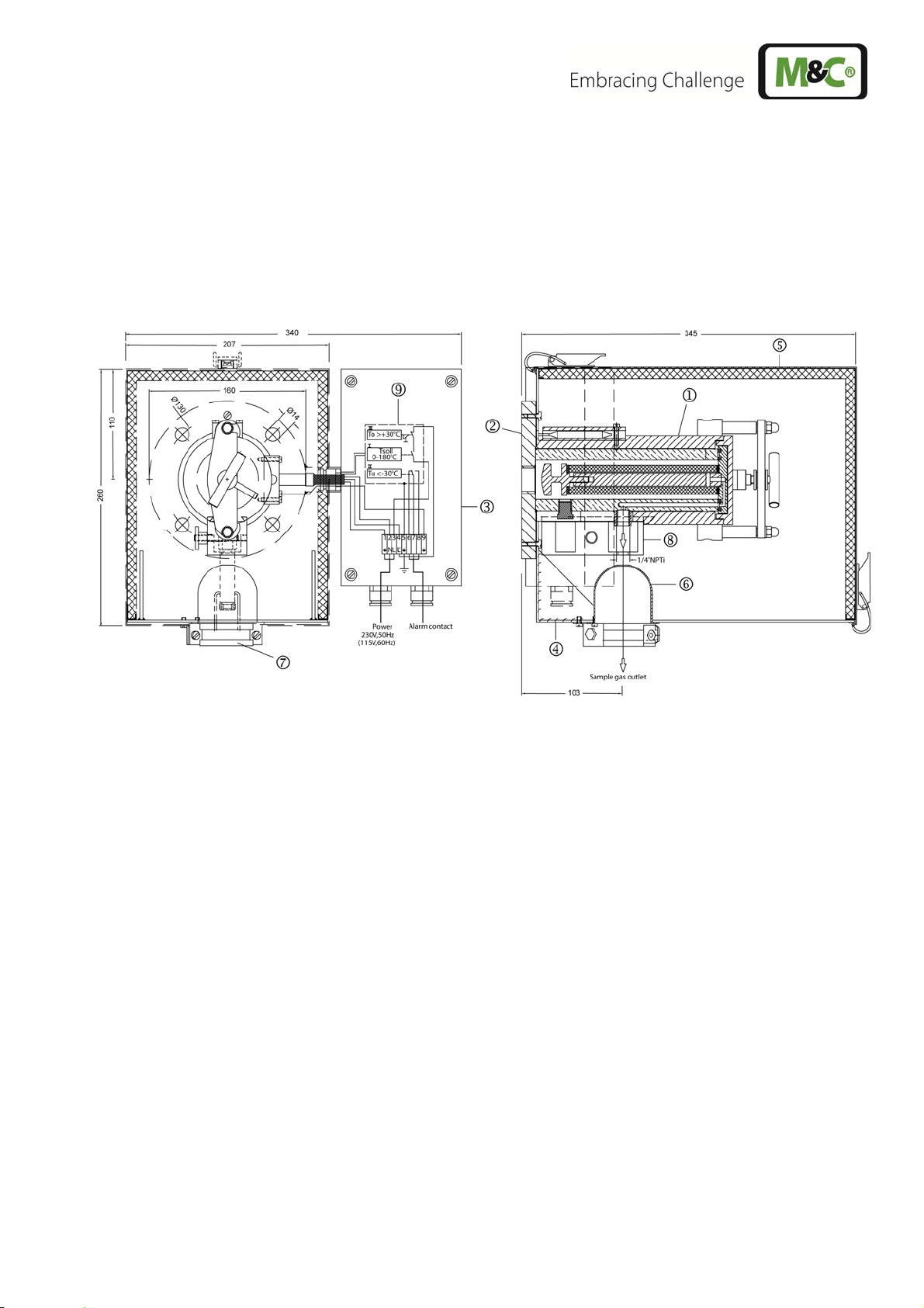
Figure 1 Design of basic version SP2000-H .................................................................................... 11
Figure 2 Mounting possibilities SP2000..., SP2300-H, SP2400-H ................................................... 15
Figure 3 Cross-sectional drawing SP2000-H ................................................................................... 16
Figure 4 Removing the new filter housing lid ................................................................................... 17
Figure 5 Mounting of screwed connector at sample outlet .............................................................. 18
Figure 6 Mounting of sample tube or prefilter .................................................................................. 20
Figure 7 Mounting of heated sample line ......................................................................................... 21
Figure 8 Connection test gas feeding or blow back line .................................................................. 22
Figure 9 Electrical connection for SP2000-H, SP2300-H and SP2400-H with thermostat
controller ............................................................................................................................ 24
Figure 10 Electrical connection of external temperature controller e.g. 70304G ............................. 25
Figure 11 Electrical connection electronic controller 70304G ............................................................ 26
Figure 12 Calibration gas feeding ...................................................................................................... 28
Figure 13 Pneumatic drive for 2/2-way ball valve .............................................................................. 29
Figure 14 Pneumatischer Antrieb für 3/2-Wege Kugelhahn .............................................................. 30
Figure 15 Electrical connection for electrical ball valve drive ............................................................ 31
Figure 16 Connections solenoid valve unit 2 ..................................................................................... 32
Figure 17 Connections solenoid valve unit 3 ..................................................................................... 33
Figure 18 Wiring plan of control unit 234B ......................................................................................... 36
Figure 19 Filter elements and gaskets ............................................................................................... 37
Figure 20 Position of Thermostat and heating cartridge .................................................................... 39
Figure 21 Position of fixing screws of connection box, thermostat sensor and heating cartridge
carrier plate ........................................................................................................................ 39
Figure 22 Dismounted electrical connection box with heating cartridge and thermostat sensor ....... 40
Figure 23 Adjustment of the mechanical stop at the thermostat controller ........................................ 40
Figure 24 SP2000-H basic version .................................................................................................... 44
Figure 25 SP2000-H with options ...................................................................................................... 45
Figure 26 High temperature tube aluminium oxide AO ...................................................................... 46
Figure 27 Heated sample tubes SP30-H... ........................................................................................ 47
Figure 28 Test gas feeding and blow back possibilities ..................................................................... 49
Figure 29 SP2000-H/3VA/MS-NC-B .................................................................................................. 50
Figure 30 SP2000-H/3VA/MS-NC-C .................................................................................................. 51
Figure 31 SP2000-H/3VA/MS-NO-B .................................................................................................. 52
Figure 32 SP2000-H/3VA/MS-NO-C .................................................................................................. 53
2-1.1-ME Gas sampling and gas conditioning technology 3
Page 4

j
Dear customer,
we have made up this operating manual in such a way that all necessary information about the product can be found and understood quickly and easily.
Should you still have any question, please do not hesitate to contact M&C directly or go through your
appointed dealer. Respective contact addresses are to be found in the annexe to this operating manual.
Please also contact our homepage www.mc-techgroup.com for further information about our prod-
ucts. There, you can read or download the data sheets and operating manuals of all M&C products as
well as further information in German, English and French.
This Operating Manual does not claim completeness and may be sub-
ect to technical modifications.
© 10/2001 M&C TechGroup Germany GmbH. Reproduction of this
document or its content is not allowed without permission from M&C.
®
is a registered trade mark.
SP
5th Edition: 09/2012
4 Gas sampling and gas conditioning technology 2-1.1-ME
Page 5

Head Office
M&C TechGroup Germany GmbH Rehhecke 79 40885 Ratingen Germany
Telephone: 02102 / 935 - 0
Fax: 02102 / 935 - 111
E - mail: info@mc-techgroup.com
www.mc-techgroup.com
1 GENERAL INFORMATION
The product described in this operating manual has been examined before delivery and left our works
in perfect condition related to safety regulations. In order to keep this condition and to guarantee a
safe operation, it is important to heed the notes and prescriptions made in this operating manual. Furthermore, attention must be paid to appropriate transportation, correct storage, as well as professional
installation and maintenance work.
All necessary information a skilled staff will need for appropriate use of this product are given in this
operating manual.
2 DECLARATION OF CONFORMITY
CE - Certification
The product described in this operating manual complies with the following EC directives:
EMV-Instruction
The requirements of the EC directive 2004/108/EC “Electromagnetic compatibility“ are met.
Low Voltage Directive
The requirement of the EC directive 2006/95/EC “Low Voltage Directive“ are met.
The compliance with this EC directive has been examined according to DIN EN 61010.
Declaration of conformity
The EU Declaration of conformity can be downloaded from the M&C homepage or directly requested
from M&C.
2-1.1-ME Gas sampling and gas conditioning technology 5
Page 6

3 SAFETY INSTRUCTIONS
Please take care of the following basic safety procedures when mounting, starting up or operating this equipment:
Read this operating manual before starting up and use of the equipment. The information and warnings given in this operating manual must be heeded.
Any work on electrical equipment is only to be carried out by trained specialists as per the regulations
currently in force.
Attention must be paid to the requirements of VDE 0100 (IEC 364) when setting high-power electrical
units with nominal voltages of up to 1000 V, together with the associated standards and stipulations.
Check the details on the type plate to ensure that the equipment is connected to the correct mains
voltage.
Protection against touching dangerously high electrical voltages:
Before opening the equipment, it must be switched off and hold no voltages. This also applies to any
external control circuits that are connected.
The device is only to be used within the permitted range of temperatures and pressures.
Check that the location is weather-protected. It should not be subject to either direct rain or moisture.
The equipment must not be used in hazardous areas.
Installation, maintenance, monitoring and any repairs may only be done by authorized personnel with
respect to the relevant stipulations.
4 WARRANTY
If the equipment fails, please contact M&C directly or else go through your M&C authorised dealer.
We offer a one year warranty as of the day of delivery as per our normal terms and conditions of sale,
and assuming technically correct operation of the unit. Consumables are hereby excluded. The terms
of the warranty cover repair at the factory at no cost or the replacement at no cost of the equipment
free ex user location. Reshipments must be send in a sufficient and proper protective packaging.
6 Gas sampling and gas conditioning technology 2-1.1-ME
Page 7

5 USED TERMS AND SIGNAL INDICATIONS
This means that death, severe physical injuries and/or important
material damages will occur in case the respective safety measures
DANGER!
WARNING!
CARE!
CARE! Without the warning triangle means that a material damage may
ATTENTION!
NOTE!
SKILLED STAFF
are not fulfilled.
This means that death, severe physical injuries and/or important
material damages may occur in case the respective safety
measures are not fulfilled.
This means that minor physical injuries may occur in case the re-
spective safety measures are not fulfilled.
occur in case the respective safety measures are not met.
This means that an unintentional situation or an unintentional status
may occur in case the respective note is not respected.
These are important information about the product or parts of the
operating manual which require user’s attention.
These are persons with necessary qualification who are familiar with
installation, use and maintenance of the product.
6 INTRODUCTION
2-1.1-ME Gas sampling and gas conditioning technology 7
Page 8

Major problems of the extractive continuous gas analysis are the materials contained in the sample
gas e.g. dust, water vapour and also gas components forming corrosive acids with condensing water
vapour.
In order to realize an easy-to-maintain measurement the dust has to be separated without condensation of water vapour. This prevents „baking“ of dust and water and the possible acid formation. This
way a blockage of filters and connected line is prevented and the probe material in contact with the
gas will not be affected.
The solution are heated M&C sample probes like e.g. probes of the series SP2000... This probes
guarantee a minimum of maintenance work if correctly adapted to the process conditions. At the con-
tinuous gas sampling for analytical measurements with M&C gas sample probes a fine dust filtration
already happens at the sample point. Hereby already a majority of necessary maintenance work at
analyser systems is prevented.
Basically, the quantity of sampled gas should be kept to a necessary minimum to guarantee a minimum of maintenance work and a maximum of availability. This is made possible thanks to optimised
downstream gas conditioning using M&C components.
7 SERIAL NUMBERS
The nameplates bearing the serial number are located on the side of the electrical connection box.
NOTE!
Always quote the device's serial number when making enquiries and ordering replacement parts.
8 Gas sampling and gas conditioning technology 2-1.1-ME
Page 9

8 TECHNICAL DATA
Gas sample probe type SP2000 SP2000-H SP2300-H SP2400-H
Part no. 20S1000 20S2000 20S3000 20S3500
Weather protection shield no yes yes yes
Protection class terminal box IP54 EN60529
Material filter housing Stainless steel SS316/316Ti* PTFE Titanium
Sealing material FPM* /7aT** = PTFE -H320/C** = Graphite
Probe flange sealing material Novapress
Insitu probe tube / prefilter Optional
Sample pressure max. 0,4-6 bar* abs., /7aT**= 2 bar abs.,
/HP** = 25 bar abs.
Ambient temperature 20 °C to +180 °C -20 °C to +60 °C*;
/PT100, /Fe-CuNi, /Ni-CrNi** = -20°C to +80°C
Filter chamber volume 120 cm3
Filter porosity S-2K150= ceramic*, 2micron, /F-0, 1GF150= glass fibre**, 0,1 micron,
/F-3SS150= stainless steel**, 3 micron, /FW= spun glass**
Thermostat, temperature adjustment
Ready for operation after 40min -H320/C** = after 60min
Low temperature alarm contact* contact rating: 250V, 3A~, 0,25A= alarm point: ∆T 30°C
Sample gas outlet cnnection 1x 1/4“ NPTi* tube connection** ø 6, 8 or 10mm
Backflush/Test gas connection
Power supply
Electrical connections Terminals max. 4mm2, 2 x cable gland PG 13,5
Electrical equipment standard
Mounting flange DN65 PN6, form B >DN or ANSI possible** /HP** = DN50 PN25
Mounting flange material SS316Ti PTFE Titanium
Weight 7 kg* 15,4 kg* 15,4 kg* 14,5kg*
* = Standard
** = Optional
0-180°C* -H320/C**= 0-320°C /PT100** /Fe-CuNi** /Ni-
CrNi**
-H320/C**= tube connection 6mm or 8mm*
1/4“ NPTi* /R**, -H320/C**= tube ø 6 mm
230V 50/60 Hz, 800W /115V** = 115V 60Hz, 800W (fuse
protection 10A)
EN 61010, EN 60519-1
Differential pressure and T90-time at different flow rates
P and T90 at flow of
P with new filter element
S-2K 150/F-0,1GF150
P with new filter element
F-3SS150
T90-time without sample
tube/prefilter
100 200 500 1000 1500 3000 (only /HF) Nl/h
0,007 0,011 0,020 0,058 0,135 0,240/0,225 bar
0,006 0,012 0,040 0,110 0,215 0,405 bar
6,0 3,5 1,0 <0,5 <0,5 <0,5 sec.
2 bar abs. 0,4-6 bar abs.
9 APPLICATION
The M&C gas sample probes type SP2000..., SP2300-H and SP2400-H are used for continuous ex-
traction of gases from dust laden, high-temperature and/or humid processes.
2-1.1-ME Gas sampling and gas conditioning technology 9
Page 10

10 DESCRIPTION
The sample probes are designed for easy installation, reliable and flexible operation and trouble-free
maintenance. Depending on the problem, different sample tubes or prefilters (see data sheet 2-1.1.0.6
and 2-1.1.0.8) are screwed into the thread (G3/4”) in the mounting flange. This equipment is not included in the scope of delivery of the probe.
The large-surface ceramic deep filter element (fibre glass or glass wadding fillings are also available)
is placed in a housing with small dead volume outside the process area. The probes are designed so
that no tools are necessary for changing the filter element, the sample line needs not to be dismounted and no contamination on the clean gas side will occur. Cleaning or back purging of the sample tube
is possible from outside. Due to the special execution of the heating element of the SP2000-H,
SP2300-H and SP2400-H (with protection cover), the complete filter housing including mounting
flange is heated, adjustable up to 180°C (version H320/C up to 320°C), so that a safe operation without shortfall below the dew point in the out-of-process area is guaranteed. The temperature adjustment of the standard version is made via an integrated capillary sensor thermostate with exess temperature limiter and alarm function in compact configuration. Calibration gas feeding and comparison
sampling at the probe are possible.
Depending on the gas composition, it may be possible that the standard material of the probe body
(stainless steel 1.4404) is not sufficient with respect to ist corrosion resistance. For this case, the
SP2300-H of PTFE is available or alternatively for a heating above 180°C the SP2400-H out of Titane.
The following filter elements are available:
Filter elements Type Porosity Material
Filter element S-2K 150 2µm
Filter element S-3G 150 3µm Glass
Filter element S-3SS 150 3µm Stainless steel SS316
Filter element S-0,1GF 150 0,1µm Glass fiber
Filter element FW -------- Spun glass
* = Standard
The following sealing agents are applied:
Material Type Max. temperature
Viton Standard max. 180°C
PTFE Type /7aT max. 180°C
Graphite Type -H320/C max. 320°C
The following types of partial filter heating and regulation are possible:
Type Version
-H
/PT100
/Fe-CuNi
/Ni-CrNi
/D
* = Standard
Electrical heating and control with incorporated capillary thermostat*
Electical heating and control with external electronic temperature controller
Steam heating, not controlled
Ceramic*
10 Gas sampling and gas conditioning technology 2-1.1-ME
Page 11
11 PROBE DESIGN OF THE HEATED VERSION
A complete gas sample probe consists of the heated filter part and a sample tube or prefilter. The filter
housing with its all-round heating element forms a unit with the standard mounting flange DN65
PN6 and the laterally mounted electrical connection box .
The heat-insulated shield is mounted on the stainless steel angle sheet which is mounted on the
mounting flange. It is secured with 2 pressure clamps. The cover ensures a uniform distribution of heat
over the probe heater and at the same time serves as protection against weather and accidental contact.
Figure 1 Design of basic version SP2000-H
11.1 SAMPLE GAS CONNECTION
The connecting clamp for attaching heated M&C sample lines with external dimensions of between
40mm and 50mm is located at the aperture on the underside of the angle sheet, which is closed with a
silicon lid . The clamp is mounted on an adjustable mounting bracket which allows adjustment for
various sample line diameters.
The standard probe's sample gas outlet connection has a ¼" NPT internal thread to which the customer must connect a suitable size of temperature resistant and threaded connector to connect the
sample line in a gas tight manner. These connectors can be supplied by M&C.
In the high-temperature version -H320/C..., the sample gas outlet connection is fitted with a welded 6
mm threaded pipe connection (optional 8mm).
After the threaded pipe connector and sample line have been mounted, the sample gas outlet connection is enclosed in special heat-conducting jaws in order to avoid temperature failures in the critical
connection areas. The size of the heat-conducting jaws allows connection joints up to an external pipe
dimension of 10mm.
2-1.1-ME Gas sampling and gas conditioning technology 11
Page 12

1)
11.2 TEMPERATURE CONTROLLER
In standard version -H, or with option –H320/C temperature control is ensured by way of the capillary
tube thermostat which is built into the connection box and which has a regulation range between 0°C
to 180°C (-H) or 0°C to 320°C (-H320/C). Rated values can be set to a maximum 180°C resp. 320°C.
The temperature has an excess temperature limiter which permanently switches off the heating if the
set temperature is exceeded by 30°C. The heating can be switched back on again by pressing the
green RESET-button which is located below the aperture in the thermostats mounting.
The thermostat has a temperature failure alarm which activates a contact if the temperature falls 30°C
below the set temperature. This status alarm is located on the terminal strip as a potential-free switch
over contact.
If temperature control is to be achieved using external electronic equipment, a PT100 (a max. of two
can be built in) or an Fe-CuNi resp. Ni-CrNi thermoelement is provided as a temperature sensor.
M&C also supplies suitable temperature controller, e.g. Type 70304G (see data sheet 2-5.1) which
also can be mounted directly at the gas sample probe (max. ambient temperature +45°C).
11.3 SAMPLE TUBE AND PREFILTER POSSIBILITIES
Depending on the process gas temperature and composition, probe tubes made of different materials
are used with ¾" connections.
Sample tube
Type
SP2000/PV 20S9070 90 PVDF/ PTFE-GV 1000 1500 25/21
SP32** 20S9280 90 PVDF/ PTFE-GV 800 800 50/44
SP2000/T 20S9083 160 PTFE/ PTFE-GV 500 500 25/15
SP2000/Ti 20S9075 400 Titanium 1000 2500 25/22
SP210/SS 02S9200 600 SS316Ti 1000 2000 12/10
SP2000/SS 20S9065 600 SS316Ti 1000 2500 25/22
SP2000/SS-Vm 20S9067 600 SS316Ti 1000 2500 25/06
SP2000/HC 20S9090 900 Hastelloy C4 1000 2500 25/22
SP2000/KA 20S9080 1300 Kanthal / SS316Ti 1000 1500 27/20
SP2000/IN 20S9077 1100 Inconel 1000 2000 25/22
SP2000/CR-2* 20S9098 1400 Cr AL2 O3 / Hastelloy C4 900 900 22,5/13
SP2000/CR-20* 20S9099 1400 Cr AL2 O3 / Hastelloy C4 1200 1200 22,5/13
SP2000/AO + ↓ 20S9385 1800 Aluminiumoxide 2) / 1000 1500 24/18
Adapter 20S9395 (600) / SS316Ti
Adapter 20S9397 (900) / Hastelloy C4
* Sample tube with support adapter. Max.Temperature concern the area of the support adapter on approx. 200 mm length depend on material 600/900 °C.
** For gas sampling downstream wet scrubbers for droplet separation
1)
standard
2)
Please pay attention to the characteristic feature of ceramic in case of high and changing temperatures!
Other materials or executions on request.
Part no. Temperature
max. °C
Material
tube / connection part
Length
mm
Length
max. mm
Tube ø
o/i „d1“ mm
For more information about sample tubes see data sheet 2-1.1.0.6
To prevent condensation between sample point and heated gas sample probe or in case of condensation in the area of the connection piece heated sample tubes made of stainless steel with flange
connection DN65 PN6 are used.
12 Gas sampling and gas conditioning technology 2-1.1-ME
Page 13

Type Max. process temperature Length max. Tube ø o. Temperature sensor
SP-30H1.1, heating max. 320°C bis max. 550 °C
SP-30H1.1V, heating max. 320°C bis max. 550 °C
SP30-H2, heating max. 320°C bis max. 550 °C
SP35-H1.1, heating max. 320°C bis max. 550 °C 0,175 m ø 42,2mm Fe-CuNi
SP35-H2, heating max. 320°C bis max. 550 °C 0,175 m ø 42,2mm PT100
* = standard
2,0 m *
2,0 m *
2,0 m *
ø 42,2mm Fe-CuNi
ø 42,2mm Fe-CuNi
ø 42,2mm PT100
For more information about heated sample tubes see data sheet 2-1.9.5
In case of heavier dust loading of the process gas, we recommend using a prefilter under all circumstances in order to prolong service life. This can be supplied with or without dead volume displacer
depending on the response times required. These filters can be screwed directly into the probe flange
or via extension tubes fitted with volume displacers.
2-1.1-ME Gas sampling and gas conditioning technology 13
Page 14

The following prefilters can be selected :
Prefilter
Type
SP2000/20SS 150 20S9160 600 SS316/316Ti 20 2-10
SP2000/V20 20S9085 600 SS316/316Ti 2 2-10
SP2000/V20-0 20S9105 600 SS316/316Ti 2 2-10 X 220 46 G 3/4"a
SP2000/V20/HC 20S9095 900 Hastelloy-C 2 2-10
SP2000/V20-0/HC 20S9115 900 Hastelloy-C 2 2-10 X 220 46 G 3/4"a
SP2000/V20-T 20S9315 200 PTFE / SS316Ti 3 > 10
SP2000/V20-2 20S9125 600 SS316/316Ti 2 > 10
SP2000/V20-1 20S9145 600 SS316/316Ti 2 > 10 X 520 60 G 3/4"a
SP2000/V20-2/HC 20S9135 900 Hastelloy-C 2 > 10
SP2000/V20-1/HC 20S9155 900 Hastelloy-C 2 > 10 X 520 60 G 3/4"a
SP2000/V20-41) 20S9290 600 SS316/316Ti 2 2-10
SP2000/V20-31) 20S9300 600 SS316/316Ti 2 2-10 X
SP2000/V20-5 20S9127 500 SS316/316Ti 3 2-10
SP2000/V20-6 20S9128 500 SS316/316Ti 3 > 10
SP2000/V12-1 20S9500 1000
SP2000/V12-3 20S9510 1000
SP2000/V12-2 20S9505 1000
SP2000/V12-1/SS2) 20S9525 600
SP2000/V12-3/SS3) 20S9535 600
SP2000/V12-2/SS3) 20S9530 600
SP2000/V12-1/IC2) 20S9540 1000
SP2000/V12-3/IC3) 20S9550 1000
SP2000/V12-2/IC3) 20S9545 1000
1)
Prefilter V20-3, V20-4 optional up to 1000 mm length available.
2)
With protection tube V12-1.
3)
With protection tube V12-2/3.
4)
Prefilter with special construction for efficient back purge.
5)
Please pay attention to the characteristic feature of ceramic in case of high and changing temperatures!
Part no.
Temp.
max.
°C
Material
filter / connection
5)
Keramik
SS316Ti
Keramik
SS316Ti
Keramik
SS316Ti
Keramik
SS316Ti
Keramik
SS316Ti
Keramik
SS316Ti
Keramik
Incoloy-SS316Ti
Keramik
Incoloy-SS316Ti
Keramik
Incoloy-SS316Ti
/
5)
/
5)
/
5)
/
5)
/
5)
/
5)
/
5)
/
5)
/
Filter
porosity
µm
1 > 10
1 > 10 optional 1000 60
2 > 10 optional 1000 60
1 > 10
1 > 10 optional 1000 60
2 > 10 optional 1000 60
1 > 10
1 > 10 optional 1000 60
2 > 10 optional 1000 60
Dust
content
3
g/m
Inside
volume
displacer
Length
mm
150 31 ø 25
220 46 G 3/4"a
220 46 G 3/4"a
400 65 G 3/4"a
520 60 G 3/4"a
520 60 G 3/4"a
1)
300 31 G 3/4"a
1)
300 31 G 3/4"a
220 50 G 3/4"a
520 60 G 3/4"a
500 40
500 40
500 40
Filter
ø mm
Connection
DN65
PN6
DN65
PN6
DN65
PN6
DN65
PN6
DN100
PN6
DN100
PN6
DN65
PN6
DN100
PN6
DN100
PN6
For more information about prefilters see data sheet 2-1.1.0.8
12 RECEIPT OF GOODS AND STORAGE
The gas sample probe and any special accessories should be removed carefully from the packag-
ing and checked immediately for completeness against the delivery note.
Check the goods for any damage incurred during transport and if necessary inform your transport
insurer of any damage.
The gas sample probe is normally delivered in two packaging units:
1. The gas sample probe with the screws, nuts and flange seal required for mounting.
2. Sample tube or prefilter, if applicable with extension tube.
14 Gas sampling and gas conditioning technology 2-1.1-ME
Page 15
The equipment should be stored in a protected, frost-free room!
NOTE!
13 PREPARATION FOR INSTALLATION
Select the optimal sampling point in accordance with the generally applicable guidelines or consult
the competent persons.
Locate the sampling point in such a way that there is adequate space for inserting and removing
the probe and pay attention to the insertion length of the probe tube.
Make certain that the probe is easily accessible so that you can carry out any subsequent mainte-
nance work without trouble.
Locate the probe connections in such a way that the connections' temperature is always above the
acid dew point in order to avoid corrosion and blockage problems. If this is not possible, a heated
SP35/SP30 probe tube is recommended for cold connections.
If the ambient temperature in the area of the connections is >80°C as a result of radiated heat, then
a radiated-heat deflector must be mounted to protect the probe.
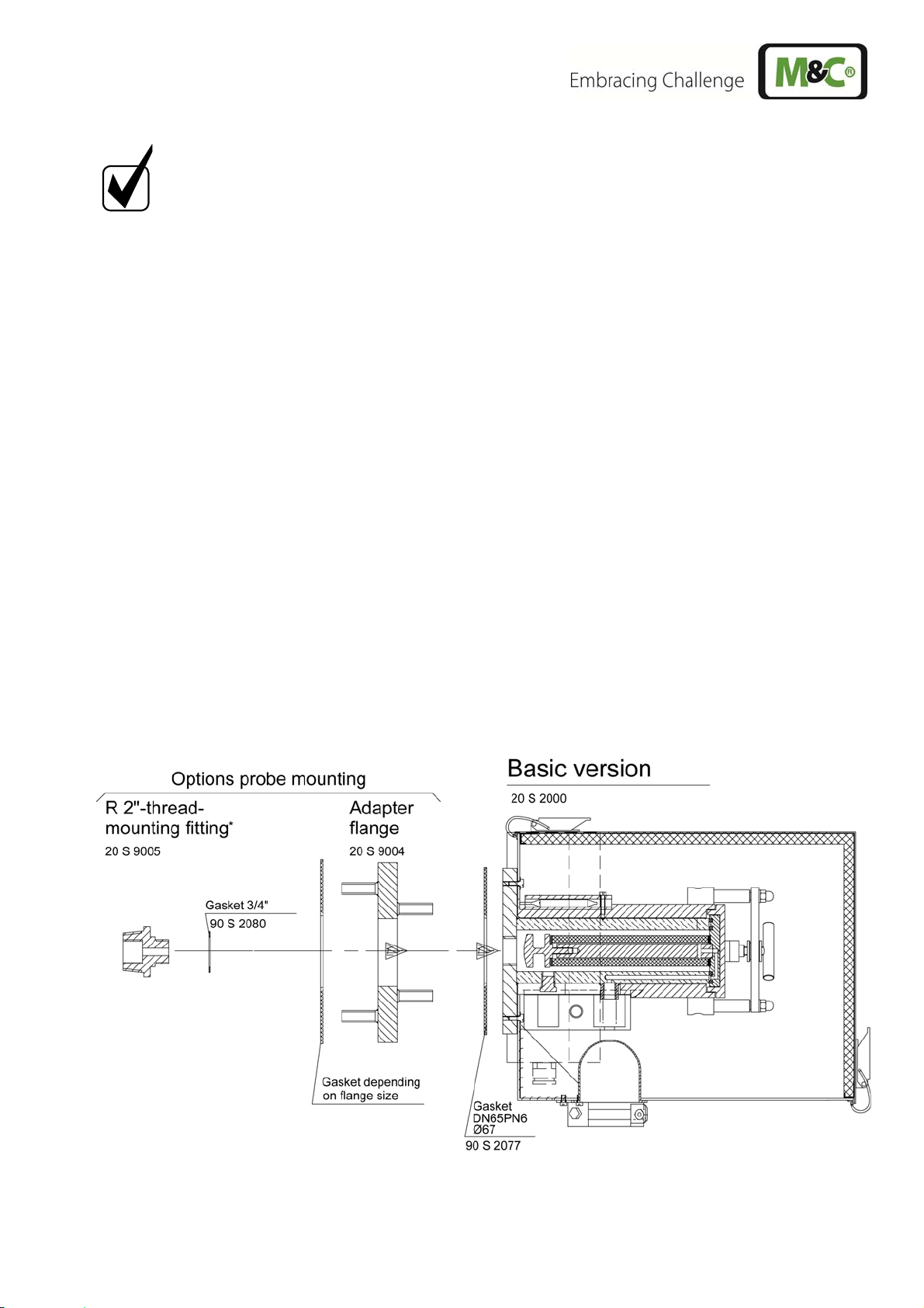
The connection's mounting flange connection should comply with DN65 PN6. If other connection
sizes are required, a special adapter flange /S010 can be supplied as an option. Instead of flange
connection mounting, the probe can also be mounted using an R2" adapter on a corresponding
threaded sleeve connection. This adapter can be supplied. The necessary minimum flange size
and the minimum connection diameter depends on the diameter of the probe tube or prefilter used.
Figure 2 Mounting possibilities SP2000..., SP2300-H, SP2400-H
2-1.1-ME Gas sampling and gas conditioning technology 15
Page 16
Before mounting, the probe must be adjusted to the existing operating conditions.
The existing operational parameters are to be checked accordingly prior to commencing
mounting work.
Low-excess pressure situation
Process temperature
Dust loading
Dust composition – grain size
Gas composition
Parameters to be measured, e.g. O2, CO, SO2,
,..,
NO
X
Necessary gas flow
Necessary T90-time
mbar bar
°C, Min. °C Max.
g/m³
µm
corrosive toxic explosive
Vol.% mg/Nm³ ppm
l/hr, Min. l/hr, Max.
s
14 MOUNTING
M&C SP2000 probes are designed for stationary use and if properly selected and mounted a long
service life and minimum maintenance are guaranteed.
It is advisable to mount the probe in an operational position which is at a 10% inclination to the process.
14.1 CHECK OF THE FILTER ELEMENT
Before starting the filter element has to be checked for tight fit.
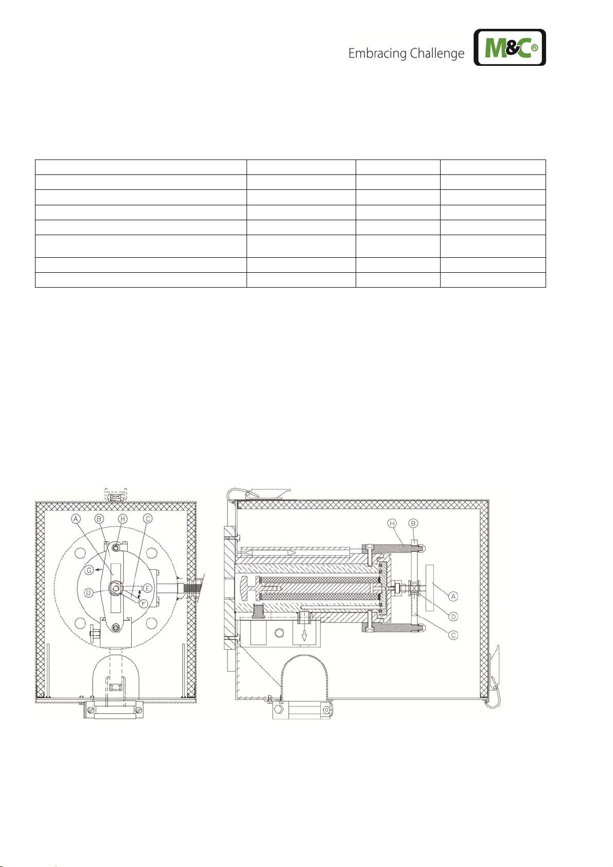
Figure 3 Cross-sectional drawing SP2000-H
Removing the filter housing lid to check or change the filter element has to be done as follows :
16 Gas sampling and gas conditioning technology 2-1.1-ME
Page 17

Remove the probe's protection shield after opening the two clamping devices;
Turn toggle screw „A“ approx. 1 turn counter-clockwise, that the filter housing lid will lift up;
Turn handle „C“ in position „E“;
Turn clamp „B“ counter-clockwise in direction „G“;
Take toggle screw „A“ and pull out the filter housing lid;
Check tight fit of filter element and tighten it if necessary (hand tight) or change filter element and
corresponding sealings;
When working during operation:
WARNING!
High surface temperatures!
Touching the surfaces can result in burns. Wear protective gloves
and any unauthorized access to the probe must be made impossible !
Push in the filter housing lid into the filter area;
Turn clamp „B“ clockwise and turn with the handle „C“ the ringsscrew „D“ in position „E“, that the
clamp „B“ will latch into the ringscrew „D“ and the threaded bolt „H“. It could be neccessary to move
the filter housing lid a little bit forward and backward;
Turn handle „C“ in position „F“ and fasten the filter housing lid by turning the toggle screw „A“
clockwise by hand.
The following pictures should explain the above mentioned steps.
Figure 4 Removing the new filter housing lid
2-1.1-ME Gas sampling and gas conditioning technology 17
Page 18

14.2 MOUNTING OF THE SCREWED CONNECTOR AT THE SAMPLE OUTLET
Remove heat conducting jaws at the sample outlet after loosening the knurled nut .
Figure 5 Mounting of screwed connector at sample outlet
In order to connect the sample line, screw in a suitably sized threaded connector with a ¼"-NPT
connecting thread using PTFE sealing tape.
For option second sample outlet SP2000/2x screw in two suitably sized threaded connectors with a
¼"-NPTa.
For option high heating -H320/C a 6mm pipe socket is welded on and a tube connector for 6mm
tube connection (optional 8mm) is supplied.
Remount heat conducting jaws and tighten knurled nut.
ATTENTION!
CARE!
Check tightness of the tube connections!
Never operate probe without heat conducting jaws because of the resulting cold bridge blocking of connector and line is to be expected !
14.3 MOUNTING OF PROBE WITH SAMPLE TUBE OR PREFILTER
Basically it is advantageous if the probe is built into the process with a lower downward inclination.
This mounting position is absolutely necessary if the SP32 sample tube is used for sampling e.g. after
wet scrubbers, so that separated liquid drops can flow back to process.
18 Gas sampling and gas conditioning technology 2-1.1-ME
Page 19

A preferred mounting position is to have the probe with its sample gas outlet
pointing downwards, although this is not absolutely necessary for perfect
functioning.
NOTE!
Insert flange seal (Fig. 6) between sampling flange and probe flange.
If the heated probe tube type SP30/35 or the ceramic prefilter type V12 is used, then the probe is to
be screwed to their flange (Fig. 6)(with welded threaded bolt). First insert the flange seal between the two flanges.
If the probe connection does not correspond to the standard flange connection DN65 PN6, then the
optionally supplied adapter flange (Fig. 2 and 6) should be mounted to the probe in the same way.
For high pressure version /HP a flange ist standardmäßig ein Flansch DN50 PN25 vorhanden
Screw either the probe tube or prefilter (Fig. 6) with thread G3/4”o directly or using an extension
tube with the ¾" flat gasket into the ¾" inner thread of the flange of the probe and tighten.
Insert sample tube or prefilter of the complete probe unit into the connection piece and screw
probe at the connection piece using the screws, spring rings and nuts supplied.
2-1.1-ME Gas sampling and gas conditioning technology 19
Page 20

Figure 6 Mounting of sample tube or prefilter
20 Gas sampling and gas conditioning technology 2-1.1-ME
Page 21

14.4 MOUNTING OF SAMPLE LINE
Open sample line mounting bracket .
Push end of the sample line into silicone cap in the bottom of the angle bracket.
Depending on type of heated sample line insert stainless steel pipe end with or without PTFE line
through hole in the silicone cap .
Figure 7 Mounting of heated sample line
Connect stainless steel connection piece or interchangeable PTFE tube at the fitting in the sam-
ple gas outlet of the probe. For this remove union nut with ferrule and cutting ring and put it in right
order and direction on the stainless steel connection piece or the PTFE tube.
ATTENTION!
If a PTFE tube is used as sample line, an insert must under all circumstances be inserted in the end of the tube in order to prevent the tube being pressed together.
Put connection piece or tube end into the fitting in the sample gas outlet of the probe and tighten
the union nut by hand.
2-1.1-ME Gas sampling and gas conditioning technology 21
Page 22

The temperature-resistant, stainless steel connectors supplied by M&C have a double ferrule sys-
tem to ensure reliable sealing. After tightening the nuts of these connectors by hand, they should
then be tightened exactly 1¼ of a turn using a flat spanner and are then properly mounted.
Close mounting bracket . In case of larger sample line diameters, it may be necessary for the
central mounting of the sample line to loosen the two screws and move the small mounting angle
of the mounting bracket and then re-tighten them.
Now place the heat conducting jaws around the sample gas connection in the retaining slot and
fix with the knurled nut .
CARE!
Never operate probe without heat conducting jaws because of the resulting cold bridge blocking of connector and line is to be expected !
14.5 CONNECTION OF OPTION TEST GAS FEEDING OR BLOW BACK LINE
When using the options /R or 3-way ball valve option /3VA or /3VA320 , the corresponding
tubes for test gas feeding or blow back are connected by means of a tube connection on the respective 6mm tube socket below the probe housing.
Figure 8 Connection test gas feeding or blow back line
With option -H320/C it is possible to feed test gas via the standard connection for a 6mm tube that
is equipped with a blind cap for the measuring operation. It is placed directly below the heat conducting jaws. For the connection of the calibration gas line, the blind cap must be removed. By
means of the union nut that is attached to the consignment, the calibration gas line can be connected.
ATTENTION!
22 Gas sampling and gas conditioning technology 2-1.1-ME
After the test gas feeding being finished, the connection must be shut
again with the blind cap because otherwise this connection would aspirate secondary air and falsify the measuring result !
Page 23

Optionally, the test gas feeding or back purging can be effected via a check valve -H320/R. The
check valve is mounted in the area of the bottom plate. The connecting line (tube/pipe, 6mm outside diameter) can be connected directly on the check valve.
After having finished the mountage, put on again the protection cap and fasten it with the quick ac-
tion locks.
14.6 CONNECTION OPTION PNEUMATIC DRIVE MS1 OR MS3
The drive line for actuating the pneumatic drive is connected via a corresponding tube or pipe fitting
with G1/4“ outside thread (figure 8 and 28 – 31). The required drive pressure is 6,5 up to 9 bar abs.
15 ELECTRICAL CONNECTIONS
WARNING!
When connecting the equipment, please ensure that the supply
voltage is identical with the information provided on the model type
plate.
Attention must be paid to the requirements of IEC 364 (DIN VDE
0100) when setting high-power electrical units with nominal voltages of up to 1000 V, together with the associated standards and
NOTE!
stipulations.
In any case we recommend the use of temperature resistant cable !
A main switch and matching fuse must be provided externally!
The main circuit must be equipped with a fuse corresponding to
the nominal current (over current protection); for electrical details
see technical data.
It is recommended to use the low temperature alarm. In case of an
alarm the flow can be stopped and the components downstream
the probe are safe for demage.
15.1 STANDARD VERSION WITH INTERNAL CAPILLARY TUBE THERMOSTAT
Remove the lid of the connection box. The electrical connection layout is also located in the lid (Fig.
9).
Insert the mains cable (min. 3 x 1.5 mm², clamping range 6-12mm) through the left cable gland
M20x1,5 and connect to the appropriate terminals.
Insert the signal cable through the right cable gland and connect to the appropriate terminals.
Screw lid back on.
2-1.1-ME Gas sampling and gas conditioning technology 23
Page 24

Figure 9 Electrical connection for SP2000-H, SP2300-H and SP2400-H with thermostat controller
15.2 VERSION WITH PT100 OR THERMOCOUPLE (OPTION)
In case the gas sample probe is ordered with temperature sensor instead of the thermostat, an elec-
tronic temperature regulator is necessary, such as the M&C regulator 70304G (Part No. 01B8451).
This instrument can be delivered already mounted on the probe and electrically connected, or it is attached to the consignment as separate unit for external mountage. Then it has to be electrically connected as follows:
Remove the lid of the connection box. The electrical connection layout is also located in the lid (Fig
10).
Insert the mains cable coming from the external temperature controller (min. 3 x 1.5 mm², clamping
range 6-12mm)) through the left cable gland M20x1,5 of the connection box and connect to the appropriate terminals.
Insert the temperature sensor cable through the right cable gland M20x1,5 and connect to the ap-
propriate terminals.
Screw lid back on.
In case of versions with thermoelement (e.g. with option -H320/C) a compensation wire is to be provided as sensor line. Corresponding balancing terminals are provided in the connection box.
NOTE!
24 Gas sampling and gas conditioning technology 2-1.1-ME
Page 25

Figure 10 Electrical connection of external temperature controller e.g. 70304G
The electrical connection of the temperature regulator 70304G is effected according to the connection
plan (figure 11) and as described in the following:
Unscrew and remove the housing lid.
Introduce the mains cable (min. 3 x 1,5 mm
2
, clamping range 6-12mm) through the left cable
gland M20x1,5 of the regulator and connect it to the respective terminals.
Introduce the cable for the alarm contact (clamping range 6-12mm) through the right cable gland
M20x1,5 and connect it to the repective terminals.
In case the temperature regulator 70304G is attached as separate unit, the probe has additionally to
be connected with the regulator, according to figure 10 and the following description:
Introduce the power cable for the sample gas probe (min. 3 x 1,5 mm
2
, clamping range 6-12mm)
through the second cable gland M20x1,5 of the regulator and connect it to the respective terminals.
Introduce the temperature sensor cable (clamping range 6-12mm) through the third cable gland
M20x1,5 of the regulator and connect it to the respective terminals.
Screw the lid on the housing again.
CARE !
If not all cable glands are used for the electrical connection of the temperature regulator, the remaining ones must be shut in order to guarantee the
tightness of the housing.
2-1.1-ME Gas sampling and gas conditioning technology 25
Page 26

Figure 11 Electrical connection electronic controller 70304G
16 STARTING
Before starting up check whether the mains power supply voltage corresponds with the information
stated on the probe's nameplate.
If there is a built-in ball valve you should also check, if it is closed. In case of hand-operated ball
valves, the control grip must be located at the right-hand stop.
Switch on mains power supply.
Check the rated value setting on the built-in thermostat or on the external controller.
The total heating-up time is approximately 2 hours. After about 1 hour the probe is already suffi-
ciently heated for the temperature to have exceeded the temperature failure alarm value (30°C below rated value), but it still takes about another hour until operating temperature is reached.
If a ball valve is fitted, operate this via the pneumatic drive or for a 2/2-way ball valve by turning the
control grip by hand up to the left-hand stop and for a 3/2-way ball valve into mid position.
The probe is ready for operation now.
26 Gas sampling and gas conditioning technology 2-1.1-ME
Page 27

If the rated value temperature needs to be lowered more than 28°C
in one step during operation, the thermostat's excess temperature
switch-off is triggered!
NOTE!
When working during operation:
WARNING!
High surface temperatures!
Touching the surfaces can result in burns. Wear protective gloves
and any unauthorized access to the probe must be made impossible !
16.1 GAS SAMPLE PROBE SP2300-H
At the gas sample probe SP2300-H exists the electrical heated filter body from carbon filled PTFE.
When heating up the probe, conditionally through the different linear exparsion between PTFE and the
heater body manufactured from aluminium, the extension of the PTFE-part is lager than the Aluminium
part.
We recommend therefore, to loosen the locking screw in the clamp,
at the first heating up, to relieve the O - rings in the cover, or better
remove the complete filter housing lid.
NOTE!
After reaching the operating temperature (>2 hours) insert the complete filter housing lid in the probe,
and press the clamp by turning the locking screw.
16.2 OPTION CALIBRATION GAS FEEDING AND BLOW BACK
16.2.1 OPTION CHECK VALVE /R
In order to backflush the probe tube or the prefilter, flush gas is fed via the backflush valve /R. It is
advisable to disconnect the downstream analysis system from the probe before doing this in order to
avoid pressure shocks on the system. The check valve's opening pressure is 0,7bar.
NOTE!
NOTE!
The analysis system remains closed while calibration gas is being fed.
The amount of calibration gas should be at least 25% greater than the amount of sample gas drawn
into the analysis system in order to avoid mixing with the sample gas.
In order to prevent the probe's interior from cooling down, backflushing should as far as possible only be carried out for short intervals <1s or use a gas pre-heater type GVW.. (see data sheet 2-
1.2.5).
Feed the back purge gas as quick as possible and with a big nominal width in order to avoid a loss of pressure in the feeding line
during the back purge action.
2-1.1-ME Gas sampling and gas conditioning technology 27
Page 28

This type of calibration gas feeding is not to be used in case of processes with over pressure. A
built-in ball valve in the probe entrance is recommended here. Basically, a smaller amount of calibration gas is needed in probes with built-in ball valve as the probe is separated from the system on
activating the ball valve and thus there is no danger of mixing with the process gas.
In order to close the probe the control grip has to be turned by hand to the right up to the stop.
NOTE!
In case of vacuum care should be taken that no infiltrated air is drawn in
via the unclosed non-return valve from 300 mbar upwards.
When feeding calibration gas via check valve /R at the probe, mixing with sample gas must be avoided. The
calibration gas flow should be at least 25% higher than the flow of sample gas.
Figure 12 Calibration gas feeding
16.2.2 VIA 3/2 WAY BALL VALVE /3VA
With the 3/2 way ball-valve the two functions "backflush and calibration gas feed" can be carried out
one after the other. Only one function can be automated via the pneumatic drive.
This method of gas feed has the advantage that during backflushing the downstream analysis system
is automatically separated from the probe and during calibration gas feed, the probe is automatically
separated from the process and therefore a smaller amount of calibration gas is needed as no mixing
with the process gas can occur. During function blow back it is possible to feed test gas via an addi-
tional check valve /R at the same time (see also Fig. 13).
For sampling operation turn handle to mid position.
For blow back turn handle from mid to left positon up to stop.
For test gas feeding turn handle from mid to right position up to stop.
For measuring operation turn handle back to mid position.
28 Gas sampling and gas conditioning technology 2-1.1-ME
Page 29

16.3 OPTION BALL VALVE DRIVES
For external control of the probe internal ball valves there is the possibility to use a pneumatic drive
with return spring type MS1, MS3 (for 320°C) or an electric drive EA.
16.3.1 OPTION PNEUMATIC DRIVE MS1 OR MS3 WHEN USING A 2/2-WAY BALL
VALVE /VA
Ball valve open = measuring operation
Ball valve closed = e.g. changing filter element at process excess pressure or toxic sample gas or test
gas feeding with option check valve /R without loss of test gas into the process.
Figure 13 Pneumatic drive for 2/2-way ball valve
When placing the order it shall be specified whether the ball valve should be
NC, without control air closed, or
NO, without control air open and hence switched to measuring.
Standard = NC
2-1.1-ME Gas sampling and gas conditioning technology 29
Page 30

16.3.2 OPTION PNEUMATIC DRIVE MS1 OR MS3 WHEN USING A 3/2-WAY BALL
VALVE /3VA
1. Measuring and blow back MS-B
2. Measuring and test gas feeding MS-C
Figure 14 Pneumatischer Antrieb für 3/2-Wege Kugelhahn
When placing the order it shall be specified whether the ball valve should be
NC, without control air closed resp. switched to test gas feeding or blow back, or
NO, without control air open and hence switched to measuring.
Standard = NC
30 Gas sampling and gas conditioning technology 2-1.1-ME
Page 31

16.3.3 OPTION ELECTRICAL BALL VALVE DRIVE
The electrical ball valve drives for control of two operating modes are available in three control voltages 230V, 115V or 24V DC.
Figure 15 Electrical connection for electrical ball valv e drive
16.4 OPTION SOLENOID VALVE UNITS FOR BLOW BACK, TEST GAS FEEDING
AND CONTROL OF THE PNEUMATIC DRIVES
All solenoid valve units contain a 3/2-way solenoid valve for control of the pneumatic drive. One way of
the solenoid valve is used for switching the ball valve the other for ventilation and hence resetting the
ball valve. Furthermore depending on demand 2/2-way solenoid valves for blow back and/or test gas
feeding are existing.
NOTE!
The following solenoid valve units are for example available:
Solenoid valve unit 2
With 2 solenoid valves for control of 2 operating conditions:
1 x 3/2-way solenoid valve for switching from measurement operation to back purging or feeding of
test gas.
1 x 2/2-way solenoid valve for feeding of test gas or back purge gas
Feed the back purge gas with a nominal width as big as possible in order to avoid losses of pressure in the feeding line during the back
purge action.
2-1.1-ME Gas sampling and gas conditioning technology 31
Page 32

Figure 16 Connections solenoid valv e unit 2
Solenoid valve unit 3
With 3 solenoid valves for control of 2 operating conditions:
1 x 3/2-way solenoid valve for switching over from measuring operation to back purging for eg. option
/3VA
1 x 2/2-way solenoid valve for feeding of test gas via option /R
1 x 2/2-way solenoid valve for feeding of back purge gas
32 Gas sampling and gas conditioning technology 2-1.1-ME
Page 33

Figure 17 Connections solenoid valv e unit 3
2-1.1-ME Gas sampling and gas conditioning technology 33
Page 34

16.4.1 OPTION DRIVE UNIT 234B FOR THE SOLENOID VALVE UNITS
The drive unit 234B is used for control of the solenoid valves in the solenoid valve units for a clocked
back purging. The unit is mounted on a cap rail inside a GFK protection housing of the solenoid valve
unit and is delivered electrically connected.
16.4.1.1 Function and adjustment of the clock generator K3
The control of the back purge action is made via the electronic clock generator K3
(Typ CT-MXS.22) that is equipped with 2 separate time adjustment possibilities for
the impulse and the pause duration. During the impulse duration, the probe is pack
purged.
In the front of the clock generator are situated the adjustment possibilities for the
time ranges (Range) and the potentiometer for the fine adjustment (Time). Thus,
any back purge and pause durations can be separately adjusted. For the fine adjustment (Time) the scale is valid which corresponds to the colour of the time
range adjustment (Range).
Example:
The back purging shall be effected every 12 hours for totally 10 seconds.
Duration of the back purging: 10s
Pause: 12 h
Adjustment „Duration of the back purging“ (10s): Set the potentiometer (Time 2) to
10 (white scale) and the time range (Range 2) to 10s.
Adjustment „Pause“ (12h): Set the time range (Range 1) to 30h and the potentiometer (Time 1) to 12 (orange scale).
16.4.1.2 Function and adjustment of the clock generator K2
Via the clock generator K2 (EZ12TI), the solenoid valve Y2 (figure 15 and 16) for the feeding of back
purge gas is controlled. Here, you can adjust the lengths of the back purge impulses and the pause
durations between the pack purge impulses.
In the front of the clock generator K2 the switch for the time basis T and the multi-
plicator xT1 and xT2 is situated. The duration of the back purging, eg. 1s is set with
xT1and the duration of the pause between the back purge blows is set with xT2, eg
1s.
Example:
Clock time and pause duration: 1s
Adjust the time basis T at 0,5s and the multiplicator xT1 and xT2 at 2.
(2 x 0,5s = 1s)
34 Gas sampling and gas conditioning technology 2-1.1-ME
Page 35

16.4.1.3 Function and adjustment of the time delay relay K1
After the back purge action, the time relay K1 (EZ12AV) finishes the message
„Back purge“ with a time delay of eg. 1min and releases the measurement again in
order to have sample gas in the analysers when you switch over from back purging
to measuring.
In the front of the time relay, the switches for the time basis T and the multiplicator
xT are situated.
Example:
Delay time: 1min.
Adjust the time basis T to 1 min. and the multiplicator xT to 1 (1 x 1min. = 1min).
16.4.1.4 Function for ball valve position NC „normally closed“
After actuation of the back purge action by K3 (type CT-MXS.22), the message purging is given via
the time relay K1 (EZ12AV), the control solenoid valve Y1 (see figure 15 and 16) is closed and the ball
valve returns in its rest position by spring return (back purge).
The clock relay K2 (type EZ12TI) is piloted for eg. 10s and switches on and off again the back purge
solenoid valve Y2 in a clock cycle of eg. 1s.
After this, it is pause time in which the solenoid valve Y1 is changed over again to the measuring gas
sampling. At the same time, the time-delay relay is switched which – after a delay time of eg. 1 min. finishes the message „purging“ and releases again the measurement. This delay time is necessary in
order to have active sample gas in the analysers during switching over from purging to measuring.
16.4.1.5 Function for ball valve position NO „normally open“
After actuatig the back purge action through K3 (type CT-MXS.22), the message „purging“ appears via
the time relay K1 (EZ12.AV), the control solenoid valve Y1 (see figure 15 and 16) is opened and the
pneumatic drive moves the ball valve into position „back purging“.
The clock relay K2 (type EZ12.TI) is piloted for eg. 10s by K3 and switches on and off again the back
purge solenoid valve Y2 in a clock cycle of eg. 1s.
After this, it is pause time in which the solenoid valve Y1 is changed over again to the measuring gas
sampling. At the same time, the time-delay relay is switched which – after a delay time of eg. 1min. –
finishes the message „purging“ and releases again the measurement. This delay time is necessary in
order to have active sample gas in the analysers during switching over from purging to measuring.
2-1.1-ME Gas sampling and gas conditioning technology 35
Page 36

Figure 18 Wiring plan of control unit 234B
17 MAINTENANCE
The safety instructions specific to the plant and process are to be consulted prior to any maintenance
work !
It is difficult to give any recommendations as to a particular maintenance cycle. Depending on your
process conditions, a meaningful maintenance cycle must be elaborated for the specific application.
An indication that probe-maintenance may be necessary could be shown by a constant decline in the
amount of sample gas in the analysis system.
Probe maintenance is restricted essentially to replacing filter elements and checking seals.
WARNING!
WARNING!
Observe safety related operations specific guidelines for maintenance work !
Aggressive condensate is possible.
Wear protective glasses and proper protective clothing!
36 Gas sampling and gas conditioning technology 2-1.1-ME
Page 37

When working during operation:
WARNING!
High surface temperatures!
Touching the surfaces can result in burns. Wear protective gloves
and any unauthorized access to the probe must be made impossible !
17.1 CHANGING FILTER ELEMENT AND CHECKING SEALINGS
Close ball valve (if fitted). Flush probe in case of toxic gases!
Remove probe protection shield after opening pressure clamps.
Remove filter holder with lid as described in chapter 14.1.
Screw out the filter's knurled screw I, if existing put adapter L into the new filter element and renew
filter element J.
Check filter element seals K and replace if necessary.
Check O-rings in the lid (flat graphite seal for /320H..., PTFE rings for /7aT) and change
if necessary.
Figure 19 Filter elements and gaskets
Clean filter chamber.
It is now also possible to rod through the probe tube in order to remove deposits. Take care to
avoid breakages when handling probe tubes made of alu-oxide !
Replace filter holder with lid, turn handle C into position E and tighten lid with toggle A again.
2-1.1-ME Gas sampling and gas conditioning technology 37
Page 38

Replace protection shield.
Open (if available) ball valve.
In order to change prefilters, the entire probe unit must be removed from the process. The prefilters
can be cleaned to an extent depending on the manner of soiling mechanicaly or in a ultra sonic bath
and can used again.
Prior to carrying out maintenance work on electrical parts, mains
voltage should be disconnected from all poles!
This also applies to any external control circuits which may be
NOTE!
connected.
17.2 CHANGE OF THE OPTIONAL PREFILTER
For changing the prefilter the complete probe unit has to be dismounted and removed out of the process :
When working during operation:
WARNING!
High surface temperatures!
Touching the surfaces can result in burns. Wear protective gloves
and any unauthorized access to the probe must be made impossible !
Loosen the 4 flange nuts and remove if possible the fixing screws (not for prefilters V12...,
adapter flanges or SP30-H....)
Extract probe with prefilter out of the process.
Let prefilters cool and than screw out resp. for prefilters V12... remove the 4 flange nuts on
probe side (see also Fig. 6).
Change or clean prefilter.
Prefilters depending on type and degree of contamination can be
NOTE!
partly cleaned mechanically or in an ultra sonic bath and reused.
17.3 CHANGE OF HEATING CARTRIDGE AND THERMOSTAT
Before effecting any maintenance work, the mains voltage has to
WARNING!
be switched off on all poles! This is also valid for eventually connected alarm or control circuits.
Switch the probe free of tension (switch off the mains voltage) and let it cool down.
Open the toggle type fasteners and take off the protection cover.
Take off the lid of the electrical connection box after having unfastened the 4 screws.
38 Gas sampling and gas conditioning technology 2-1.1-ME
Page 39

Heating cartridge
Thermostat
Figure 20 Position of Thermostat and heating cartridge
Unscrew the two hexagon head cap screws A (figure 21) in the back board of the connection box
with which this one is mounted to the retaining plate.
Hexagon screws B
Cable gland C
Hexagon screws A
Figure 21 Position of fixing screws of connection box, thermostat sensor and heating cartridge carri-
er plate
Unscrew the hexagon head cap screws B (figure 21) for the fastening of the heating cartridge re-
taining plate and the thermostat sensor retaining plate.
Remove the connection box including the heater cartridge and the thermostat sensor.
2-1.1-ME Gas sampling and gas conditioning technology 39
Page 40

Figure 22 Dismounted electrical connection box with heating cartridge and thermostat sensor
Loosen the cable gland C (figure 21) for the heating cartridge and the capillary tubes of the thermo-
stat.
Disconnect the electrical connection lines of the heating cartridge and the termostat from the termi-
nal block (figure 9).
Take off the turning knob from the thermostat. Remove the 2 locking screws D (figure 23) beneath.
Take off the locking screws E (figure 23) of the thermostat retaining plate.
Draw the heating cartridge through the cable gland C (figure 21) out of the connection box.
Draw out the thermostat sensor through the cable gland in the opposite direction.
Mount the new thermostat and lead the thermostat sensor from inside through the cable gland.
Feed the new heating cartridge from outside through the cable gland.
Connect the electrical cables according to the connection plan (figure 9).
Mount the complete unit to the probe again.
The thermostat is equipped with a mecanical stop that limits the maximum temperature adjustable via
the turning knob.
When mounting the thermostat pay attention that the mecanical stop is mounted so that the arrow on
the metallic ring shows to the desired maximum temperature. (Standard adjustment 190°C).
Adjusting knob
Mechanical stop
Locking screws D
Fixing screws E
Figure 23 Adjustment of the mechanical stop at the thermostat controller
If you use gas sample probes with temperature sensor (PT100 or thermoelement) instead of the thermostat, lead the sensor connecting cable with the heating cartridge through the cable gland. In order
to do this, put the connecting cable into the corrugation of the sealing rings and the two metal rings.
40 Gas sampling and gas conditioning technology 2-1.1-ME
Page 41

18 SWITCHING OFF
CARE!
Before switching off, i.e. switching off the heating, the gas flow via probe has to
be stopped and the probe has to be flushed with inert gas or air in order to avoid
condensation of aggressive components from the process gas.
19 SPARE PART LIST
Wear, tear and replacement part requirements depend on specific operating conditions.
The recommended quantities are based on experience and are not binding.
Gas sample probe SP2000, SP2000-H, SP2300-H, SP2400-H
(C) Consumable parts
(R) Recommended spare parts
(S) Spare parts
Part No. Indication C/R/S 1 2 3
90 S 0020
90 F 0125
93 S 2083
93 S 0045 Gasket (30) for filter element. Material: Viton. R 4 8 12
93 S 0055 Gasket (30) for filter element. Material: graphite. R 4 8 12
93 S 0046 Gasket (30) for filter element. Material: PTFE R 4 8 12
93 S 0020 O-ring (39) for lid. Material: Viton. R 2 4 8
93 S 0025 O-ring (55) for lid. Material: Viton. R 2 4 8
93 S 0030 Gasket (69) for lid SP2000-H320. Material graphite R 2 4 8
93 S 0035 Sealing spiral o-ring (39) for SP2000/7aT. Material: PTFE. R 1 2 3
93 S 0040 Sealing spiral o-ring (55) for SP2000/7aT. Material: PTFE. R 1 2 3
90 S 2080
90 S 2077 Flange gasket DN65 PN6B (67). Material: Novapress. R 1 1 1
90 S 2075
93 S 0010
93 S 0011
93 S 0015 Heating cartridge for SP2000-H, L=160mm, 230V/800W. R - - 1
93 S 0017 Heating cartridge for SP2000-H, L=160mm, 115VAC/800W. R - - 1
93 S 0059 PT100 sensor (spare) R - - 1
93 S 0060 Spare thermoelement Fe-CuNi R - - 1
93 S 0061 Spare thermoelement NiCr-Ni R - - 1
Filter element S-2K150, ceramic, 2 µm, 150 mm
Filter element F-0,1GF150, glass fiber, 0,1 µm, 150 mm
Special spun-glass hightemperature resistant for probes with /FW
insert. Contents:1000g.
Gasket 3/4" for spun glass cartridge FW, insitu probe tubes, prefilter V20, extension tubes. Material: Novapress.
Flange gasket set for DN65 PN6B consisting of gasket (67) and a
set of screws M12x60.
Thermostat (0-180°C), with over-temperature limiter and lowtemperature alarm for probe series SP.
Thermostat (0-320°C), with over-temperature limiter and lowtemperature alarm for probe series SP.
Recommended quantity being in
operation [years]
C 6 12 18
C 6 12 18
C 1 2 3
R 1 2 3
S 1 1 1
R - - 1
R - - 1
2-1.1-ME Gas sampling and gas conditioning technology 41
Page 42

20 CONNECTION AND MOUNTING DATA
Gas sample probe type SP2000 SP2000-H SP2300-H SP2400-H
Dimensions B x H x T
Material filter housing
Sealing materials
Material probe flange gasket
Low temperature alarm contact
Connection
gas outlet / second gas outlet
Blow back-/test gas connection
Power supply / wattage / fuse protection
Electrical connection
Mounting flange
Controller type 70304G
Dimensions B x H x T
Status signal output
Electrical connection
Power supply
Pneumatic ball valve drive type MS1 and MS3
Connection control line
Electrical ball valve drive type EA
Status signal output
Electrical connection
Power supply
Status signal potential free**
Solenoid valve units type 2 3
Dimensions B x H x T
Pneumatic connections
Elektrical connections
Power supply
* Standard
** optional
340 x 260 x 345
SS316Ti* PTFE-Ko Titanium
FPM* /7aT** = PTFE /H320** = Graphite
Novapress
1 x ¼“NPTi* for tube connection 6, 8 or 10mm**, /H320** = 6mm* or
8mm**
¼“NPTi*, /R** and H320** = tube 6mm
Terminals max. 4mm
DN65 PN6, form B, 1.4571*, >DN or ANSI possible**, /HP**=DN50 PN25
150 x 250 x 145
Low temperature alarm: 1 contact NO, potential free. Switching capacity
max. 250VAC 3A
Terminals max. 4mm
115V 50/60Hz 1725VA, 230V 50/60Hz 3450VA
G1/4 “ i
Position end switch 250VAC, 11A AC, 0,25A DC** (mains potential)
Terminals max. 4mm
230V 50Hz, 140W (115V 60Hz or 24V DC)
2 x position end switch, potential free, open/closed, 250V, 16A
270 x 270 x 150 270 x 270 x 190
2 x control air G1/4“i
2 x blow back G3/8“i
Terminals max. 4mm
115V 50/60Hz 20W, 230V 50/60Hz 20W, 24V DC 20W
Switching capacity: 250V, 3A~, 0,25A=,
switching point: ∆T 30°C
230V 50/60Hz, 800W, /115V** = 115V 60Hz, 800W
fuse protection 10A
2
, 4 x M20 x 1,5 cable gland
2
, 2 x M20 x 1,5 cable glands
2
, 3 x M20 x 1,5 cable gland
2
, 2 x M20 x 1,5 cable gland
2 x control air G1/4“i
3 x blow back G3/8“i
42 Gas sampling and gas conditioning technology 2-1.1-ME
Page 43

21 APPENDIX
Dimensions / construction, drawing no. : 22551010, 22551020
Sampling possibilities, drawing no. : 22551040, 22091024
Ball valve options and test gas feeding / blow back, drawing no. : 22551110
3/2-way ball valve and pneumatic drive, drawing no. : 2255/05/0/02.98
3/2-way ball valve and pneumatic drive, drawing no. : 2255/05/1/02.98
3/2-way ball valve and pneumatic drive, drawing no. : 2255/05/2/02.98
3/2-way ball valve and pneumatic drive, drawing no. : 2255/05/3/02.98
More product documentation is available on our Internet catalogue:
www.mc-techgroup.com
Sample tubes series SP
Document: 2-1.1.0.6
Prefilter series SP
Document: 2-1.1.0.8
2-1.1-ME Gas sampling and gas conditioning technology 43
Page 44

Figure 24 SP2000-H basic version
44 Gas sampling and gas conditioning technology 2-1.1-ME
Page 45

Figure 25 SP2000-H with options
2-1.1-ME Gas sampling and gas conditioning technology 45
Page 46

Figure 26 High temperature tube aluminium oxide AO
46 Gas sampling and gas conditioning technology 2-1.1-ME
Page 47

Figure 27 Heated sample tubes SP30-H...
2-1.1-ME Gas sampling and gas conditioning technology 47
Page 48

48 Gas sampling and gas conditioning technology 2-1.1-ME
Page 49

Figure 28 Test gas feeding and blow back possibilities
2-1.1-ME Gas sampling and gas conditioning technology 49
Page 50

Figure 29 SP2000-H/3VA/MS-NC-B
50 Gas sampling and gas conditioning technology 2-1.1-ME
Page 51

Figure 30 SP2000-H/3VA/MS-NC-C
2-1.1-ME Gas sampling and gas conditioning technology 51
Page 52

Figure 31 SP2000-H/3VA/MS-NO-B
52 Gas sampling and gas conditioning technology 2-1.1-ME
Page 53
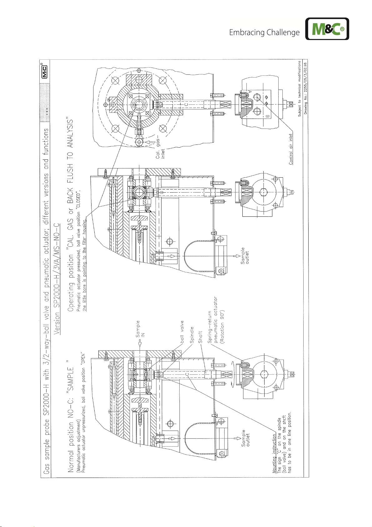
Figure 32 SP2000-H/3VA/MS-NO-C
2-1.1-ME Gas sampling and gas conditioning technology 53
 Loading...