

Page 1
OPERATING INSTRUCTIONS
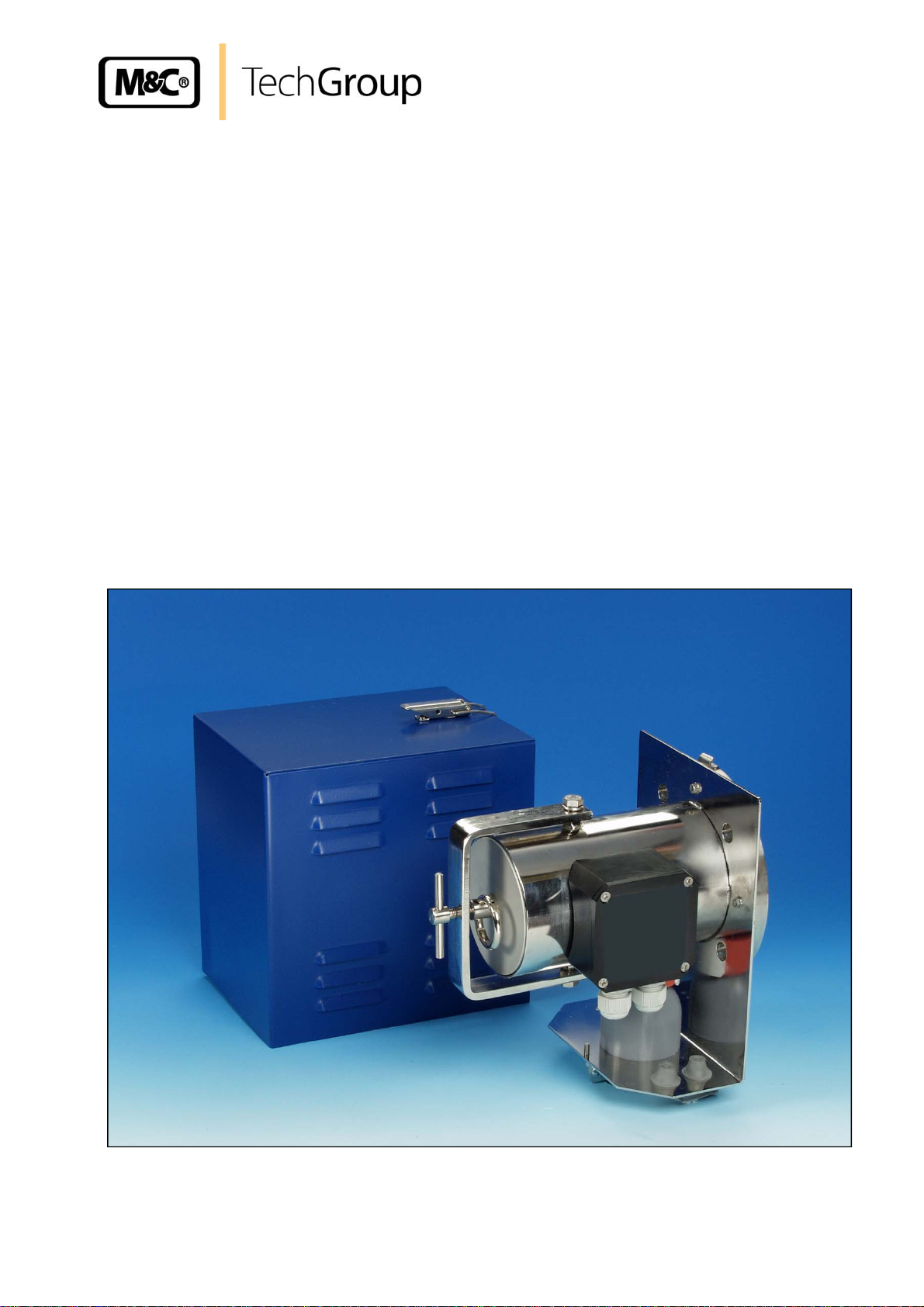
Gas Sample Probe SP®
SP210-H and SP210-H/W
Gas sampling and gas conditioning technology 2-1.0.1-ME
Page 2

2
Dear customer,
we have made up this operating manual in such a way that all necessary information about the
product can be found and understood quickly and easily.
Should you still have any question, please do not hesitate to contact M&C directly or go through your
appointed dealer. Respective contact addresses are to be found in the annexe to this operating
manual.
Please also contact our homepage www.mc-techgroup.com
products. There, you can read or download the data sheets and operating manuals of all M&C
products as well as further information in German, English and French.
for further information about our
This Operating Manual does not claim completeness and may be
subject to technical modifications.
© 08/2000 M&C TechGroup Germany GmbH. Reproduction of this
document or its content is not allowed without permission from M&C.
®
SP
is a registered trade mark.
4th Edition: 08/2005
Gas sampling and gas conditioning technology 2-1.0.1-ME
Page 3

3
Content
1 General information ....................................................................................................................... 4
2 Declaration of conformity ............................................................................................................. 4
3 Safety instructions ........................................................................................................................ 5
4 Warranty ......................................................................................................................................... 5
5 Used terms and signal indications .............................................................................................. 6
6 Introduction .................................................................................................................................... 7
6.1 Serial numbers ......................................................................................................................... 7
6.2 Power supply ............................................................................................................................ 7
7 Technical Data ............................................................................................................................... 8
8 Applications ................................................................................................................................... 8
9 Description ..................................................................................................................................... 9
10 Probe design .................................................................................................................................. 9
11 Reception ..................................................................................................................................... 10
12 Preparation for Installation ......................................................................................................... 10
13 Mounting ....................................................................................................................................... 11
14 Electrical Connection .................................................................................................................. 13
15 Starting Up ................................................................................................................................... 14
16 Maintenance ................................................................................................................................. 14
17 Switching Off ................................................................................................................................ 15
18
Spare parts list ............................................................................................................................. 16
19 Appendix ...................................................................................................................................... 16
List of illustrations
Figure 1 Dimensions SP210-H/W .................................................................................................... 10
Figure 2 Electrical connection diagram ............................................................................................ 13
Figure 3 Replacing the filter element ................................................................................................ 15
Gas sampling and gas conditioning technology 2-1.0.1-ME
Page 4

4
Head Office
M&C TechGroup Germany GmbH Rehhecke 79 40885 Ratingen Germany
Telephone: 02102 / 935 - 0
Fax: 02102 / 935 - 111
E - mail: info@mc-techgroup.com
www.mc-techgroup.com
1 GENERAL INFORMATION
The product described in this operating manual has been examined before delivery and left our works
in perfect condition related to safety regulations. In order to keep this condition and to guarantee a
safe operation, it is important to heed the notes and prescriptions made in this operating manual.
Furthermore, attention must be paid to appropriate transportation, correct storage, as well as
professional installation and maintenance work.
All necessary information a skilled staff will need for appropriate use of this product are given in this
operating manual.
2 DECLARATION OF CONFORMITY
CE - Certification
The product described in this operating manual complies with the following EC directives:
EMV-Instruction
The requirements of the EC directive 2004/108/EC “Electromagnetic compatibility“ are met.
Low Voltage Directive
The requirement of the EC directive 2006/95/EC “Low Voltage Directive“ are met.
The compliance with this EC directive has been examined according to DIN EN 61010.
Declaration of conformity
The EU Declaration of conformity can be downloaded from the M&C homepage or directly requested
from M&C.
Gas sampling and gas conditioning technology 2-1.0.1-ME
Page 5

5
3 SAFETY INSTRUCTIONS
Please take care of the following basic safety procedures when mounting, starting up or
operating this equipment:
Read this operating manual before starting up and use of the equipment. The information and
warnings given in this operating manual must be heeded.
Any work on electrical equipment is only to be carried out by trained specialists as per the regulations
currently in force.
Attention must be paid to the requirements of VDE 0100 (IEC 364) when setting high-power electrical
units with nominal voltages of up to 1000 V, together with the associated standards and stipulations.
Check the details on the type plate to ensure that the equipment is connected to the correct mains
voltage.
Protection against touching dangerously high electrical voltages:
Before opening the equipment, it must be switched off and hold no voltages. This also applies to any
external control circuits that are connected.
The device is only to be used within the permitted range of temperatures and pressures.
Check that the location is weather-protected. It should not be subject to either direct rain or moisture.
The device must not
Installation, maintenance, monitoring and any repairs may only be done by authorized personnel with
respect to the relevant stipulations.
be used in hazardous areas.
4 WARRANTY
If the equipment fails, please contact M&C directly or else go through your M&C authorised dealer.
We offer a one year warranty as of the day of delivery as per our normal terms and conditions of sale,
and assuming technically correct operation of the unit. Consumables are hereby excluded. The terms
of the warranty cover repair at the factory at no cost or the replacement at no cost of the equipment
free ex user location. Reshipments must be send in a sufficient and proper protective packaging.
Gas sampling and gas conditioning technology 2-1.0.1-ME
Page 6

6
5 USED TERMS AND SIGNAL INDICATIONS
This means that death, severe physical injuries and/or important
material damages will occur in case the respective safety measures
DANGER!
are not fulfilled.
This means that death, severe physical injuries and/or important
material damages may occur in case the respective safety
WARNING!
measures are not fulfilled.
This means that minor physical injuries may occur in case the
respective safety measures are not fulfilled.
CARE!
CARE!
Without the warning triangle means that a material damage may
occur in case the respective safety measures are not met.
ATTENTION!
This means that an unintentional situation or an unintentional status
may occur in case the respective note is not respected.
These are important information about the product or parts of the
operating manual which require user’s attention.
NOTE!
SKILLED STAFF
These are persons with necessary qualification who are familiar with
installation, use and maintenance of the product.
Gas sampling and gas conditioning technology 2-1.0.1-ME
Page 7

7
6 INTRODUCTION
M&C gas sample probes provide direct insitu ultra-fine filtration during continuous gas sampling for
analytic measurements. In this way, part of the necessary maintenance work for a system is
concentrated on a single point. This filter technology has the major advantage that dust mixtures
consisting of ultra-fine and coarse dusts can be optimally retained with the least possible maintenance
work.
Optimal adaptation of the sample probe to processing conditions and to measurement work is a
necessary condition for a measurement system to work smoothly. Basically, the gas sample should be
kept to a necessary minimum. This is made possible thanks to optimised downstream gas processing
using M&C components. Only in this way it is possible to reduce maintenance to a minimum while
ensuring maximum availability.
6.1 SERIAL NUMBERS
The nameplates bearing the serial number are located on the side of the electrical connection box.
Always quote the device's serial number when making enquiries and ordering replacement parts.
6.2 POWER SUPPLY
The probe can be operated on alternating current in the range from 110 to 240V.
Gas sampling and gas conditioning technology 2-1.0.1-ME
Page 8

8
3
2
7 TECHNICAL DATA
Gas Sample Probe Series SP® SP210-H SP210-H/W
Part No. 02S1000 02S1010
Weather protection shield no yes
Sample tube Type SP210/SS, stainless steel 316Ti, length 1 m* optional*
Sample temperature max. 600 °C*
Sample pressure 0.4 to 2 bar abs.
Ambient temperature -20 °C to +60 °C
Recommended for dust loadings up to 1 g/m
Filter chamber volume 100 ml
Filter element S-2K, filter porosity 2 μm, ceramic
Probe heating temperature +180 °C self-regulating
Ready for operation after 2 hours
Temperature alarm contact, alarm
point
Temperature alarm, contact rating 250V-3A AC, 30V-3A DC
Connection sample outlet 1/4"-NPT inside, with 6 mm tube connector
Power supply 110 up to 240V 50 / 60Hz
Power consumption start up: 400VA, usual: 100VA, (fuse 6A)
Electrical connection terminals max. 2,5 mm
Electrical equipment standard EN 61010, EN 60335-1
Degree of protection IP54, EN 60529 IP55, EN 60529
Mounting flange DN65 PN6,B stainless steel 316Ti
Material of sample contacting parts SS 316 / 316Ti, FPM, ceramic
Weight 6,5 kg 8,5 kg
Option
Part No.: 02 S 9200 Insitu probe tube out of stainless steel 316Ti type SP210/SS, connection
* Standard, other versions on request.
<160 °C, NO
G3/4" o, ø 10/12, length 1 m*, incl. flange gasket.
*
, 2x PG11 cable gland
ΔP und T90 at flow of:
ΔP pressure loss with new filter element S-2K:
T90 time-without sample tube/prefilter- 6,0 3,5 1,0 Sec.
8 APPLICATIONS
100 200 500 Nl/h
0,007 0,011 0,020 bar
The electrically heated M&C gas sample probes SP210-H and SP210-H/W gas sample probes are
used for continuous gas sampling in processes with dust densities of up to 1g/m³, operating pressure
up to max. 2 bar abs., temperatures of up to a maximum of 600°C or higher gas humidity. Thanks to
its compact design it requires only limited space. It has to be mounted in a weatherproof position. The
gas sample probe SP210-H/W is equipped with an extra protective cover preferably for outdoor
mounting.
Gas sampling and gas conditioning technology 2-1.0.1-ME
Page 9

9
9 DESCRIPTION
The sample probes are designed for easy installation, reliable operation and trouble-free maintenance.
Advantages are:
• Gas sampling with dust loaded processes;
• Low volume, fast response time;
• Filter elements can be changed without tools and without disconnecting the (heated) sample line;
• The filter chamber can be easily cleaned;
• The probe tube can be cleaned without dismantling the probe;
• Self-regulated electrical heating with undertemperature alarm contact;
• Different probe tubes and pre-filters as an option.
The 75 mm ceramic filter element with a filter fineness of 2mm and a large surface is located in the
heated stainless steel filter housing of the probe. The gas sample probe is heated up to +180°C using
a special self-regulated heating element. No thermostat or temperature limiter is necessary. A
separate thermo switch is provided for undertemperature monitoring (< 160°C, NO).
10 PROBE DESIGN
The filter housing with its all-round heating element forms a unit with the standard mounting flange
DN65 PN6 and the laterally mounted junction box.
A mounting clamp and a tube connector are located on the underside of the probe for the connection
of heated M&C sampling lines with external diameters of 40mm to a max. 55mm and a tube diameter
of 6mm. The SP210-H/W is additionally equipped with an integrated silicon cap. A red silicon ring for
the heat insulation of the tube connector is part of the standard delivery.
We are pleased to help you finding a suitable heated M&C sample line for your application.
The gas sample probe outlet connection has a 1/4" NPT internal thread with a screwed in temperature
resistant stainless steel tube connector for a 6mm sample line to connect it in a gas tight manner.
Tube connectors for other sample line dimensions can also be supplied by M&C.
After assembly of the sample line the sample gas outlet connection is enclosed with the red silicon
insulation provided. The mounting clamp and the integrated silicon cap close off the connection to the
exterior.
The stainless steel sampling tube of one meter length (part No.: 02S9200) can optional be provided
and is connected to the G 3/4” thread of the mounting flange. The maximum operating temperature for
stainless steel sampling tube is 600° C. The modular system of our sample probes allows the usage of
all M&C sample tubes and prefilters with G 3/4” connection thread. This guarantees an optimal
adaptation to the process conditions.
Gas sampling and gas conditioning technology 2-1.0.1-ME
Page 10

10
The following cross-sectional drawing shows the probe SP210-H resp. SP210-H/W.
Figure 1 Dimensions SP210-H/W
11 RECEPTION
The gas sample probe is normally delivered in two packaging units:
1. The gas sample probe with the screws, nuts and flange seal required for mounting.
2. Sample tube with gasket.
The gas sample probe should be removed carefully from the packaging and checked immediately for
completeness against the delivery note.
Check the goods for any damage incurred during transport and if necessary inform your transport
insurer of any damage.
12 PREPARATION FOR INSTALLATION
• Select the optimal sampling point in accordance with the generally applicable guidelines or
consult the competent persons.
• Locate the sampling point in such a way that there is adequate space for inserting and
removing the probe and pay attention to the insertion length of the probe tube.
• Make certain that the probe is easily accessible so that you can carry out any subsequent
maintenance work without trouble.
• Locate the probe connections in such a way that the connections' temperature is always above
the acid dew point in order to avoid corrosion and blockage problems. If this is not possible, a
heated SP35/SP30 probe tube is recommended for cold connections.
Gas sampling and gas conditioning technology 2-1.0.1-ME
Page 11

11
• If the ambient temperature in the area of the connections is >80°C as a result of radiated heat,
then a radiated-heat deflector must be mounted to protect the probe.
• The connection's mounting flange connection should comply with DN65 PN6. If other
connection sizes are required, a special adapter flange /S010 can be supplied as an option.
• Before mounting, the probe must be adjusted to the existing operating conditions.
The existing operational parameters are to be checked accordingly prior to commencing mounting
work:
weatherproof mounting position
Under / over pressure situation
Process temperature
Dust loading
Dust composition - grain size
Gas composition
Which parameters should be
measured, e.g. O
, CO, SO2, NOX,..,
2
Required amount of gas
Necessary T90 time
13 MOUNTING
_____present _____set
mbar bar
°C, Min. °C, Max.
g/m³
µm
corrosive toxic explosive
Vol.% mg/Nm³ ppm
l/h, Min. l/h, Max.
sec.
M&C SP210-H probes are designed for stationary use and if properly selected and mounted a long
service life and minimum maintenance are guaranteed. It is advisable to mount the probe in an
operational position which is at a 10% inclination to the process.
Checking the filter element:
• Turn the U-bolt at the front end of the filter receptacle several times to the left until the retaining
bolt can also be turned sideways.
• Remove the filter receptacle at the ring from the probe and check whether the filter element is
screwed on tightly.
• Replace the filter receptacle.
• Place the retaining bolt in its original position and tighten the U-bolt.
Connection of the heated sample line:
• In order to connect the sample line, a threaded tube connector for dimension Ø 6x1mm is
available – other dimensions on request
• Push the silicon cap onto the end of the heated sampling tube
• Introduce the tube connection piece into the bolted pipe joint and connect.
• If a PTFE tube is used as sample line, a carrying bracket must under all circumstances be
inserted in the end of the tube in order to prevent the tube being pressed together.
• The temperature-resistant, stainless steel connectors supplied by M&C have a double-blade
ring system to ensure reliable sealing. After tightening the nuts of these connectors by hand,
they should then be tightened exactly 1¼ of a turn using a flat spanner and are then properly
mounted.
Gas sampling and gas conditioning technology 2-1.0.1-ME
Page 12

12
Make sure that the connection is leakproof !
NOTE!
• Now place the red silicon heat insulation around the connection.
Mounting of sample tube and adapter flange:
• Screw either the probe tube directly into the ¾" inner thread in the flange of the probe with the
¾" flat gasket and tighten.
• If the heated probe tube type SP30/35 is used then the probe is to be screwed to their flange
(with welded threaded bolt). First insert the flange seal between the two flanges.
• If the probe connection does not correspond to the standard flange connection DN65 PN6,
then the optionally supplied adapter flange should be mounted to the probe in the same way.
• Attach the flange seal to the probe connection.
• Now insert the process-internal probe section of the complete probe unit into the probe
connection using the screws and nuts supplied.
NOTE!
A preferred mounting position is to have the probe with its sample gas outlet
pointing downwards, although this is not absolutely necessary for perfect
functioning.
Gas sampling and gas conditioning technology 2-1.0.1-ME
Page 13

a
L
t
j
b
e
e
p
s
c
u
g
A
I
e
n
w
e
n
c
e
n
E
hvolplaAtt010voland
aA m
e
esee
salathe
o
o
n
s
h
e
t
o
e
u
u
o
w
h
r
c
l
e
o
e
e
s
e
n
o
d
m
h
d
h
0
m
c
v
o
b
o
n
t
m
e
s
p
t
w
a
w
m
H
W
e
v
t
a
e
e
o
t
o
i
a
t
a
h
3
w
t
x
r
c
s
i
a
o
o
p
y
V
i
l
g
a
f
e
o
o
m
13
14 E
The junc
unction
Carry out
• R
• R
• In
a
• In
a
• S
• P
ECTRIC
WARN
N
OTE!
ion box is
ox. Two s
the followi
move the
move the
sert the m
propriate t
sert the sig
in the wiri
rew lid ba
t on the w
L CONN
NG!
mounted
parate cab
g steps:
eather pr
lid of the ju
ains cable
rminals a
nal cable t
g below;
k on;
ather prot
W
In
Th
th
It i
CTION
en conne
tage is id
te.
ention m
0) when
tages of
stipulati
ny case
ain switc
main ci
nominal
technica
recomm
rm the fl
probe ar
n the sid
le bushing
tection shi
ction box;
(min. 3 x
in the wiri
rough the
ction shiel
cting the
ntical wit
st be pai
setting
p to 100
ns.
e recom
and mat
cuit must
urrent (o
data.
nded to u
w can be
safe for d
of the pr
are availa
ld at versi
1.5 mm2)
g beside;
ther cable
at versio
equipmen
the infor
to the r
igh-powe
V, togeth
end the u
hing fuse
be equip
er curren
se the lo
stopped
emage.
be. The
le for the
n SP210-
through th
gland and
SP210-H/
, please
ation pro
quiremen
r electric
er with th
e of temp
must be p
ed with a
protecti
tempera
nd the c
iring plan
ains and t
/W;
e cable gl
connect it
;
nsure th
ided on t
s of IEC
l units
associa
rature res
rovided e
fuse cor
n); for ele
ure alarm.
mponent
s located
he signal c
nd and c
o the appr
t the su
e model t
64 (DIN
ith nom
ed standa
istant cab
ternally!
espondin
trical det
In case o
downstr
n the lid
ble.
nnect it t
priate ter
ply
pe
DE
nal
rds
e !
to
ils
an
am
f the
the
inals
Figure 2
Gas s
Electri
mpling and
cal connec
as conditio
ion diagra
ing technol
gy
2-1.0.
1-ME
Page 14
G
o
e
• •
k
c
A
o
b
•••••••
•
g
T
o
a
a
m
a
A
h
a
A
o
t
o
f
o
f
s
e
o
e
c
a
c
e
a
m
h
t
H
n
e
r
n
b
c
e
y
s
s
e
a
e
s
o
r
o
e
e
t
s
a
o
y
)
v
p
o
o
e
n
a
e
o
h
t
e
y
g
e
y
p
o
b
e
c
x
b
o
e
o
o
s
o
p
o
s
s
r
n
e
o
o
,
y
r
r
t
p
o
o
l
e
n
A
e
p
a
s
c
t
14
15
Bef
re starting
stat
d on the p
Switch
The sa
16
The
safety me
wor
!
STAR
1 hour
temper
temper
hours.
MAINT
W
ING UP
up check
robe's nam
n mains p
the probe
ture failur
ture is rea
ple gas c
ENANCE
sures spe
RNING!
whether th
plate.
wer suppl
is already
alarm val
hed.
n now be
ific to the
Prior to
voltage
This al
connect
mains p
. The total
sufficientl
ue (160°C
extracted
plant and
carrying
hould be
o applies
d.
wer suppl
heating-u
heated f
, but it stil
ia the pro
rocess ar
ut mainte
disconne
to any e
voltage c
time is ap
r the tem
l takes ab
e after thi
to be con
nance wo
ted from a
ternal co
rresponds
proximatel
erature to
ut anothe
minimum
ulted prio
k on elec
ll poles!
trol circu
with the i
2 hours.
have exc
hour until
heating-u
to any m
rical part
its which
formation
fter about
eded the
operating
time of 2
intenance
, mains
may be
It is
difficult to
pro
ess conditi
ndication t
n i
am
unt of sam
Pro
e mainten
At versi
Loosen
Pull out
Screw
Check
Check
Check t
Clean
W
f
and
deposit
give any r
ons, a me
at probe-
ple gas in t
nce is res
RNING!
n SP210-
u-bolt c a
the compl
he knurled
ut the filte
ilter eleme
-rings i a
he sealing
ilter cham
.
commend
ningful mai
aintenanc
e analysis
ricted esse
Aggres
Wear pr
High su
Wear pr
/W remov
d swing r
te filter uni
screw g;
’s knurled
t seals h
nd change
in the lid
j
er; It is al
tions as t
ntenance c
may be n
system.
ntially to re
ive conde
tective gl
face temp
tective gl
the weat
taining bol
with lid
d
crew g an
nd replac
if necessar
and chan
so possibl
a particul
ycle must
cessary c
placing filt
sate is p
sses and
ratures!
ves!
er protecti
to the side
and o-ring
d renew filt
if necessa
;
e if necess
to rod th
ar mainten
e elaborat
uld be sh
r elements
ssible.
proper pr
n shield;
;
h and
i
er element
ry;
ary;
rough the
ance cycle
d for the s
wn by a c
and checki
tective cl
the filter e
e
;
probe tub
. Dependin
ecific appl
nstant de
ng seals:
thing!
lement
e
,
in order
g on your
ication.
line in the
the clamp
o remove
as samplin
and gas co
nditioning te
hnology
2-1.0.1-ME
Page 15

15
• O-Ring k is only for guidance of the probe lid and has no sealing function.
The rebuilding has to be done in the reverse order.
Figure 3 Replacing the filter element
17 SWITCHING OFF
Before switching off, i.e. switching off the heating, the probe be flushed with inert gas or air in order to
avoid condensation of aggressive components from the process gas
.
Gas sampling and gas conditioning technology 2-1.0.1-ME
Page 16
16
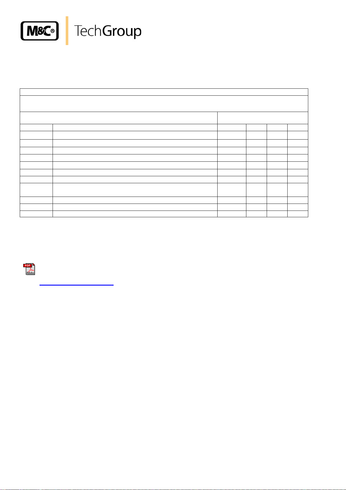
18 SPARE PARTS LIST
Wear, tear and replacement part requirements depend on specific operating conditions.
The recommended quantities are based on experience and they are not binding.
Gas sample probe SP210-H, SP210-H/W
(C) Consumable parts
(R) Recommended spare parts
(S) Spare parts
Part No. Indication
90 S 0015
93 S 0045
93 S 0027
93 S 0029
93 S 0028
90 S 2080
90 S 2077
90 S 2075
93 S 2105
93 S 2110
93 S 2130 Silicon-thermal insulation (red) R 0 1 1
Recommended quantity being in
operation [years]
C/R/S
Ceramic filter element S-2K, 2 µm, 75 mm e
Viton - gasket (30) h
Probe heat sealing plate for SP210-H. Material: Viton. j
Viton O-ring set for SP210-H i
Viton O-ring k
Novapress gasket 3/4" (blue), max. 600°C R 1 2 3
Novapress flange gasket DN65PN6 (67mm i.) R 1 1 1
flange gasket set for DN65 PN6 B, consisting of Novapress
gasket (67mm i.) and screws set M12
Min. temperature contact <160°C R 1 1 1
Cartridge heater HLPSR, 100mm, 110-240V 100W R 2 2 4
C 6 12 18
R 4 8 12
R 2 4 6
R 2 4 8
R 1 2 3
S 1 1 1
1 2 3
19 APPENDIX
Further product documentation can be seen and downloaded from our home page:
www.mc-techgroup.com
• Sample tubes series SP, Document: 2-1.1.0.6
• Prefilter series SP, Document: 2-1.1.0.8
Gas sampling and gas conditioning technology 2-1.0.1-ME
 Loading...