

Page 1

Operating Manual
Gas Sample Probe Series SP ®
Version SP 2000-H320/S, SP2000-H320/S1,
SP2000-H320/S2
Gas sampling and gas conditioning technology 2-1.1.4-ME
Page 2

This Operating Manual does not claim completeness and may be subject to technical modifications.
© 01/2006 M&C TechGroup Germany GmbH. Reproduction of this
document or its content is not allowed without permission from M&C.
SP® is a registered trade mark.
1st Edition: 01/06
2
Dear customer,
we have made up this operating manual in such a way that all necessary information about the product can be found and understood quickly and easily.
Should you still have any question, please do not hesitate to contact M&C directly or go through your
appointed dealer. Respective contact addresses are to be found in the annexe to this operating manual.
Please also contact our homepage www.mc-techgroup.com for further information about our products. There, you can read or download the data sheets and operating manuals of all M&C products as
well as further information in German, English and French.
Gas sampling and gas conditioning technology 2-1.1.4-ME
Page 3

3
Contents
1 General information ............................................................................................................... 5
2 Declaration of conformity ..................................................................................................... 5
3 Safety instructions ................................................................................................................. 6
4 Warranty ................................................................................................................................. 6
5 Used terms and signal indications ....................................................................................... 7
6 Introduction ............................................................................................................................ 8
6.1 Patented probe model ..................................................................................................... 8
6.2 Serial number .................................................................................................................. 8
7 Application ............................................................................................................................. 9
8 Technical data ........................................................................................................................ 9
9 Description ........................................................................................................................... 10
9.1 Construction of the probe .............................................................................................. 10
10 Receipt of goods and storage ............................................................................................ 11
11 Preparation and installation ................................................................................................ 11
12 Mounting ............................................................................................................................... 12
12.1 Dismounting the filter housing cover and checking the filterelement ............................ 13
12.2 Temperature regulator .................................................................................................. 15
12.3 Scope of sampling tubes and prefilters ......................................................................... 15
12.4 Mounting of the probe with extension tube or prefilter .................................................. 16
13 Supply connections ............................................................................................................. 18
13.1 Mounting the sample line .............................................................................................. 18
13.2 Connection of the test gas feeding line ......................................................................... 18
13.3 Connecting the condensate evacuation ........................................................................ 19
13.4 Electrical connection ..................................................................................................... 20
13.4.1 Version SP2000-H320/S with internal capillary tube thermostat .......................... 20
13.4.2 Version SP2000-H320/S1 with electronic temperature controller ........................ 21
13.4.3 Version SP2000-H320/S2 with 2 electronic temperature controllers ................... 22
14 Starting up ............................................................................................................................ 24
14.1 Adjustment of the set value temperature ...................................................................... 25
14.1.1 Version SP2000-H320/S ...................................................................................... 25
14.1.2 Version SP2000-H320/S1 .................................................................................... 25
14.1.3 Version SP2000-H320/S2 .................................................................................... 26
14.2 Test gas feeding ........................................................................................................... 26
14.2.1 Option test gas feeding return valve .................................................................... 26
14.2.2 Option 3/2-Way ball valve /3VA320 ..................................................................... 27
15 Closing down ....................................................................................................................... 27
16 Maintenance and repair ....................................................................................................... 27
16.1 Replacement of the Standard Filter element and control of the seals ......................... 28
16.2 Replacement of the heating cartridge and the thermostat ............................................ 29
17 Spare parts list ..................................................................................................................... 32
18 Connection and mounting data .......................................................................................... 33
19 Annex .................................................................................................................................... 33
Gas sampling and gas conditioning technology 2-1.1.4-ME
Page 4

4
List of Illustrations
Figure 1 Probe construction eg. version SP2000-H320/S1 ............................................................. 11
Figure 2 Mounting possibilities ......................................................................................................... 12
Figure 3 Schematic drawing of the filter housing cover ................................................................... 13
Figure 4 Dismounting of the filter housing lid ................................................................................... 14
Figure 5 Filter element receiving part............................................................................................... 14
Figure 6 Mounting the sample tube or pre-filter ............................................................................... 17
Figure 7 Connection tube on GL adapter ......................................................................................... 18
Figure 8 Connection of test gas line and condensate evacuation ................................................... 19
Figure 9 Electrical connection SP2000-H320/S with thermostat ...................................................... 20
Figure 10 Electrical connection SP2000-H320/S1 with electronic controller eg. type 703G ............. 21
Figure 11 Electrical connection SP2000-H320/S2 with electronic double controller 703G ............... 23
Figure 12 Set value adjustment on Version SP2000-H320/S ............................................................ 25
Figure 13 Schema of test gas (calibration gas) feeding via return valve ........................................... 27
Figure 14 Mounting notice for probes with fibre glass filter element F-0,1GF 150 ............................ 29
Figure 15 Positioning of the thermostat and heating cartridge .......................................................... 30
Figure 16 Positioning of the fixing screws and cable gland ............................................................... 30
Figure 17 Connection box with heating cartridge and thermostat sensor ......................................... 31
Figure 18 Mechanical stop of the thermostat .................................................................................... 31
Figure 19 SP2000-H/Filter elements ................................................................................................. 34
Figure 20 High temperature sample tube max. 1800°C .................................................................... 35
Figure 21 Electrically heated sample tube SP30-H1.1/-H2 ............................................................... 36
Figure 22 SP2000-H320/S ................................................................................................................ 37
Figure 23 SP2000-H320/S1 .............................................................................................................. 38
Figure 24 SP2000-H320/S2 .............................................................................................................. 39
Gas sampling and gas conditioning technology 2-1.1.4-ME
Page 5

5
HEAD OFFICE
M&C TechGroup Germany GmbH Rehhecke 79 40885 Ratingen Germany
Telephone: 02102 / 935 – 0
Fax: 02102 / 935 – 111
E - mail: info@mc-techgroup.com
www.mc-techgroup.com
1 GENERAL INFORMATION
The product described in this operating manual has been examined before delivery and left our works
in perfect condition related to safety regulations. In order to keep this condition and to guarantee a
safe operation, it is important to heed the notes and prescriptions made in this operating manual. Furthermore, attention must be paid to appropriate transportation, correct storage, as well as professional installation and maintenance work.
All necessary information a skilled staff will need for appropriate use of this product are given in this
operating manual.
2 DECLARATION OF CONFORMITY
CE - Certification
The product described in this operating manual complies with the following EC directives:
EMV-Instruction
The requirements of the EC directive 2004/108/EC “Electromagnetic compatibility“ are met.
Low Voltage Directive
The requirement of the EC directive 2006/95/EC “Low Voltage Directive“ are met.
The compliance with this EC directive has been examined according to DIN EN 61010 as well as DIN
57721 for the voltage test of heating elements.
Declaration of conformity
The EU Declaration of conformity can be downloaded from the M&C homepage or directly requested
from M&C.
Gas sampling and gas conditioning technology 2-1.1.4-ME
Page 6

6
3 SAFETY INSTRUCTIONS
Please take care of the following basic safety procedures when mounting, starting up or operating this equipment:
Read this operating manual before starting up and use of the equipment. The information and warnings given in this operating manual must be heeded.
Any work on electrical equipment is only to be carried out by trained specialists as per the regulations
currently in force.
Attention must be paid to the requirements of VDE 0100 (IEC 364) when setting high-power electrical
units with nominal voltages of up to 1000 V, together with the associated standards and stipulations.
Check the details on the type plate to ensure that the equipment is connected to the correct mains
voltage.
Protection against touching dangerously high electrical voltages:
Before opening the equipment, it must be switched off and hold no voltages. This also applies to any
external control circuits that are connected.
The device is only to be used within the permitted range of temperatures and pressures.
Check that the location is weather-protected. It should not be subject to either direct rain or moisture.
The probes SP2000-H320S, SP2000-H320/S1 and SP2000-H320/S2 must not be used in hazardous
areas.
Installation, maintenance, monitoring and any repairs may only be done by authorized personnel with
respect to the relevant stipulations.
4 WARRANTY
If the equipment fails, please contact M&C directly or else go via your appointed M&C dealer.
We offer a one year warranty as of the day of delivery as per our normal terms and conditions of sale
and assuming technically correct operation of the device. Consumables are hereby excluded. The
terms of the warranty cover repair at the factory at no cost or the replacement at no cost of the
equipment free ex user location. Reshipments must be sent in a sufficient and proper protective
packaging.
Gas sampling and gas conditioning technology 2-1.1.4-ME
Page 7

7
DANGER!
This means that death, severe physical injuries and/or important
material damages will occur in case the respective safety measures
are not fulfilled.
WARN ING !
This means that death, severe physical injuries and/or important
material damages may occur in case the respective safety measures are not fulfilled.
CAUTION!
This means that minor physical injuries may occur in case the respective safety measures are not fulfilled.
CAU TIO N!
Without the warning triangle means that a material damage may
occur in case the respective safety measures are not met.
ATT ENT ION
This means that an unintentional situation or an unintentional status
may occur in case the respective note is not respected.
NOTE!
These are important information about the product or parts of the
operating manual which require user’s attention.
SKILLED STAFF
These are persons with necessary qualification who are familiar with
installation, use and maintenance of the product.
5 USED TERMS AND SIGNAL INDICATIONS
Gas sampling and gas conditioning technology 2-1.1.4-ME
Page 8

NOTE!
Please always indicate the serial number of the equipment when you have
questions or in case of ordering spare parts.
8
6 INTRODUCTION
A great problem during extractive and continuous gas analysis are the escort substances of the gas
such as dust, water vapour and also gas components that build up corrosive acids in connection with
condensed water vapour.
It may also occur that solid particles are precipitated when the gas is cooled down. Consequently, the
downstream conditioning device would be choked.
In order to realize a measurement easy to maintain, the dust must be separated and the condensing
of water vapour must be prevented. Thus, you avoid a caking of the dust and the water as well as the
developing of acid. The filter and connected lines will not be choked and the probe material in contact
with the gas will not be attacked by eventual acids. To prevent the subsequent precipitation of solid
particles, they, too, must be separated and removed.
The heated M&C sample probes as for example those of series SP 2000-H.... provide a solution for
this problem. Adequately adapted to the process conditions, these probes guarantee a minimum of
maintenance. During the continuous gas sampling for the analytical measurement, the M&C sample
probes are already filtering the fine dust directly on the sampling point and, if necessary, separate
and remove the solid particles. This way, a great extent of maintenance work on the analysing system is avoided.
Principally, the quantity of the sampled gas should be as low as possible in order to keep the necessary maintenance work to a minimum and to grant a maximum availability. This objective can be
achieved via a subsequent optimized gas conditioning system with components of M&C.
6.1 PATENTED PROBE MODEL
The patented gas sample probe SP2000....., designed in modular construction, is produced by
M&C TechGroup Germany GmbH, D- 40885 Ratingen. [PATENT-NO.: 41 11 377]
6.2 SERIAL NUMBER
The type plates with the serial numbers are to be found where the electrical connection box is placed.
Gas sampling and gas conditioning technology 2-1.1.4-ME
Page 9

9
Gas sample probe Type
SP2000-H320/S
SP2000-H320/S1
SP2000-H320/S2
Part number
20S5000 (a)
20S5005 (a)
20S5010 (a)
Temperature regulation
Thermostat
FeCu-Ni (Regulator optionally)
FeCu-Ni (Regulator optionally)
Probe heating
max. 320 °C
Ambient temperature
+5 °C to +60 °C ** optionally with GFK protective housing -20 °C to +60 °C
Sealing material
Graphite
Material probe flange sealing
Novapress
Sampling tube/Pre filter
Optionally
Sampling pressure max.
0,4 –2 bar* abs.
Volume of filter chamber
120 cm3
Porosity
S – 2K150 = ceramic*, 2 micron, /F-0,1GF150 = Glass fibre** 0,1 micron
/F-3SS150** 3 micron, /FW = Glass fibre-filter cotton**
Ready for work
after 2h
Connection gas outlet
Threaded hose coupling DN 4/6
Connection test gas
Pipe connection Ø 6 mm with blind plug, optionally Ø ¼“ (a)
Power Supply
230V 50/60Hz, 800W, optionally 115V 60Hz (a)
Electrical connection
Terminals max. 2,5 mm2, terminal range 0,75 – 4mm
Standard of electrical equipment
EN 61010, EN 60519-1
Mounting flange
DN 65 PN 6, Form B, 1.4571*, > DN or ANSI possible**
Weight
17 kg
Filter element Type
Filter porosity
Material
S-2K 150
2µm
Ceramic *
S-3SS 150
3µm
Stainl. Steel 1.4401
S-0,1GF 150
0,1µm
Glass fibre
FW
--------
Glass wadding
7 APPLICATION
The probes type SP2000-H320/S.. are used for continuous gas sampling in processes with high dust
load and high temperatures and/or high gas humidity where additionally solid particles may precipitate. M&C has developed these probes for eg. continuous gas sampling in waste gas of DENOX
plants (SCR) where NH3 is added to the flue gas in order to reduce the NOX content. With temperatures of <300 °C, ammonium salts are produced due to the chemical reaction of NH3 and SO2/SO3 in
the flue gas. This salification will choke in a very short time the filters and sample lines.
8 TECHNICAL DATA
* = Standard ** = Option
* = Standard
Gas sampling and gas conditioning technology 2-1.1.4-ME
Page 10

10
9 DESCRIPTION
The probes have been designed for easy mounting, safe operation, easy maintenance and a great
variety of applications.
The main features of this probe are: changing the filter element without tools and without necessity of
dismounting the sample line, easy cleaning of the filter housing, cleaning of the sample tube without
dismounting the probe. The big surface filter element is placed inside a heated filter receiving part of
stainless steel.
The M&C gas sample probe SP2000-H320/S is based on the standard sample probe SP2000-H320.
The temperature regulation of the gas sample probe SP2000-H320/S is made via an integrated capillary sensor thermostat adjustable from 50 to 320 °C including an excess temperature limiter and
alarm in case of insufficient temperature. Optionally, the gas sample probe can be delivered with a
thermocouple FeCu-Ni instead of the thermostat regulator. In this case, an external temperature
regulator is not necessary (eg. 703).
According to the application, it is possible to add sample tubes and pre-filters of different sizes and
versions out of the modular system of M&C probe accessories. All these options are to be mounted
before the probe. In the outlet of the probe, the sample gas is lead via a heated connection adapter
into a non-heated (SP2000-H320/S and SP2000-H320/S1) or into a heated (SP2000-H320/S and
SP2000-H320/S1) collection vessel. Inside the vessel that is made of glass and filled with glass balls
to enlarge the surface, the chemical reaction of the sample gas takes place and the solid particles
and salts are deposited.
On the versions SP2000-H320/S and SP2000-H320/S1 the condensate collected in the collection
vessel is pumped out by the peristaltic pump SR25.1G. The condensate effects that the existing solid
contaminations are withdrawn and transmitted outside. Because of the heated connection adapter
and the hot gas flow, the operating temperature inside the collection vessel is increased compared to
the ambient temperature.
Due to the fact that the gas components are solved to a negligible extent in the warm condensate,
the application of this sampling technique in DENOX systems with a low content of NH3 (normally a
few ppm) allows the analyse of SO2 and NOX without important losses. These will be a few ppm only
and can normally be neglected. In order to examine exactly the extent of the losses, you can feed test
gas on the gas sample probe and determine the eventual measuring fault that can be calibrated afterwards.
On version SP2000-H320/S2 the collecting vessel is equipped with a heater in order to avoid chemical reactions of the sample gas components below a defined temperature as well as to avoid freezing
of the condensate in case the vessel is mounted outside. A heated sample line 3/4-M for max. 200 °C
operating temperature can be connected onto the gas outlet of the collection vessel. The collection
vessel is equipped with a heat isolating protection cover.
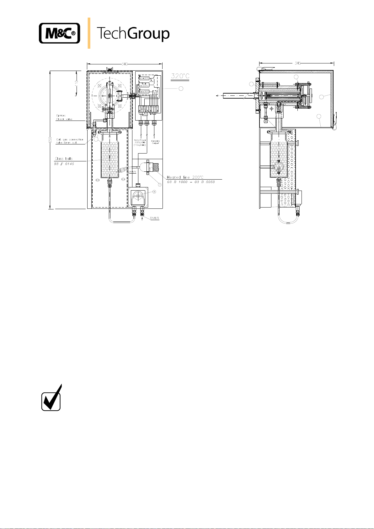
9.1 CONSTRUCTION OF THE PROBE
The complete probe is made up of the heated filter part and a sample tube or pre-filter. The filter receiving part with the surrounding heating jacket is fitted together to a unit with the standard mounting flange DN65 PN6 and the electrical connecting box mounted laterally .
The heat insulated covering cap is placed on the stainless steel angle plate of the mounting
flange and is fixed with 2 fastening clamps. Thanks to the covering cap, the heat is distributed regularly over the probe heating and serves at the same time as weather and contact protection. In the
probe outlet the connection adapter with the collecting vessel is mounted. A mounting clamp is
available for the connection of the heated line. On the probes SP2000-H320/S and SP2000-H320/S1
a peristaltic pump SR25.1 is mounted below the collecting vessel in order to evacuate the condensate.
Gas sampling and gas conditioning technology 2-1.1.4-ME
Page 11
11
1
2
5
4
3
6
NOTE!
The equipment should be stored in a protected, frost-free room!
Figure 1 Probe construction eg. version SP2000-H320/S1
10 RECEIPT OF GOODS AND STORAGE
The gas sample probe and any special accessories should be removed carefully from the packag-
ing and checked immediately for completeness against the delivery note;
Check the goods for any damage incurred during transport and if necessary inform your transport
insurer of any damage.
The gas sample probe is normally delivered in two packaging units:
1. The gas sample probe with the screws, nuts and flange seal required for mounting;
2. Sample tube or pre-filter, if applicable with extension tube.
11 PREPARATION AND INSTALLATION
Select the optimal sampling point in accordance with the generally applicable guidelines of
consult the competent persons.
Gas sampling and gas conditioning technology 2-1.1.4-ME
Page 12

Adapter-
R 2"-threaded
to flange size
Seal according
Mounting fitting
20 S 9005
Seal 3/4"
90 S 2080
90 S 2077
DN65PN6
Seal
20 S 9004
flange
Options Probe Mounting
12
Locate the sampling point in such a way that there is adequate space for inserting and remov-
ing the probe and pay attention to the insertion length of the probe tube! !
Make certain that the probe is easily accessible so that you can carry out any subsequent
maintenance work without trouble.
Make sure that the bleeder connection at site is made up and insulated so that the connec-
tion’s temperature is always above the dew point or above the acid dew point in order to avoid
corrosion and blockage problems as well as washing out effects. If this is not possible, a
heated sample tube SP35 / SP30 is recommended for cold connections.
If the ambient temperature in the area of the connections is >80°C due to radiant heat, then a
rediant heat reflection plate must be mounted to protect the probe.
The mounting flange connection of the connection piece should comply with DN65 PN6. If
other connection sizes are required, a special adapter flange can be supplied as option. Instead of a flange connection mounting, the probe can also be mounted using a R2” adapter
on a corresponding threaded sleeve connection. The required minimum flange size or the
minimum connection piece diameter depends on the outside diameter of the used sample
tube or pre-filter.
Figure 2 Mounting possibilities
12 MOUNTING
The M&C probes SP2000-H320/S.. are designed for stationary use and guarantee a long service life
and a minimum of maintenance provided they are properly selected and mounted. The required position is horizontally.
Gas sampling and gas conditioning technology 2-1.1.4-ME
Page 13

13
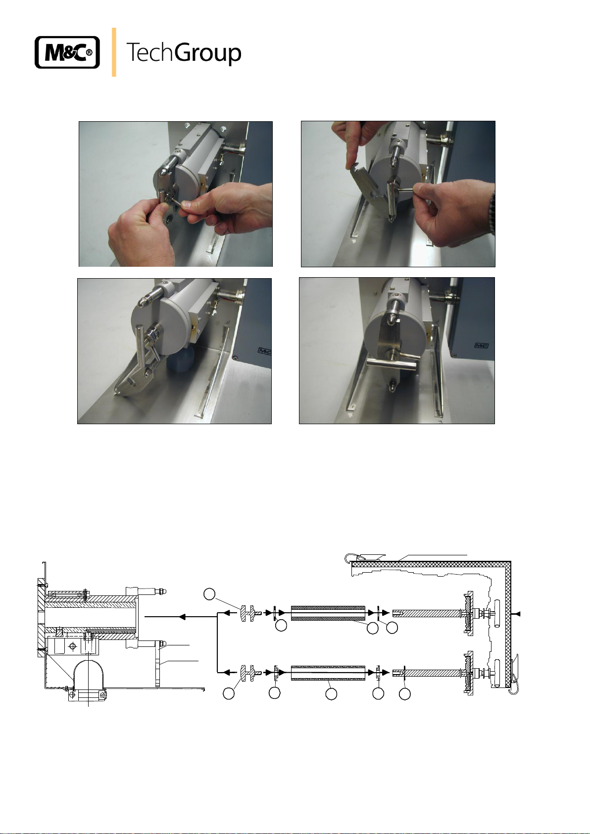
12.1 DISMOUNTING THE FILTER HOUSING COVER AND CHECKING THE FILTERELEMENT
For this purpose, the filter housing cover must be dismounted as follows:
Figure 3 Schematic drawing of the filter housing cover
Remove the protection cover;
Turn the locking handle A for about one rotation to the left so that the lid is moved upwards;
Put the handle C into position E;
Swing the clamp clip B to the left (into direction G);
Pull the filter housing lid out using the locking handle A.
Gas sampling and gas conditioning technology 2-1.1.4-ME
Page 14
Filter screw Seal
Filter screw adapter
Filter space
Holding clip
Strap bolt
93 S 2084
93 S 2084
Schutzhaube wärmeisoliert
90 S 0020
Type S-2K150
Filter element Type F-0,1GF150
90 F 0125
93 S 0053
Filter element
93 S 0055
93 S 0053
Adapter
Seal
93 S 0055
93 S 0055
Seal
I
L
J L K
K I K
J
14
The following photos show how to execute the above mentioned steps.
Figure 4 Dismounting of the filter housing lid
Check on the filter screw I whether the filter element J has been screwed hand-tight (see fig-
ure 20).
Then put in again the filter receiving part, set the handle C into position E, swing the clamp
clip back again and tighten the lid with the locking handle A.
Figure 5 Filter element receiving part
Gas sampling and gas conditioning technology 2-1.1.4-ME
Page 15
15
Selection of materials
Type
Max. process
temperature
Max. length
Outside tube diameter
(sleeve or adapter)
Stainl. Steel 1.4571
SS
600 °C
2,5 m *
25 (37)mm
Titanium
Ti
400 °C
2,5 m *
25 (37)mm
Hastelloy
HC
900 °C
2,5 m *
25 (37)mm
Inconel
IN
1100 °C
2,0 m *
25 (37)mm
Chrome-Aluminium
oxide
CR
1400°C
1,2m
23 (37)mm
Kanthal
Ka
1300 °C
2,5 m *
25 (37)mm
Aluminium-Oxide
AO
1800 °C
1,5 m *
25 (55)mm
PVDF
PV
90 °C
1,5 m *
25 (37)mm
PTFE
T
160 °C
0,5 m
33mm
Incoloy
IC
1200 °C
2,0 m *
25 (37)mm
Type
Max.
Process temperature
Max. length
Outside diameter of the
tube
SP32
90 °C
0,8 m *
50mm
Type
Max. Process
temperature
Max.
length
Outside tube diameter
SP30-H1.1, heating max. 320°C
550 °C
2,0 m *
42,4mm
SP30-H1.1V, heating max. 320°C
550 °C
1 m
42,4mm
SP30-H2, heating max. 320°C
350 °C
2,0 m *
42,4mm
SP35H.1, heating max. 320°C
550 °C
0,175 m
42,4mm
SP35H.2, heating max. 320°C
350 °C
0,175 m
42,4mm
12.2 TEMPERATURE REGULATOR
On version SP2000–H320/S the temperature regulation is effected by the capillary thermostat
mounted inside the connecting box. The range of regulation is from 50 to 320°C.
On the versions SP2000-H320/S1 and SP2000-H320/S2 the regulation is made by means of an external electronic regulator. M&C supplies appropriate temperature regulators, eg. Type 703G (see
data sheet 2-5.1) or Type 703G double that can be mounted separately or directly on the gas sample
probe (max. ambient temperature +45°C).
12.3 SCOPE OF SAMPLING TUBES AND PREFILTERS
Depending on the process gas temperature and composition, sample tubes of different materials with
connector G ¾” are applicable:
*Standard = 1m
Further information on sampling tubes see data sheet 2-1.1.0.6
In case gas has to be sampled behind wet washers, the Demister sampling tube of PVDF with connector G ¾” has to be applied in order to evacuate the droplets:
*Standard
In order to avoid condensation between the sampling point and the heated gas sample probe or con-
densation in the area of the connection piece, heated sample tubes have to be applied made of
stainl. Steel with flange connection DN65 PN6.
*Standard = 1m
Gas sampling and gas conditioning technology 2-1.1.4-ME
Page 16

Dust load
Type
Max. Process
temperature
Outside diameter of the pre-
filter (with keep-off plate)
< 2 g/m³
without, only sample tube
see above
see above
2-10 g/m³
/V20, /V20-0,
600°C
50mm (60mm)
/V20-3, /V20-4,
600°C
31mm [sleeve 37mm]
/V20/HC, /V20-0/HC,
900°C
50mm (60mm)
> 10 g/m³
/V20-1, /V20-2
600°C
60mm (65mm)
/V20-1/HC, /V20-2/HC
900°C
60mm (65mm)
/V12-1,/V12-2,/V12-3
1000°C
60mm, /V12-1 = 40mm
/V12-1/SS,/V12-2/SS,
/V12-3/SS
600°C
60mm, /V12-1/SS = 40mm
/V12-1/IC,/V12-2/IC,
/V12-3/IC
1000°C
60mm, /V12-1/IC = 40mm
/V20-T
200°C
40mm
16
If there is a high dust load in the process gas, we urgently recommend the use of a pre-filter in order
to increase the service life. They can be supplied with a volume displacement to shorten the response
time. The pre-filters can be directly screwed into the probe flange or on request with extension tubes
equipped with a volume displacer.
Further information on the pre-filters see data sheet 2-1.1.0.8.
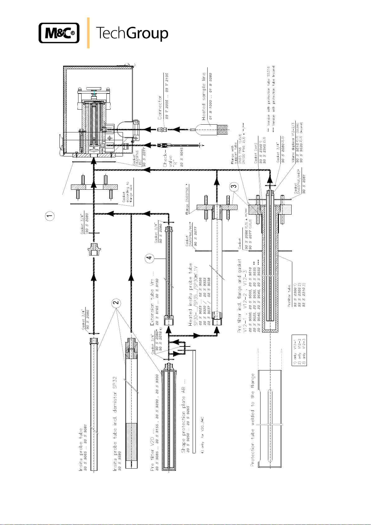
12.4 MOUNTING OF THE PROBE WITH EXTENSION TUBE OR PREFILTER
The installation position is horizontally. When using the sample tube type SP32 eg. for sampling behind wet washers, it is absolutely required to mount the probe with a gradient of 10° so that the separated droplets can flow back into the process!
Put the flange seal between the sample flange and the probe flange.
In case the heated sample tube type SP30/35 or the ceramic pre-filter type V12.. are used,
you must screw first the probe with its flange (with threaded bolt welded inside). Here too,
the flange seal has to be put between both flanges.
If the flange on the bleeder connection does not correspond to the standard flange connection
DN65 PN6, please use the optionally delivered adapter flange (figure 2) and mount it the
same way to the probe.
The sample tube or the pre-filter with thread G¾“a are to be screwed into the G3/4” inside
thread in the flange of the probe either directly or together with an extension tube and the
flat seal 3/4" and tighten.
Introduce the process internal sampling part of the complete probe unit into the bleeder con-
nection (pipe) and screw the probe onto the bleeder connection (pipe) by using the screws
and nuts attached to the packing.
Gas sampling and gas conditioning technology 2-1.1.4-ME
Page 17
17
Sealing
DN65 PN6
90S2077
Figure 6 Mounting the sample tube or pre-filter
Gas sampling and gas conditioning technology 2-1.1.4-ME
Page 18

NOTE!
For probe type SP2000-H320/S.. it is important to use a heated line with ex-
changeable PTFE core only.
18
13 SUPPLY CONNECTIONS
13.1 MOUNTING THE SAMPLE LINE
Open the fastening clip of the sample line.
Unscrew the union nut of the connecting adapter GL18-DN4/6 and put it together with the
clamping ring in the correct order and direction over the 6mm PTFE core of the heated
line.
Put the PTFE core on the connection piece inside the connection adapter and fasten the
union nut with clamping ring hand-tight.
Shut the fastening clip of the sample line.
Figure 7 Connection tube on GL adapter
13.2 CONNECTION OF THE TEST GAS FEEDING LINE
When using the standard execution or execution with a 3-way ball valve option /3VA320 in the probe
inlet for test gas feeding, an appropriate pipeline has to be connected to the 6mm pipe socket be-
low the probe housing by means of the attached tube connector. During the measurement, this tube
connector has to be closed with the attached blind cap.
Optionally, a check valve can be mounted in the test gas inlet for thermal decoupling. Also in this
case, an appropriate pipeline has to be connected to the 6mm pipe socket below the probe housing
and by means of the respective tube connector.
Gas sampling and gas conditioning technology 2-1.1.4-ME
Page 19

19
1
2
Calibration gas connection
6mm tube
WA RNI NG !
Aggressive condensate possible.
Wear safety glasses and Appropriate protective clothes!
Figure 8 Connection of test gas line and condensate evacuation
13.3 CONNECTING THE CONDENSATE EVACUATION
On versions SP2000-H320/S and SP2000-H320/S1 the condensate is evacuated via a peristaltic
pump SR25.1.
In order to carry away the condensate, a tube with 6mm outside diameter has to be connected to the
condensate outlet DN4/6 .
On version SP2000-H320/S2 no peristaltic pump is integrated because no condensate is arising.
Gas sampling and gas conditioning technology 2-1.1.4-ME
Page 20

WA RNI NG !
Wrong supply voltage can destroy the equipment. when connecting the device, please ensure that the supply voltage is identical with the information provided on the type plate!
WA RNI NG !
Attention must be paid to the requirements of IEC 364 (DIN VDE
0100) when setting high-power electrical units with nominal voltages of up to 1000V, together with the associated standards and
stipulations!
A main switch must be provided externally.
The main circuit must be equipped with a fuse corresponding to
the nominal current (over current protection); for electrical de-
tails see technical data.
20
13.4 ELECTRICAL CONNECTION
13.4.1 VERSION SP2000-H320/S WITH INTERNAL CAPILLARY TUBE THERMOSTAT
Remove the lid of the connection box. Inside the lid, you can see the terminal connecting plan.
Insert the mains cable (min. 3 x 1,5 mm2, terminal range 6-12mm) through the left cable gland
and connect it to the appropriate terminals.
Insert the signal cable (terminal range 6-12mm) through the right cable gland and connect it to
the appropriate terminals.
Screw lid on again.
Figure 9 Electrical connection SP2000-H320/S with thermostat
Gas sampling and gas conditioning technology 2-1.1.4-ME
Page 21

21
NOTE!
As sensor line an equalization line has to be provided. The corresponding thermo equalization terminals are provided inside
the connection box.
13.4.2 VERSION SP2000-H320/S1 WITH ELECTRONIC TEMPERATURE CONTROLLER
The gas sample probe is supplied either as unit with a fixed and electrically connected temperature
controller, or the temperature controller is attached as separate unit for external mounting. Then, the
electrical connection is to be made as follows:
Remove the lid of the connection box on the gas sample probe. Inside the lid, you will find the
terminal connection plan.
Insert the mains cable (min. 3 x 1,5 mm2, terminal range 6 – 12mm) through the medium cable
gland of the gas sample probe and connect it to the appropriate terminals.
Insert the temperature sensor cable into the right cable gland of the gas sample probe and
connect it to the appropriate terminals.
Screw the lid on again.
Figure 10 Electrical connection SP2000-H320/S1 with electronic controller eg. type 703G
Gas sampling and gas conditioning technology 2-1.1.4-ME
Page 22

CAU TIO N!
In case you should not use all cable glands when connecting the temperature controller, it is important to shut the cable glands in order to provide
the tightness of the housing.
The electrical connection of the temperature controller Type 703G is to be made according to the
terminal connecting plan as shown in figure 10 and described as follows:
Unscrew the housing lid.
Insert the mains cable (min. 3 x 1,5 mm2, terminal range 6 – 12mm) into the left cable gland of
the controller and connect it to the appropriate terminals.
Insert the cable for the alarm contact (terminal range 6 – 12mm) into the right cable gland and
connect it to the appropriate terminals.
In case the temperature controller Type 703G is delivered as separate unit, then the probe has additionally to be connected with the controller according to figure 13 and as described as follows:
Insert the power supply cable for the gas sample probe (min. 3 x 1,5 mm2, terminal range 6 –
12mm) through the second cable gland of the controller and connect it to the appropriate terminals.
Insert the temperature sensor cable (terminal range 6 – 12mm) through the third cable gland
of the controller and connect it to the appropriate terminals.
Screw the housing lid on again.
22
13.4.3 VERSION SP2000-H320/S2 WITH 2 ELECTRONIC TEMPERATURE CONTROLLERS
The gas sample probe is supplied either as unit with a fixed and electrically connected temperature
controller, or the temperature controller is attached as separate unit for external mounting. Then, the
electrical connection is to be made as follows:
Remove the lid of the connection box on the gas sample probe. Inside the lid, you will find the
terminal connection plan.
Insert the mains cable (min. 3 x 1,5 mm2, terminal range 6 – 12mm) through the medium cable
gland of the gas sample probe and connect it to the appropriate terminals.
Insert the temperature sensor cable into the right cable gland of the gas sample probe and
connect it to the appropriate terminals.
Screw the lid on again.
Gas sampling and gas conditioning technology 2-1.1.4-ME
Page 23

23
NOTE!
As sensor line an equalization line has to be provided. The appropriate
thermo equalization terminals are available inside the connection box.
Figure 11 Electrical connection SP2000-H320/S2 with electronic double controller 703G
The electrical connection of the temperature controller Type 703G is to be made according the terminal connection plan as shown in figure 11 and being described as follows:
Screw off the housing lid.
Insert the mains cable (min. 3 x 1,5 mm2, terminal range 6 – 12mm) through the left cable
gland and connect it to the appropriate terminals.
Insert the cable for the alarm contact (terminal range 6 – 12mm) through the fifth cable gland
and connect it to the appropriate terminals.
In case the temperature controller Type 703G is delivered as separate unit, the probe is to be connected according to figure 11 and as described as follows:
Insert the mains cable for the gas sample probe (min. 3 x 1,5 mm2, terminal range 6 – 12mm)
through the second cable gland of the controller and connect it to the appropriate terminals.
Insert the temperature sensor cable (terminal range 6 – 12mm) through the third cable gland
of the controller and connect it to the appropriate terminals.
Screw the housing lid on again.
Gas sampling and gas conditioning technology 2-1.1.4-ME
Page 24

CAU TIO N!
In case you should not have used all cable glands when connecting the temperature controller, it is important to shut the cable
glands in order to provide the tightness of the housing.
NOTE!
In case the set value indication on the thermostat is adjusted during operation in one step for more than 28°C downwards, this ac-
tivates the thermostat’s excess temperature switch off! For
switching on again, the reset button must be actuated.
WARN ING !
For works during operation:
High surface temperatures!
Any contact may cause burnings.
Wear protective gloves and protect the probe against unauthor-
ized access!
24
14 STARTING UP
Before starting up, check whether the supply voltage corresponds to the indication on the type
plate.
Control whether the eventually integrated ball valve is connected. The turning handle of the
hand operated ball valve must be in position on the right limit stop.
Switch on the power supply.
Control the set value on the integrated thermostat or on the external regulator. (see 14.1).
The total heating time is approx. 2 h. After approx. 1 h the probe is heated up so far that the
temperature has exceeded the below temperature alarm (30°C below set value).
If there is a ball valve present, turn it with the turning handle until the left limit stop in case of a
2/2-way ball valve or until the medium position in case of a 3/2-way ball valve.
Now, the probe is ready for work.
Gas sampling and gas conditioning technology 2-1.1.4-ME
Page 25

25
CAU TIO N!
The maximum temperature of the device to be controlled must be heeded
because otherwise the equipment may be damaged or destroyed.
Adjustment knob
14.1 ADJUSTMENT OF THE SET VALUE TEMPERATURE
If the sample probes are delivered together with the temperature controllers 703 or double 703, then
the temperature controllers are parameterized for the sample probe. The adjusted set value of the
temperature is 320°C for the sample probe and 180°C for the heated separator.
In case there must be changed another parameter than the set value temperature, you can read how
to proceed in the separate operating manual of the temperature controller 703 (2-5.1.1MD).
14.1.1 VERSION SP2000-H320/S
Open the lid of the connection box.
The adjustment of the set value is made via the control knob of the thermostat to be found
inside the connection box. The value can be adjusted between 50°C and max. 320°C.
The thermostat has got an excess temperature limiter that switches off automatically and per-
manently the heating in case the set value temperature is exceeded by 30°C. For switching
the heating on again, the RESET-button has to be actuated which is situated below the opening in the mounting plate of the thermostat.
Figure 12 Set value adjustment on Version SP2000-H320/S
14.1.2 VERSION SP2000-H320/S1
The following steps have to be effected on the controller 703:
Push the PGM-key for a short time. On the display you can read “SP1”.
Adjust the desired set value by using the arrow keys in the above display.
Wait until the set value is flashing for a short time, then it is fixed.
Push the PGM-key twice for return to the normal reading.
Gas sampling and gas conditioning technology 2-1.1.4-ME
Page 26

NOTE!
Pay attention – in case of low pressure operation – that it may occur that
secondary air is sucked via the non-shut return valve if there is less than
300 mbar abs.
26
14.1.3 VERSION SP2000-H320/S2
The following steps have to be effected on the controller 703:
Adjustment of the set value on the sample probe:
Push the PGM-key for a short time. You can read “SP1” on the below display.
Adjust the desired set value by using the arrow keys in the above display.
Wait until the set value is flashing for a short time, then it is fixed.
Push the PGM-key twice to return to the normal reading.
Adjustment of the set value of the heated separator:
The actual set value SP1 can be changed directly on the standard reading via the arrow keys .
After the changing, the new value is flashing for short time and is fixed then.
14.2 TEST GAS FEEDING
During the test gas (calibration gas) feeding, the analyse system remains connected.
The test gas quantity should be at least 25 % higher than the sucked sample gas quantity in
order to avoid a mixing with the sample gas.
If you have processes with excess pressure or low pressure, we recommend an integrated ball
valve in the probe inlet. In this case, a small quantity of test gas is sufficient because the
probe is separated from the process by actuating the ball valve. For shutting the hand actuated ball valve, turn the turning handle to the right until the limit stop.
14.2.1 OPTION TEST GAS FEEDING RETURN VALVE
When feeding test gas via the return valve (check valve) of the probe, a mixing with the sample gas
must be avoided. The flow rate of the test gas should be at least 25 % higher than the sample gas
quantity.
Gas sampling and gas conditioning technology 2-1.1.4-ME
Page 27

27
Figure 13 Schema of test gas (calibration gas) feeding via return valve
14.2.2 OPTION 3/2-WAY BALL VALVE /3VA320
When feeding the test gas, the probe is automatically separated from the process and, therefore, only
a small quantity of test gas is necessary as no mixing with the sample gas may occur.
For the measurement operation, set the ball valve into the central position.
For the test gas feeding, turn the ball valve to the right until the limit stop.
For the measurement operation, set the ball valve into the central position again.
15 CLOSING DOWN
Before closing down, i.e. switching off the heating, the probe should be purged with inert gas or air to
avoid condensation and an eventual acidification.
16 MAINTENANCE AND REPAIR
Prior to any maintenance work, the safety instructions specific to the plant and the process have to be
observed!
It is difficult to give any recommendation as to a particular maintenance cycle. Depending on your
process conditions, a meaningful maintenance cycle has to be found for your specific application.
An indication that a probe maintenance may be necessary can be shown by a constant decrease of
the sample gas quantity in your analyse system.
Probe maintenance is essentially to be concentrated on the replacement of the filter elements and
control of the seals.
Gas sampling and gas conditioning technology 2-1.1.4-ME
Page 28

WARN ING !
Aggressive condensate possible.
Wear protective glasses and protective clothes!
WARN ING !
For works during operation:
High surface temperatures!
Any contact may lead to burnings.
Wear protective gloves and protect the probe against unauthor-
ized access!
28
16.1 REPLACEMENT OF THE STANDARD FILTER ELEMENT AND CONTROL OF THE
SEALS
Shut the ball valve (if present). Purge the probe if toxic gases have been used!
Remove the protective cover.
Take out the filter receiving part as described in chapter 12.1.
Unscrew the filter knurled screw I and replace the filter element J.
Control the filter element seals K and replace them if necessary.
Control the flat seal of graphite inside the lid and replace it if necessary.
Clean the filter space.
Push eventually through the sample tube to remove any deposits.
Caution! Risk of fracture when using sample tubes of aluminium oxide.
Then insert the filter receiving part again. Set the handle C in position E and tighten the lid
again by using the locking handle A.
Put on the protective cover.
Open the ball valve.
Gas sampling and gas conditioning technology 2-1.1.4-ME
Page 29

29
Mounting notice
Screw in knurled screw “1” until the filter
element is tightend slightly.
Afterwards screw in the knurled screw “1”
an additional rotation (360°)
1 Filter screw 93S2084
2 Gasket (30) 93S0055
3 Filter element 0,1 µm 90F0125
4 Adaptor ring stainl. Steel 93S0053
5 Gasket (69) 93S0030
6 Fixing disk 93S0034
7 Filter housing lid 93S2086
NOTE!
For replacement of the pre-filters, remove the complete probe
unit out of the process. The pre-filters can be cleaned mechanically or in the ultrasonic bath according to the degree of contamination and be used again.
WA RNI NG!
Prior to works on any electrical parts, the power supply has to
be switched off on all poles! this is also valid for all eventually
connected alarm or control circuits.
Gas sample probe SP2000-H320/0,1GF with 0,1µ fibre glass filter element
Figure 14 Mounting notice for probes with fibre glass filter element F-0,1GF 150
16.2 REPLACEMENT OF THE HEATING CARTRIDGE AND THE THERMOSTAT
Switch the probe free from voltage (Switch off the power supply) and let the probe cool down.
Remove the weather protection cover.
Gas sampling and gas conditioning technology 2-1.1.4-ME
Page 30

Heating cartridge
Thermostat
Hexagon head screws “B“
Cable gland “C“
Hexagon head screws “A“
30
Figure 15 Positioning of the thermostat and heating cartridge
Remove the lid of the electrical connection box after having loosened the 4 screws.
Unscrew both screws “A“ on the bottom of the connection box (figure 16) which are serving to
mount the connection box on to the holding clip.
Unscrew the hexagon head cap screws “B“ (figure 16) which are serving to fix the heating car-
tridge receiving plate and the thermostat sensor receiving plate.
Figure 16 Positioning of the fixing screws and cable gland
Remove the connection box including heating cartridge and thermostat sensor (figure 17)
Loosen the leading-in cable gland “C“ for the heating cartridge and the capillaries of the ther-
mostat.
Gas sampling and gas conditioning technology 2-1.1.4-ME
Page 31

31
Mechanical Stop
Fixing Screws
Turning knob
Figure 17 Connection box with heating cartridge and thermostat sensor
Disconnect on the terminal strip the electrical connection lines of the heating cartridge and of
the thermostat.
Tear off the turning knob on the thermostat. Remove both fixing screws being under there (see
figure 18). Remove also the 2 fixing screws of the thermostat receiving plate.
Tear out the heating cartridge through the cable gland “C“.
Tear out the thermostat sensor of the aluminium block and through the cable gland in the op-
posed direction.
Mount the new thermostat and lead the thermostat sensor through the cable gland.
Also lead in the new heating cartridge through the cable gland.
Connect the electrical lines according to terminal connecting plan.
Mount the complete unit on to the probe again.
The thermostat has got a mechanical stop that is limiting the maximum adjustable temperature to be
set by using the turning knob.
When mounting the thermostat, this mechanical stop must be adjusted in such a way that the arrow
on the metal ring shows the desired maximum temperature (standard adjustment 190°C).
Figure 18 Mechanical stop of the thermostat
If you use gas sample probes with temperature sensor (PT100 or thermo element) instead of the
thermostat, you must lead the sensor connection line together with the heating cartridge through the
cable gland. For this purpose, put the connection line into the bead of the sealing ring the two metal
rings.
Gas sampling and gas conditioning technology 2-1.1.4-ME
Page 32

Gas sample probe SP2000...
(V) Consumable parts and (E) recommended spare parts
Recommended quantity
being in operation for [years]
Part No.
Description
V/E 1 2
3
90 S 0020
Filter element Type S-2K150. Length 150mm,
Material ceramic, Filter porosity: 2µm
V 5 10
15
90 F 0125
Filter element Type F-0,1GF150. Length
150mm, Material glass fibre, Filter porosity:
0,1µm
V 5 10
15
93 S 2096
Filter glass wool for probe SP2..00../FW
analytical clean and heat resistant up to
690°C, Packing of 1kg
V 2 4
6
93 S 0053
Spare receiving adaptor stainl.steel / sealing
ring (30) for filter element F-0,1GF150
E 2 4
6
93 S 0055
Spare gasket (30) for filter element SP2000H
320/S-2K150
E
10
20
30
93 S 0030
Spare gasket of graphite (69) for filter housing
lid SP2000/H320
E 2 4
6
93 S 0011
Thermostat 0 to 320°C, with excess
temperature limiter and low temperature alarm
30°C to T set value, Sensor diameter 8mm
E 1 1
1
93 S 0015
Heating cartridge for SP2000-H, L=160mm,
230VAC/800W
E 1 1
1
93 S 0017
Heating cartridge for SP2000-H, L=160mm,
115VAC/800W
E 1 1
1
93 F 0130
Spare glass for electrically heated separator
Type SDH flange execution exit laterally on
the bottom
E 1 1
1
01 P 1000
Peristaltic pump SR25.1, 115/230V
E
1
90 P 1007
Spare flexible tube set for peristaltic pump
SR25 with PVDF connector unions DN 4/6mm
V 2 4
6
32
17 SPARE PARTS LIST
Gas sampling and gas conditioning technology 2-1.1.4-ME
Page 33

33
Gas sample probe Type
SP2000-H320/S
SP2000-H320/S1
SP2000-H320/S2
Dimensions B x H x T
340 x 650 x 345
Material filter housing
Stainl. Steel 1.4571*
Sealing material
Graphite
Material probe flange seal
Novapress
Low temperature alarm contact
Capacity: 250V,3A~, 0,25A=,
Switching point: T 30 °C
See 703
See 703
Connection gas outlet
DN4/6
Connection test gas
Pipe Ø 6 mm
Voltage supply /Capacity /Fuses
230V 50/60Hz, 800W, /115V** = 115V 60Hz, 800W
Fuse 10A
Electrical connection
Terminals max. 4 mm2, 2 x M20 x 1,5 cable gland
Mounting flange
DN 65 PN 6, Form B, 1.4571*, > DN or ANSI possible**
Controller Type
703G
703 2-fach
Dimensions B x H x T
150 x 250 x 145
260 x 280 x 140
Status signal output
Low temperature alarm: 1 contact NO, potential
free.
Capacity max. 250VAC 3A
Low temperature alarm: 2 contacts NO,
potential free.
Capacity max. 250VAC 3A
Electrical connection
Terminals max. 4 mm2, 4 x M20 x 1,5 cable gland
Additional energy
115V 50/60Hz 1725VA, 230V 50/60Hz 3450 VA
18 CONNECTION AND MOUNTING DATA
* = Standard ** = Option
19 ANNEX
SP2000-H/Filter elements drawing No.: 22551050
High temperature sample tube max. 1800°C drawing No.: 22551040
Electrically heated sample tube SP30-H1.1/-H2 drawing No.: 22091024
SP2000-H320/S, drawing No.: 22551137
SP2000-H320/S1, drawing No.: 225511301
SP2000-H320/S2, drawing No.: 225511303
Further product documentation is available on our internet catalogue:
www.mc-techgroup.com
Gas sampling and gas conditioning technology 2-1.1.4-ME
Page 34

34
Figure 19 SP2000-H/Filter elements
Gas sampling and gas conditioning technology 2-1.1.4-ME
Page 35

35
Figure 20 High temperature sample tube max. 1800°C
Gas sampling and gas conditioning technology 2-1.1.4-ME
Page 36

36
Figure 21 Electrically heated sample tube SP30-H1.1/-H2
Gas sampling and gas conditioning technology 2-1.1.4-ME
Page 37

37
Figure 22 SP2000-H320/S
Gas sampling and gas conditioning technology 2-1.1.4-ME
Page 38

38
Figure 23 SP2000-H320/S1
Gas sampling and gas conditioning technology 2-1.1.4-ME
Page 39

39
Figure 24 SP2000-H320/S2
Gas sampling and gas conditioning technology 2-1.1.4-ME
 Loading...