

Page 1
SP2000-H/DIL
Embracing Challenge
Gas Sample Probe Series SP®
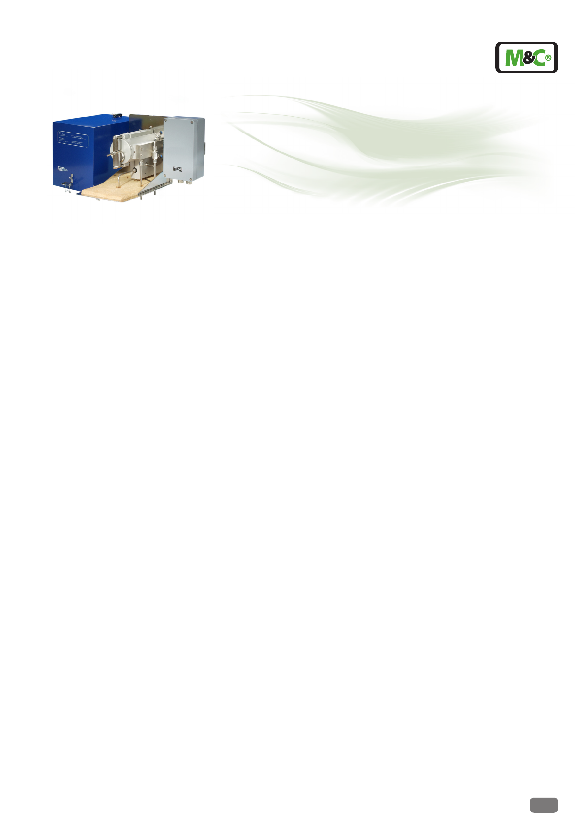
Version SP2000H/DIL... and SP2000H320/DIL...
Gas Sample Dilution Probe
Special Features
Based on probe SP2000H/....
Electrically heated up to 180 °C or 320 °C
External critical orice is heated
Including a dilution gas pre heater
No dew point problems
Dilution ratios from 10:1 up to 500:1
With check gas connection
Independent of the process temperature
Easy operation and maintenance
Application
The non-heated or electrically heated M&C
dilution unit DIL-1/H is used in analysis technique to dilute the sample gas or components in the sample for example in case of
toxic gases, moisture measurement or emission measurement.
The M&C dilution unit is based on the functional dilution technique which is proved
since years in the M&C gas sample probe
SP2000-H/DIL.
Description
The M&C dilution units DIL-... are mounted on
a plate for wall mounting. The version DIL-1 is
not heated and works at ambient temperature. The version DIL-1/H is electrically heated
up to 180°C . It is additionally equipped with
a lagged cover (version for 320°C on request).
A capillary thermostat controlls the
temperature, adjustable from 0-180°C.
A high temperature limiter and a low temperature alarm is included.
The connection of the heated lines is
made without cold bridges in the heated
part. Before the dilution gas enters the
dilution unit, it is heated up to operating temperature via a gas pre-heater. In
order to protect the dilution part against
contaminations, internal protective filters are installed for the sample gas and
the dilution gas stream. Calibration gas can be
feeded via the integrated connection.
A precision pressure controller with pressure
gauge is used for adjustment of the necessary
admission pressure of the dilution gas. Via a
vacuum pressure gauge, the function of the
dilution injector is controlled.
Both, pressure controller and pressure gauges
have to be ordered separately. Two versions
are available: Set -A (-A1) is mounted directly
on the mounting plate and control panel type
-S (-S1) is suitable for external 19» rack mounting. A shut off valve and a flowmeter for
adjustment of the calibration gas are included
in the version -S (-S1).
The dilution unit can realize dilution ratios
of 10:1 to 500:1. In case of high dilution
ratios, a respective small quantity of gas
is sampled from the process. Optionally
a bypass injector -B (Option I) is available
integrated right in front of the dilution unit
in order to shorten the response time in case
of operation with atmospheric pressure or
low pressure. In case of option I, an additional
pressure controller is included in both mounting versions.
The construction of the dilution unit guarantees easy maintenance and operation independent from process temperatures.
Technical specications and illustrations are without
obligation, subject to modications. 08.99/06.06
M&C TechGroup Germany GmbH • Rehhecke 79 • 40885 Ratingen • Germany
info@mc-techgroup.com • www.mc-techgroup.com • Fon +49 2102 935-0 • Fax +49 2102 935-111
5.1
Page 2
132 (3HE)
19" (84TE)
SP2000H/DIL...
-S1
-S
-S
-0,2
0,0
-0,8
-1,0
-0,6
-0,4
Open
Test gasInjector-Underpressure
Open
Dilution gas
5,0
6,0
4,0
0,0
1,0
2,0
3,0
Bypass-Injector
5,0
0,0
6,0
2,0
4,0
1,0
3,0
-S
-S1
Bypass gas
measuring
point
PI
0-6 bar
15-150Nl/h
-1..0 bar
0-6 bar
FI
PI PI
Underpressure
Test gas Dilution gas / Bypass gas
Dilution gas
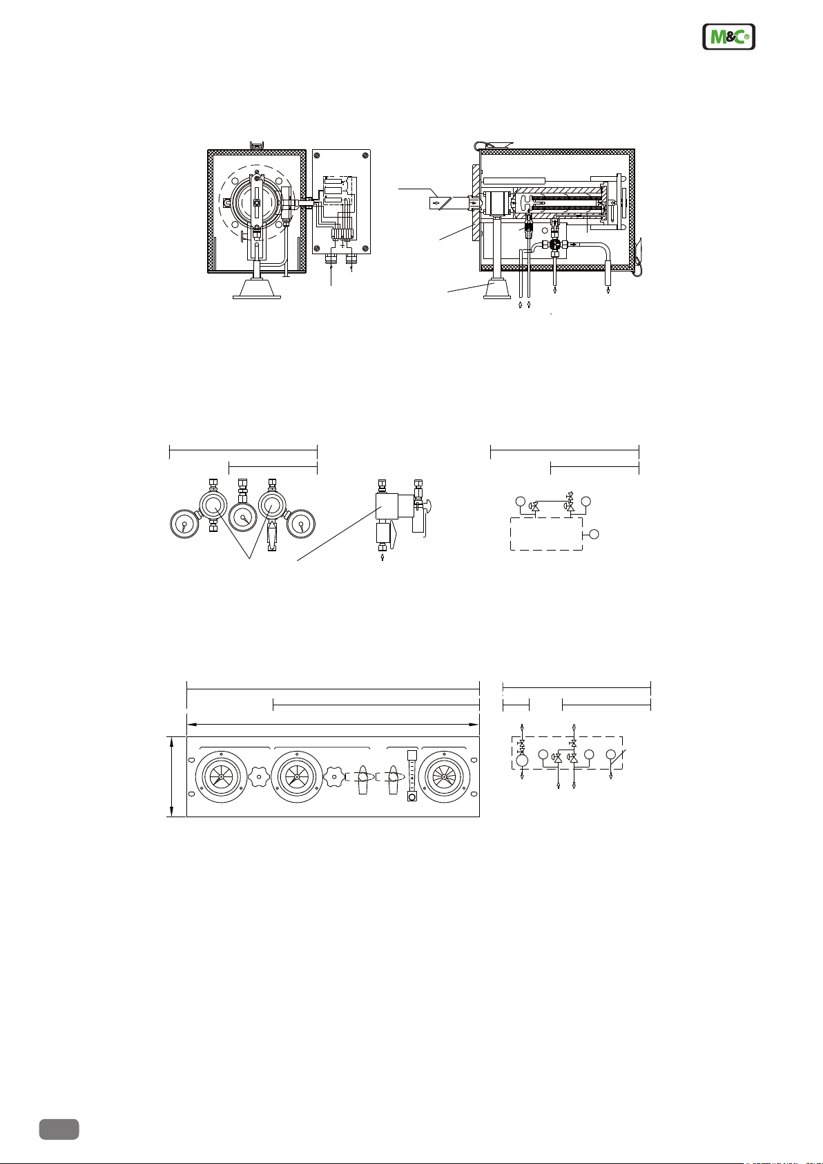
Dimensions
Pressure regulator
-A
-A1-A1
-A
-1...0 bar
measuring point
SP2000H/DIL...
0-6bar
PI
Dilution gas
0-6bar
PI
PI
Underpressure
Bypass Dilution gas
Vacuum pressure
-1...0 bar
2)1)
(ANSI 3" 150lbs) (a)
Ball value -VA
DN65 PN6
Optional,
alarm contact
Temperature
(115V, 60Hz) (a)
230V, 50Hz
Power in
Dilution gas in
Test gas in
Vacuum pressure gauge
-1...0 bar
Sample gas out 3)
To >+30 C
0-180 C
Tu <-30 C
Tsoll
1 673'542
LNL
98
2-1.5.1
see leaflet
Gas sample dilution probe version SP2000H/DIL-VA
1) Calibration gas valve
2) Position of bypass connection
3) Tube ø 8 mm, (5/16“) use at injector I tube connector 8 mm (5/16“) and at II 8-12 mm (5/16-1/2“)
Option -A / -A1 pressure control set
Option -S / -S1 external control panel
Gas connections
dilution gas, test gas, pressure control, bypass gas: ø 6 mm or on request 1/4“ (a)
sample gas out: ø 8 or 12 mm or on request ø 5/16“ or 1/2“ (a)
Dimensions in mm
5.1
M&C TechGroup Germany GmbH • Rehhecke 79 • 40885 Ratingen • Germany
info@mc-techgroup.com • www.mc-techgroup.com • Fon +49 2102 935-0 • Fax +49 2102 935-111
Technical specications and illustrations are without
obligation, subject to modications. 08.99/06.06
Page 3

Dilution gas
measuring point
sample gas out
Underpressure
180° C
Test gas
Underpressure
measuring point
Test gas
320°C
Dilution gas
sample gas out
not present
with type *
-B
-BR
Bypass gas in
*
Sample gas Dilution gas
Underpressure
measuring point
180°C
Sample gas out
Underpressure
measuring point
Sample gas
180°C
Dilution gas
Sample gas out
Bypassgas out
Function Diagrams
SP2000H/DIL
SP2000H320/DIL
SP2000H/DIL-VA
Test gas Dilution gas
180° C
Underpressure
measuring point
Sample gas out
SP2000H/DIL-B* -BR*
SP2000H/DIL-VA-B
SP2000H/DIL-VA-BV
Technical Data
Series SP
Insitu sample tubes and pre filters optional on request see leaflet 2-1.1a; 2-1.5.1; 2-1.6.1; 2-1.9.5
Dilution rates with the critical orifices ”a“ - ”g“
Sample flow rate depending on the critical orifices ”a“ - ”g“ a = 1,4 b = 2,7 c = 5,5 d = 11 e = 19* f = 28 g = 55 l/hr
Possibility to adapt the dillution factror with dillution gas pressure-adjustment -5% to +30%
Dillution gas flow rate with injector version I or II I: 480 - 600Nl/hr, optional for higher dilution rates II: 1800-3000 Nl/hr
Dilution gas pressure on inlet of pressure controller min. 4,5 bar g, max. 16 bar g
Bypass injector /B: gas pressure-gas flow rate-sample gas flow rate at approx. 2 bar g - injector gas approx. 300 l/hr - sample gas approx. 150 l/hr
Process pressure 0,9 up to 2 bar abs.
Fault caused by process temperature variations operation independent from process temperature
Fault caused by process under- or overpressure no fault as long as the differential pressure ∆P at the dilution unit is >0,5 bar g and test gas
Fault caused by atmospheric pressure variations <1% with a variation of 50 mbar
Materials in contact with the sample gas stainless steel 316 / 316Ti, quartz glass, FPM, graphite
Weight approx. 20 kg
*Standard, others to be indicated along with order, intermediate values possible. 1) approx. at 3 bar dilution gas behind pressure controller. 2) -5% not possible for orice „g“. 3) with injector version I. Further technical data see leaet SP2000, 2-1.1a.
®
3)
Version gas sample dilution probe SP2000H/DIL ...
a = 500 b = 200 c = 100 d = 50 e = 30* f = 20 g = 10 : 1
1)
2)
is given to the probe under process conditions
Part No. Type M&C gas sample dilution probe SP2000H/DIL .... with orifice ”e“ for dillution ratio 30 : 1 standard
20 S 4002 SP2000H/DIL dilution probe 180 °C without ball valve upstream of the filter element
20 S 4102 SP2000H320/DIL dilution probe 320 °C without ball valve upstream of the filter element
20 S 4005 SP2000H/DIL-VA dilution probe 180 °C with heated manual operated ball valve upstream of the filter element
20 S 4022 SP2000H/DIL-B dilution probe SP2000H/DIL with bypass injector and bypass gas to the vent
20 S 4024 SP2000H/DIL-BR dilution probe SP2000H/DIL with bypass injector and bypass recirculation
20 S 4026 SP2000H/DIL-VA-B dilution probe SP2000H/DIL-VA with bypass injector and bypass gas to vent
20 S 4030 SP2000H/DIL-VA-BV dilution probe SP2000H/DIL-VA with bypass-needle valve and bypass gas to vent
20 S 4200 SP2000H/DIL-A option: 1 pressure controller, 2 gauges, mounting set incl. connector set for dilution probe
20 S 4210 SP2000H/DIL-A1 option: 2 pressure controllers, 3 gauges, mounting set incl. connector set for dilution probe with bypass
20 S 4250 SP2000H/DIL-S option: control panel with 1 pressure controller, 2 gauges, flowmeter, 2 ball valves
20 S 4260 SP2000H/DIL-S1 option: control panel with 2 pressure controllers, 3 gauges, flowmeter, 2 ball valves
Please set an (a) after the part no. for dilution probe with power 115V 60Hz, mounting ange ANSI 3" 150lbs or for connectors with inches dimensions.
Part no. 20 S 4300 : compl. set critical orice a-g , injector orice II , orice seals
control panel -S, -S1 incl. wall mounting housing optional available: -S-G, -S1-G.
Other versions on request.
Technical specications and illustrations are without
obligation, subject to modications. 08.99/06.06
M&C TechGroup Germany GmbH • Rehhecke 79 • 40885 Ratingen • Germany
info@mc-techgroup.com • www.mc-techgroup.com • Fon +49 2102 935-0 • Fax +49 2102 935-111
5.1
 Loading...