

Page 1
Operating instructions
®
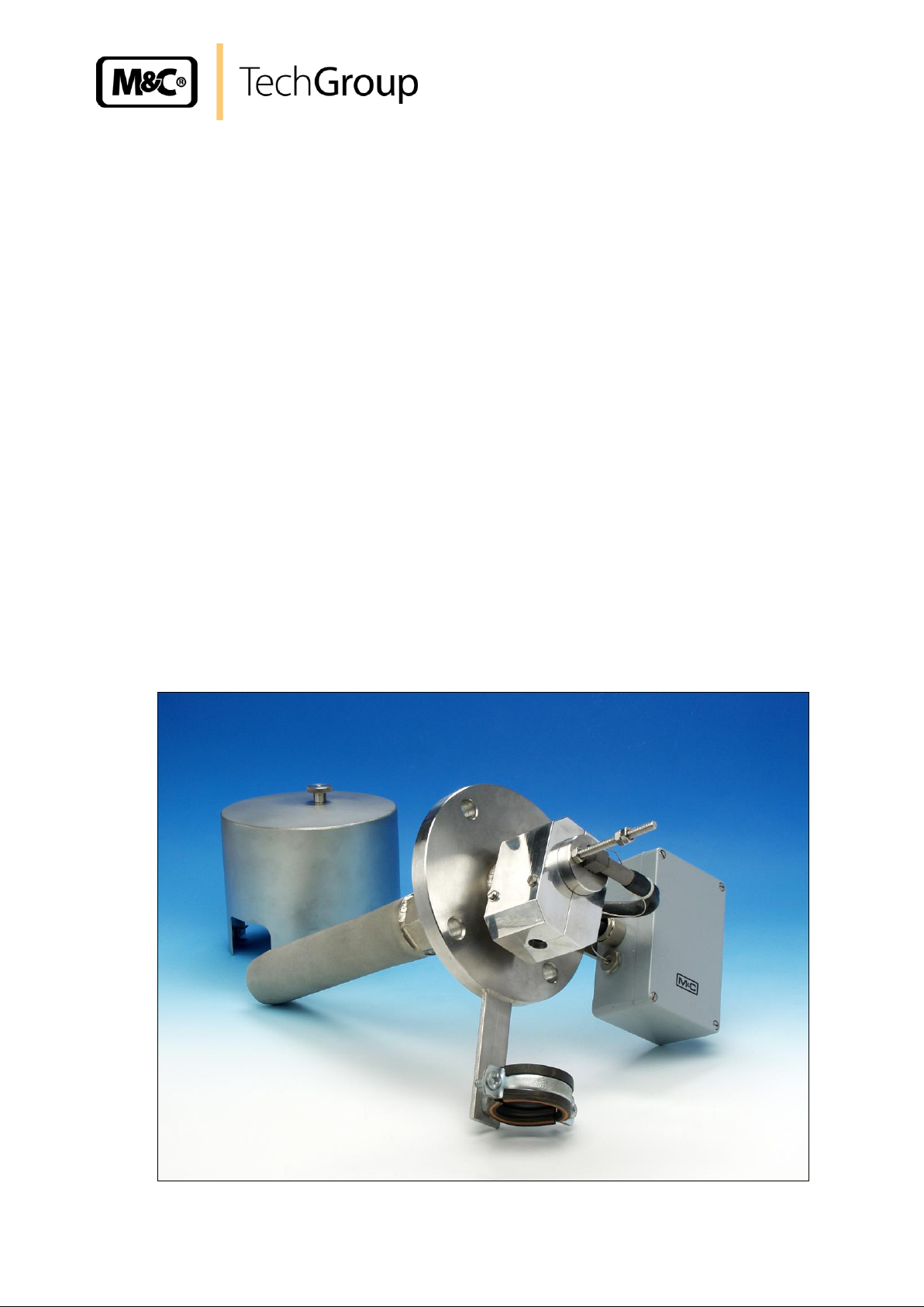
Gas sample probe Serie SP
Version SP10, SP10-H
Gas sampling and gas conditioning technology 2-0.1.1-ME
Page 2

2
This Operating Manual does not claim completeness and may
be subject to technical modifications.
© 10/2004 M&C TechGroup Germany GmbH. Reproduction of
this document or its content is not allowed without permission from
M&C.
SP® is a registered trade mark.
2nd edition 06/2008
Dear customer,
we have made up this operating manual in such a way that all necessary information about the product can be found and understood quickly and easily.
Should you still have any question, please do not hesitate to contact M&C directly or go through your
appointed dealer. Respective contact addresses are to be found in the annexe to this operating manual.
Please also contact our homepage www.mc-techgroup.com for further information about our products. There, you can read or download the data sheets and operating manuals of all M&C products as
well as further information in German, English and French.
Gas sampling and gas conditioning technology 2-0.1.1-ME
Page 3

3
Content
1 General information ..................................................................................................................... 4
2 Declaration of conformity ........................................................................................................... 4
3 Safety instructions ....................................................................................................................... 5
4 Warranty ....................................................................................................................................... 5
5 Used terms and signal indications ............................................................................................. 6
6 Introduction .................................................................................................................................. 7
7 Technical Data ............................................................................................................................. 7
8 Application ................................................................................................................................... 7
9 Description ................................................................................................................................... 8
10 Probe design ................................................................................................................................ 8
11 Receipt of goods .......................................................................................................................... 9
12 Preparation for Installation ....................................................................................................... 10
13 Mounting ..................................................................................................................................... 10
14 Electrical connections ............................................................................................................... 11
15 Start up ....................................................................................................................................... 12
16 Maintenance ............................................................................................................................... 13
17 Closing down ............................................................................................................................. 13
18 Spare parts list ........................................................................................................................... 14
19 Appendix .................................................................................................................................... 14
List of illustrations
Figure 1 Dimensions SP10-H ............................................................................................................. 9
Figure 2 Electrical connection SP10-H ............................................................................................. 12
Gas sampling and gas conditioning technology 2-0.1.1-ME
Page 4

4
Head Office
M&C TechGroup Germany GmbH Rehhecke 79 40885 Ratingen Germany
Telephone: 02102 / 935 - 0
Fax: 02102 / 935 - 111
E - mail: info@mc-techgroup.com
www.mc-techgroup.com
1 GENERAL INFORMATION
The product described in this operating manual has been examined before delivery and left our works
in perfect condition related to safety regulations. In order to keep this condition and to guarantee a
safe operation, it is important to heed the notes and prescriptions made in this operating manual. Furthermore, attention must be paid to appropriate transportation, correct storage, as well as professional installation and maintenance work.
All necessary information a skilled staff will need for appropriate use of this product are given in this
operating manual.
2 DECLARATION OF CONFORMITY
CE - Certification
The product described in this operating manual complies with the following EC directives:
EMV-Instruction
The requirements of the EC directive 2004/108/EC “Electromagnetic compatibility“ are met.
Low Voltage Directive
The requirement of the EC directive 2006/95/EC “Low Voltage Directive“ are met.
The compliance with this EC directive has been examined according to DIN EN 61010.
Declaration of conformity
The EU Declaration of conformity can be downloaded from the M&C homepage or directly requested
from M&C.
Gas sampling and gas conditioning technology 2-0.1.1-ME
Page 5

5
3 SAFETY INSTRUCTIONS
Please take care of the following basic safety procedures when mounting, starting up or operating this
equipment:
Read this operating manual before starting up and use of the equipment. The information and warnings given in this operating manual must be heeded.
Any work on electrical equipment is only to be carried out by trained specialists as per the regulations
currently in force.
Attention must be paid to the requirements of VDE 0100 (IEC 364) when setting high-power electrical
units with nominal voltages of up to 1000 V, together with the associated standards and stipulations.
Check the details on the type plate to ensure that the equipment is connected to the correct mains
voltage.
Protection against touching dangerously high electrical voltages:
Before opening the equipment, it must be switched off and hold no voltages. This also applies to any
external control circuits that are connected.
The device is only to be used within the permitted range of temperatures and pressures.
Check that the location is weather-protected. It should not be subject to either direct rain or moisture.
The equipment must not be used in hazardous areas.
Installation, maintenance, monitoring and any repairs may only be done by authorized personnel with
respect to the relevant stipulations.
4 WARRANTY
If the equipment fails, please contact M&C directly or else go through your M&C authorised dealer.
We offer a one year warranty as of the day of delivery as per our normal terms and conditions of sale,
and assuming technically correct operation of the unit. Consumables are hereby excluded. The terms
of the warranty cover repair at the factory at no cost or the replacement at no cost of the equipment
free ex user location. Reshipments must be send in a sufficient and proper protective packaging.
Gas sampling and gas conditioning technology 2-0.1.1-ME
Page 6

6
DANGER!
This means that death, severe physical injuries and/or important
material damages will occur in case the respective safety measures are not fulfilled.
WAR N I N G !
This means that death, severe physical injuries and/or important
material damages may occur in case the respective safety measures are not fulfilled.
CARE!
This means that minor physical injuries may occur in case the respective safety measures are not fulfilled.
CARE!
Without the warning triangle means that a material damage may
occur in case the respective safety measures are not met.
AT T E N T I O N !
This means that an unintentional situation or an unintentional status
may occur in case the respective note is not respected.
NOTE!
These are important information about the product or parts of the
operating manual which require user’s attention.
SKILLED STAFF
These are persons with necessary qualification who are familiar with
installation, use and maintenance of the product.
5 USED TERMS AND SIGNAL INDICATIONS
Gas sampling and gas conditioning technology 2-0.1.1-ME
Page 7

7
Series SP
®
Version SP10
Version SP10-H
Part No.
01 S 1000
01 S 2000
System of protection
IP54 EN60529
Sample temperature
V10 max.600°C * optional HC max. 900 °C
Sample pressure
0,4 bis 6 bar abs.*
Ambient temperature
-20°C bis +60°C
Dust load
max. 10 g/m3 *, optional higher 10 g/m
3
Insitu probe length
270 mm*
Heater temperature adjustable
+100 bis +200°C, optional with PT100 without controller
Ready for operation
after 1 h
Sample gas outlet connection
1/8"-NPT internal for tube connectors max. 10mm
Power supply
230V/50Hz / 240V/60Hz 315W, optional
115V/60Hz 300W
Electrical connection
terminals max 4mm2, 1x PG13,5 cable gland
Electrical equipment standard
EN60529/61010, EN 60519-1
Mounting flange
DN65 PN6, Form B , rostfr. Stahl 1.4571
Material of sample connecting parts
SS316, SS316Ti, Novapress*
Weight
4 kg
6 INTRODUCTION
M&C gas sample probes provide direct insitu ultra-fine filtration during continuous gas sampling for
analytic measurements. In this way, part of the necessary maintenance work for a system is concentrated on a single point. This filter technology has the major advantage that dust mixtures consisting of
ultra-fine and coarse dusts can be optimally retained with the least possible maintenance work.
Optimal adaptation of the M&C gas sample probe to processing conditions and to measurement work
is a necessary condition for a measurement system to work smoothly. Basically, the gas sample
should be kept to a necessary minimum. This is made possible thanks to optimised downstream gas
processing using M&C components. Only in this way it is possible to reduce maintenance to a minimum while ensuring maximum availability.
7 TECHNICAL DATA
* Standard
** In case of higher ambient temperatures use option PT100 (Part No. 20S9025) or thermocouple Fe-CuNi respectively Ni-CrNi (Part No.
20S9027 resp. 20S9028) instead of the thermostat controller. Then, an additional electronic temperature controller (see data sheet 2-5.1) is
necessary.
8 APPLICATION
Gas sampling and gas conditioning technology 2-0.1.1-ME
Page 8

8
NOTE!
Install the probe at a weather-protected sample point. For outdoor applications please use a version with option weather protection shield.
The M&C gas sample probes SP10 respectively SP10-H are used for continuous gas sampling in
processes with dust loadings up to 10g/m3, operating pressures up to max. 6 bar abs., temperatures
up to max. 600C and high gas humidities. The modular design allows the combination of different
pre-filter materials (max. 900°C) and length (>10g/m3) and therefore an optimum adaption to the process conditions. The compact design requires only little space.
9 DESCRIPTION
The M&C gas sample probes are designed for easy installation, reliable operation and trouble-free
maintenance. Advantages are:
Gas sampling with dust loaded processes;
Low volume, fast response time;
Different pre-filters as an option.
The gas sample probe is heated up to max. +200C.
10 PROBE DESIGN
The probe head with its all-round heating element forms a unit with the standard mounting flange
DN65 PN6 and the laterally mounted junction box.
A mounting clamp and a 1/8” internal thread are located on the underside of the probe for the connection of heated M&C gas sampling lines with external diameters of 40mm to a max. 55mm and a tube
diameter of max. 10mm.
After assembly of the sample line and the tube connector the sample gas outlet connection is enclosed with the heat conducting shells. The maximum operating temperature for stainless steel prefilters type V10.. is 600C and for the pre-filters V10..HC 900°C.
The modular system of our gas sample probes allows the usage of all M&C pre-filters type V10 and
extension tubes type Vo and Vm with 1” thread. This guarantees an optimal adaptation to the process
conditions.
The following cross-sectional drawing shows the gas sample probe SP10-H.
Gas sampling and gas conditioning technology 2-0.1.1-ME
Page 9

9
46
60
250
130
*225
**555
**600
*270
90
14
**V10-1, V10-2
*V10, V10-0
1"
1/8"NPT
Sample out
Optional with
Volume displacer
Power In
SP 10-H
Terminal box with
thermostat
M&C
Heating element
Heat conductivity shells for
tube fitting
250
NOTE!
The gas sample probe should be removed carefully from the packaging and
checked immediately for completeness against the delivery note. Check the
goods for any damage incurred during transport and if necessary inform
your transport insurer of any damage.
Figure 1 Dimensions SP10-H
11 RECEIPT OF GOODS
The M&C gas sample probe is normally delivered in one unit. It comprehends the gas sample probe
with pre-filter, screws, nuts and flange gasket.
Gas sampling and gas conditioning technology 2-0.1.1-ME
Page 10

10
Weatherproof mounting position
_____present
_____install
Low/overpressure situation
mbar
bar
Process temperature
°C, Min.
°C, Max.
Dust loading
g/m³
Dust composition - grain size
µm
Gas composition
corrosive
toxic
explosive
Parameters to be measured, e.g. 02, CO,
SO2, NOX, ...,
Vol.%
mg/Nm³
ppm
Required gas flow
l/rh, Min.
l/hr, Max.
Required reaction time T90
sec.
12 PREPARATION FOR INSTALLATION
Please pay attention to the following points:
Select the optimal sampling point in accordance with the generally applicable guidelines or consult
the competent persons.
Locate the sampling point in such a way that there is adequate space for inserting and removing
the gas sample probe and pay attention to the insertion length of the probe tube.
Make certain that the gas sample probe is easily accessible so that you can carry out any subse-
quent maintenance work without trouble.
Design and isolate the bleeder connection in such a way that the temperature of the whole connec-
tion is always above the acid dew point in order to avoid corrosion and blockage problems.
If the ambient temperature in the area of the bleeder connection is >80C as a result of radiated
heat, then a radiated heat deflector must be mounted to protect the probe.
The mounting flange at the bleeder connection should comply with DN65 PN6. If other connection
sizes are required, a special adapter flange can be supplied as an option (Part No. 20S9004) .
Before mounting, the gas sample probe must be adjusted to the existing operating conditions. We
recommend to check the existing parameters accordingly to the following table:
13 MOUNTING
M&C SP10 resp. SP10-H gas sample probes are designed for stationary use and if properly selected
and mounted a long service life and maintenance are guaranteed.
It is advisable to mount the gas sample probe in a position which has a 10inclination to the process
(not necessary for the function of the probe ).
Screw the prefilter directly on to the 1” outer thread with the 1” flat gasket and tighten.
If an extension tube is used, it should be mounted between the gas sample probe and the pre-filter.
If the gas sample probe connection does not correspond to the standard flange connection DN65
PN6, then the optionally supplied adapter flange should be mounted to the probe.
Before fixing the gas sample probe at the bleeder connection first attach the flange gasket to the
mounting flange.
The temperature-resistant, stainless steel connectors supplied by M&C have a double-blade ring system to ensure reliable sealing. After tightening the nuts of these connectors by hand, they should then
be tightened exactly 1 1/4 of a turn using a flat spanner and are then properly mounted.
Gas sampling and gas conditioning technology 2-0.1.1-ME
Page 11

11
NOTE!
If a PTFE tube is used as sample line, an insert must be installed in
the end of the tube in order to prevent the tube being pressed together !
WAR N I N G !
When connecting the equipment, please ensure that the supply
voltage is identical with the information provided on the model type
plate!
NOTE!
Attention must be paid to the requirements of IEC 364 (DIN VDE
0100) when setting high-power electrical units with nominal voltages of up to 1000 V, together with the associated standards and
stipulations!
Now place the heat conductivity shells on the connection of the gas sample line and prove it’s fit to
prevent cold spots.
14 ELECTRICAL CONNECTIONS
For the electrical installation take the relevant safety instructions into consideration. Before connecting
the probe ensure that the mains is voltage-free.
The junction box is mounted on the side of the gas sample probe. The wiring plan is located in the lid
of the junction box. A cable bushing is available for the mains cable.
Gas sampling and gas conditioning technology 2-0.1.1-ME
Page 12

Carry out the following steps:
230V 50Hz
(115V 60Hz)
Power
1
2
3
4
L
N
L
315W(300W)
Sensor
Tset
12
Figure 2 Electrical connection SP10-H
Remove the lid of the junction box;
Insert the mains cable (min. 3 x 1.5 mm2) through the cable gland and connect it to the appropri-
ate terminals as in the wiring above;
Screw lid back on;
15 START UP
Before starting up check whether the mains power supply voltage corresponds with the information
stated on the probe’s nameplate.
Switch on mains power supply.
The total heating-up time is approximately 1 hour. The sample gas can now be extracted via the gas
sample probe after this heating-up time.
Gas sampling and gas conditioning technology 2-0.1.1-ME
Page 13

13
WAR N I N G !
Before starting maintenance work on electrical parts ensure that the
mains and the eventually connected alarm and control circuits are
switched off completely!
WAR N I N G !
High surface temperatures. Wear protective gloves!
16 MAINTENANCE
The safety instructions specific to the plant and process are to be consulted prior to any maintenance
work!
Maintenance cycles have to be carried out depending on your process or ambient conditions. An indication for a possible gas sample probe-maintenance could be a constant decline in the amount of
sample gas to the analysis system.
Probe maintenance is restricted essentially on replacing or cleaning the pre-filter. The pre-filter can be
cleaned for example in an ultrasonics bath.
To change or clean the pre-filter the gas sample probe has to be dismounted.
For this loosen the 4 screws at the flange and remove the gas sample probe from the process.
Unscrew pre-filter from the probe body and screw on the new or cleaned pre-filter.
17 CLOSING DOWN
Before switching off, that means switching off the heating, the M&C gas sample probe should be
flushed with inert gas or air in order to avoid condensation of aggressive components from the process
gas. After that, close gas outlet tight.
There are no other precautions to take.
Gas sampling and gas conditioning technology 2-0.1.1-ME
Page 14

14
M&C Gas sample probe SP®10, SP®10-H
(C) Consumable part
(R) Recommended spare parts
(S) Spare parts
Recommended quantity for operation
[years]
Part No.
Description
C/R/S
1 2 3
90 S 1005
Insitu stainless steel filter type V10, without volume
displacer Filter porosity: 2µm, Length: 225mm,
46mm OD, Material: SS316
V
b.d.*
b.d.*
b.d.*
90 S 1010
Insitu hastelloy filter type V10/HC, without volume
displacer Filter porosity: 2µm, Length: 225mm,
46mm OD, Material: hastelloy C4
V
b.d.*
b.d.*
b.d.*
90 S 1012
Insitu hastelloy filter type V10-0/HC, with volume
displacer Filter porosity: 2µm, Length: 225mm,
46mm OD, Material: hastelloy C4
V
b.d.*
b.d.*
b.d.*
90 S 1015
Insitu stainless steel filter type V10-1, with volume
displacer Filter porosity: 2µm, Length: 550mm,
60mm OD, Material: SS316
V
b.d.*
b.d.*
b.d.*
90 S 1016
Insitu hastelloy filter type V10-1/HC, with volume
displacer Filter porosity: 2µm, Length: 550mm,
60mm OD, Material: hastelloy C4
V
b.d.*
b.d.*
b.d.*
90 S 1017
Insitu stainless steel filter type V10-2, without volume displacer Filter porosity: 2µm, Length: 550mm,
60mm OD, Material: SS316
V
b.d.*
b.d.*
b.d.*
90 S 1018
Insitu hastelloy filter type V10-2/HC, without volume
displacer Filter porosity: 2µm, Length: 550mm,
60mm OD, Material: hastelloy C4
V
b.d.*
b.d.*
b.d.*
90 S 1020
Gasket 1" for SP10/11/21/31 V10
E
b.d.*
b.d.*
b.d.*
90 S 2077
Flange gasket DN65 PN6B (67). Material: Novapress
E
b.d.*
b.d.*
b.d.*
90 S 0005
Cartridge heater element for SP10/23H, SP23,
Filter H/H0, L=130mm, 230VAC/315W.
E
b.d.*
b.d.*
b.d.*
90 S 0006
Cartridge heater element for SP10/23H, SP23,
Filter H/H0, L=130mm, 115VAC/300W.
E
b.d.*
b.d.*
b.d.*
90 S 0011
Thermostat 100-300°C for SP21-H/300 probe diameter 8mm.
E
b.d.*
b.d.*
b.d.*
93 S 0018
Temperature resistant heat sink compound, 100g.
E
b.d.*
b.d.*
b.d.*
18 SPARE PARTS LIST
Wear, tear and replacement part requirements depend on specific operating conditions. The recommended quantities are based on experience and they are not binding.
* by demand
19 APPENDIX
More product documentation is available on our Internet catalogue:
www.mc-techgroup.com
Gas sampling and gas conditioning technology 2-0.1.1-ME
 Loading...