

Page 1
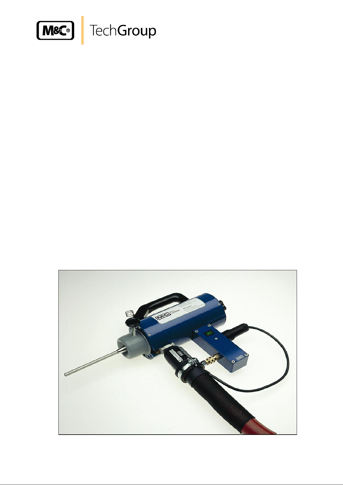
Operating Instructions
Electrically-heated and portable gas sample probes
Series PSP4000-H, PSP4000-H/C, PSP4000-H/C/T
Gas sampling and gas conditioning technology 2-2.1-ME
Page 2

2
This Operating Manual does not claim completeness and may be
subject to technical modifications.
© 03/1996 M&C TechGroup Germany GmbH. Reproduction of this
document or its content is not allowed without permission from M&C.
SP® is a registered trade mark.
2nd Edition: 03/2007
Dear customer,
we have made up this operating manual in such a way that all necessary information about the
product can be found and understood quickly and easily.
Should you still have any question, please do not hesitate to contact M&C directly or go through your
appointed dealer. Respective contact addresses are to be found in the annexe to this operating
manual.
Please also contact our homepage www.mc-techgroup.com for further information about our
products. There, you can read or download the data sheets and operating manuals of all M&C
products as well as further information in German, English and French.
Gas sampling and gas conditioning technology 2-2.1-ME
Page 3

3
Contents
1 General information ....................................................................................................................... 4
2 Declaration of conformity ............................................................................................................. 4
3 Safety instructions ........................................................................................................................ 5
4 Warranty ......................................................................................................................................... 5
5 Used terms and signal indications .............................................................................................. 6
6 Introduction .................................................................................................................................... 7
7 Serial numbers ............................................................................................................................... 7
8 Power supply ................................................................................................................................. 7
9 Technical Data ............................................................................................................................... 8
9.1 Options ..................................................................................................................................... 9
10 Applications ................................................................................................................................. 10
11 Description ................................................................................................................................... 10
12 Receipt of goods .......................................................................................................................... 11
13 Preparation and installation ....................................................................................................... 11
14 Supply connections ..................................................................................................................... 12
14.1 Connecting the heated sample line ........................................................................................ 12
14.2 Electrical connection .............................................................................................................. 13
14.3 Calibration-gas discharge ....................................................................................................... 13
14.4 Temperature measurement .................................................................................................... 14
15 Starting ......................................................................................................................................... 14
16 Maintenance ................................................................................................................................. 15
16.1 Changing the filter element .................................................................................................... 15
17 Switching off ................................................................................................................................ 15
18 Spare parts list ............................................................................................................................. 16
19 Appendix ...................................................................................................................................... 17
List of illustrations
Figure 1 Connection of the heated sample line ................................................................................. 12
Figure 2 Sample facilities .................................................................................................................. 18
Figure 3 Wiring plan .......................................................................................................................... 19
Figure 4 Basic version ....................................................................................................................... 20
Figure 5 Carrying case to transport sample probe ............................................................................ 21
Figure 6 Filter unit and connection of the heated sample line ........................................................... 22
Figure 7 High temperature sample tube aluminium oxide ................................................................. 23
Figure 8 Electrically heated sample tube SP34-H ............................................................................. 24
Gas sampling and gas conditioning technology 2-2.1-ME
Page 4

4
Head Office
M&C TechGroup Germany GmbH Rehhecke 79 40885 Ratingen Germany
Telephone: 02102 / 935 - 0
Fax: 02102 / 935 - 111
E - mail: info@mc-techgroup.com
www.mc-techgroup.com
1 GENERAL INFORMATION
The product described in this operating manual has been examined before delivery and left our works
in perfect condition related to safety regulations. In order to keep this condition and to guarantee a
safe operation, it is important to heed the notes and prescriptions made in this operating manual.
Furthermore, attention must be paid to appropriate transportation, correct storage, as well as
professional installation and maintenance work.
All necessary information a skilled staff will need for appropriate use of this product are given in this
operating manual.
2 DECLARATION OF CONFORMITY
CE - Certification
The product described in this operating manual complies with the following EC directives:
EMV-Instruction
The requirements of the EC directive 2004/108/EC “Electromagnetic compatibility“ are met.
Low Voltage Directive
The requirement of the EC directive 2006/95/EC “Low Voltage Directive“ are met.
The compliance with this EC directive has been examined according to DIN EN 61010.
Declaration of conformity
The EU Declaration of conformity can be downloaded from the M&C homepage or directly requested
from M&C.
Gas sampling and gas conditioning technology 2-2.1-ME
Page 5

5
3 SAFETY INSTRUCTIONS
Please take care of the following basic safety procedures when mounting, starting up or
operating this equipment:
Read this operating manual before starting up and use of the equipment. The information and
warnings given in this operating manual must be heeded.
Any work on electrical equipment is only to be carried out by trained specialists as per the regulations
currently in force.
Attention must be paid to the requirements of VDE 0100 (IEC 364) when setting high-power electrical
units with nominal voltages of up to 1000 V, together with the associated standards and stipulations.
Check the details on the type plate to ensure that the equipment is connected to the correct mains
voltage.
Protection against touching dangerously high electrical voltages:
Before opening the equipment, it must be switched off and hold no voltages. This also applies to any
external control circuits that are connected.
The device is only to be used within the permitted range of temperatures and pressures.
Check that the location is weather-protected. It should not be subject to either direct rain or moisture.
The device must not be used in hazardous areas.
Installation, maintenance, monitoring and any repairs may only be done by authorized personnel with
respect to the relevant stipulations.
4 WARRANTY
If the equipment fails, please contact M&C directly or else go through your M&C authorised dealer.
We offer a one year warranty as of the day of delivery as per our normal terms and conditions of sale,
and assuming technically correct operation of the unit. Consumables are hereby excluded. The terms
of the warranty cover repair at the factory at no cost or the replacement at no cost of the equipment
free ex user location. Reshipments must be send in a sufficient and proper protective packaging.
Gas sampling and gas conditioning technology 2-2.1-ME
Page 6
6
DANGER!
This means that death, severe physical injuries and/or important
material damages will occur in case the respective safety measures
are not fulfilled.
W ARN IN G !
This means that death, severe physical injuries and/or important
material damages may occur in case the respective safety
measures are not fulfilled.
CARE!
This means that minor physical injuries may occur in case the
respective safety measures are not fulfilled.
CAR E!
Without the warning triangle means that a material damage may
occur in case the respective safety measures are not met.
ATT ENT ION !
This means that an unintentional situation or an unintentional status
may occur in case the respective note is not respected.
NOTE!
These are important information about the product or parts of the
operating manual which require user’s attention.
SKILLED STAFF
These are persons with necessary qualification who are familiar with
installation, use and maintenance of the product.
5 USED TERMS AND SIGNAL INDICATIONS
Gas sampling and gas conditioning technology 2-2.1-ME
Page 7

7
6 INTRODUCTION
M&C gas sample probes provide direct insitu ultra-fine filtration during continuous gas sampling for
analytic measurements. In this way, part of the necessary maintenance work for a system is
concentrated on a single point. This filter technology has the major advantage that dust mixtures
consisting of ultra-fine and coarse dusts can be optimally retained with the least possible maintenance
work.
Optimal adaptation of the sample probe to processing conditions and to measurement work is a
necessary condition for a measurement system to work smoothly. Basically, the gas sample should be
kept to a necessary minimum. This is made possible thanks to optimised downstream gas processing
using M&C components. Only in this way is it possible to reduce maintenance to a minimum while
ensuring maximum availability.
7 SERIAL NUMBERS
The nameplates bearing the serial number are located on the side of the electrical connection box.
Always quote the device's serial number when making enquiries and ordering replacement parts.
8 POWER SUPPLY
Depending on the version, the probe is operated with 115 or 230 V AC. Precise details can be found
on the device's nameplate.
Gas sampling and gas conditioning technology 2-2.1-ME
Page 8

9 TECHNICAL DATA
Probe series SP®
portable version
PSP4000
PSP4000-H
PSP4000-H / C
PSP4000-H /C /T
Part No. 230V
40S1000
40S1005
40S1015
Part No. 115V
40S1000a
40S1005a
40S1015a
Sample temperature
max. 600 °C *standard
Sample pressure
max. 1 bar
Ambient temperature
-20 °C to +60 °C
Filtration chamber
volume
40 cm
3
Filter element
S-2K ceramic, 2 μm
Probe temperature
Adjustable between 100-180 °C, pre-set at works to 180°C
Ready for operation
After approximately 30 minutes
Gas inlet
Basic connection G 3/8"i, probe tube or adapters optional
Gas outlet
1/8" NPT + tube connector ø 6 mm (optional ø 8 mm)
and pipe clamp for attachment of heated sample line
Power supply
220-240V 50/60Hz, 200 W or 115V 60Hz
Electrical connection
Plug and socket connector 7 pin with 4 meter connection cable
Electrical equipment
standard
EN 61010, EN 60519-1
System of protection
IP40, EN 60529
Material
Stainless steel 316Ti, ceramic, FPM
Weight
3 kg
Calibration gas
connection for
SS-tube/Plastic
hose ø 6 mm
no
yes
yes
Temperature
measurement with
Thermocouple sensor
FeCuNi, length 600 mm
with 4 m connection
cable and standard plug.
no
no
yes
8
Gas sampling and gas conditioning technology 2-2.1-ME
Page 9

9.1 OPTIONS
Part No.
40S9130
extra price for PSP4000-H.. with sample outlet ø 8 mm tube connector
40S9100
extra price for PSP4000-H /FW with special filter cartridge filled with special spun glass with
M12-connection, material SS316Ti, FPM
sample adapter with variable probe tube length:
40S9005
3/8" adapter fitting with gasket and 8 mm PTFE sealing ring
40S9000
adapter with cone-shaped part for openings of ø 10-20 mm and ø 8 mm probe tube out of
stainless steel 316, extensible 80-200 mm
40S9010
ø 8 mm probe tube out of stainless steel 316Ti with position indication, for extensible probe
length of 190-300 mm.
fixed probe tubes with male connector G 3/8", length 1 m:
40S9020
Material: stainless steel SS316Ti, ø 6 mm, max. 600 °C
40S9030
Material: stainless steel SS316Ti, ø 8 mm, max. 600 °C
40S9040
Material: stainless steel SS316Ti, ø 10 mm, max. 600 °C
40S9050
Material: stainless steel SS316Ti, ø 12 mm, max. 600 °C
40S9108
Material: Titane, ø 6mm, max. 400 °C
40S9109
Material: Hastelloy® C, ø 6/8 mm, max. 900 °C
40S9112
Material: Inconell® 625, ø 12 mm, max. 1200 °C
40S9106
Material: Kanthal®, ø 15 mm, max. 1300 °C
40S9110
Material: Ceramic-Aluminium-Oxyd 1), ø 12 mm, max. 1800 °C, for mounting tube adapter
PSP4000H/AO Art. Nr. 40S9111 is necessary
40S9111
Tube adapter PSP4000H/AO, material: stainless steel SS316Ti
heated sample probe tubes SP34-H...:
40S9115
heated sample probe tube SP34-H with incorporated thermostate
40S9120
heated sample probe tube SP34-H1.1 with thermocouple sensor FeCuNi
40S9125
heated sample probe tube SP34-H2 with PT100 sensor
equipment, out of stainless steel SS316Ti for placing the probe stationary:
40S9060
intermediate connection adapter G3/4"o - G3/8"i / 8 ø with gasket 3/8".
40S9070
connection mounting nipple of R 2"o. DIN 2999/1 with G 3/4"i und G 3/8"i
40S9080
mounting flange DN65 PN6 B with thread connection 3/4"i ISO and gasket
90S2075
flange gasket set for DN65 PN6 B consisting of Klingerit gasket and screws M12
heated sample line PSP4M4/6 spec. made for probe PSP4000H:
01B4034
beginning connection part I with pipe end, for interchangeable tube 4/6, incl. PT100 and 1,5 m
extension cable axial at the back, with 7 pins plug
01B4037
end connection part K with spec. pipe end, for interchangeable tube 4/6, 0,5 m extension cable
axial at the back, with 7 pins connector
01B4036
per meter heated sample line PSP4M4/6, operating temperatures max. 200 °C with
exchangeable PTFE hose 4/6 mm to jut out 0,5 m (cold end), incl. 3 extra wire for the probe
heater, PT100 position 0,6 m mounted from electrical inlet Silicone foam heat insulation with
Nylon net, power 220-240V 50/60Hz, 110W/m
Max. 12 meter length at 230V/50Hz and 6 meter length at 115V/60Hz for PSS-5..-conditioing
system with internal temperature regulator
01B4034W
beginning connection part I for sample line PSP-W4M4/6 with pipe end, for interchangeable tube
4/6, incl. PT100 and 1,5 m extension cable axial at the back, with 7 pins plug
01B4037W
end connection part K for sample line PSP-W4M4/6 with spec. pipe end, for interchangeable
tube 4/6, 0,5 m extension cable axial at the back, with 7 pins connector
01B4036W
per meter heated sample line PSP-W4M4/6, operating temperatures max. 200 °C with
exchangeable PTFE hose 4/6 mm to jut out 0,5 m (cold end), incl. 3 extra wire for the probe
heater, PT100 position 0,6 m mounted from electrical inlet. Silicone foam heat insulation with
corrugated hose envelope out of PA, power 220-240V 50/60Hz, 110W/m.
Max. 10 meter length at 230V/50Hz and 6 meter lenfth at 115V/60Hz for PSS-5..-conditioing
system with internal temperature regulator
40S9090
aluminium-composite carrying case PSP to take portable gas sample probe PSP4000H... and
max. 5 m heated sample line PSP4M4/6 or max. 8 m PSP-W4M4/6, dimension 530 x 420 x 300
mm
9
Gas sampling and gas conditioning technology 2-2.1-ME
Page 10

10
NOTE!
The max. length of heated sample lines for PSS-5 gas conditioning systems
with integrated temperature controller is 12m for 230V/50Hz resp. 6m for
115/60Hz.
10 APPLICATIONS
The PSP4000-H... gas sample probes are used for extraction of gases from dust loaded, high-
temperature or humid processes.
Due to its compact design and low weight, the device is envisaged particularly for mobile uses. The
basic probe including the compact sample adapter with variable probe tube lengths enable rapid and
centric gas sampling from, for example, exhaust gas pipes with diameters of between 150 mm and
600 mm.
A probe tube with a fixed length of 1 meter extends the range of potential applications.
With version PSP4000-H/C/T, parallel to gas sampling it is also possible to measure the process
temperature at the end of the probe tube using an integrated thermo-couple sensor.
To avoid cooling and condensation of sample gas in the extraction area, a heated sample probe tube
SP34-H.. is available.
Appropriate accessories are available for mounting the probes directly at the flange or threaded
sleeve-mounting brackets.
The specially designed, electrically-heated sample lines PSP 4M4/6 or PSP-W4M4/6 with reduced
outer diameter can be connected to the PSP4000-H... for transporting gas to the gas sample
conditioning system.
If unheated sample lines are used, this should be conducted on a descending gradient to the gas
sample conditioning system.
11 DESCRIPTION
The standard version is as follows:
The stainless steel filter chamber (SS316Ti) with an integrated 2µm ceramic depth filter element is
inserted completely into an electrically heated aluminium heating jacket with a heat-insulated
protective casing.
The temperature is adjusted to + 180°C via an integrated and adjustable capillary tube thermostat.
The green control lamp glows during the heat-up phase and is extinguished when the heating element
temperature is reached. It then comes on and off as the heating element is switched on and off.
By changing the internal wiring, the sample probe can be operated at 230V 50 Hz or 115V 60 Hz. The
standard wiring is for 230V.
Electrical connection is effected at the connection socket on the probe via the power cable provided
with a 7-pin adapter jack or via an additional cable conducted within the heated sample line PSP
4M4/6 resp. PSP-W4M4/6 , also with a 7-pin adapter jack.
The adapter jack's pins are wired as follows:
Pin 3: L - Mains power line conductor.
Pin 4: N - Mains power neutral conductor.
Pin 7: PE - Protective earthing conductor.
The probe's sample gas outlet connection has a 1/8" NPT inner thread. A temperature resistant 6 mm
tube connector is fitted gas-tight into this to connect the sample line. Once the electrically-heated
sample line PSP 4M4/6 resp. PSP-W4M4/6 has been mounted, the connection is enclosed in special
heat-conducting jaws in order to avoid temperatures falling below the required level in the critical
connection areas.
Gas sampling and gas conditioning technology 2-2.1-ME
Page 11

11
The heated sample line is rapidly and safely mechanically coupled with a tightening bracket including
integrated quick-coupling.
To ensure simple filter changes, the complete filter unit including the connected sample line can be
drawn out of the heat-insulated protective casing.
In the PSP400H/C special version, calibration-gas into the probe is possible without disassembling
the probe via a special threaded connecting joint.
The special version PSP4000H/C/T allows the process temperature to be measured by way of a
thermo-element which is introduced into this threaded connecting joint. Its length can be adjusted up
to the end of the sampling tube. The standard length of this thermocouple sensor is 600 mm.
Optionally available is the PSP transport case for transporting the PSP4000-H... gas-sample probe
including a maximum 5 m heated sample line PSP 4M4/6 resp. max. 8m for type PSP-W4M4/6.
12 RECEIPT OF GOODS
The gas sample probe PSP4000-H... is normally delivered in two packaging units:
1. Basic gas-sample probe with optional mounting accessories.
2. Optional sample tubes.
The gas sample probe should be removed carefully from the packaging and checked immediately for
completeness against the delivery note.
Check the goods for any damage incurred during transport and if necessary inform your transport
insurer of any damage.
13 PREPARATION AND INSTALLATION
Select the optimal sampling point in accordance with the generally applicable guidelines or consult the
competent persons.
The sampling point should be easily accessible.
Locate the probe connections in such a way that the connections' temperature is always above the
acid dew point in order to avoid corrosion and blockage problems.
If the ambient temperature in the area of the connections is >80°C as a result of radiated heat, then a
radiated-heat deflector must be mounted to protect the probe.
The probe can also be mounted with an optional mounting flange or R2" threaded mounting fitting.
Before mounting, the probe must be adjusted to the existing operating conditions.
Gas sampling and gas conditioning technology 2-2.1-ME
Page 12

12
Under / over pressure situation
mbar
bar
Process temperature
°C,
Min.
°C,
Max.
Dust loading
g/m³
Dust composition - grain size
µm
Gas composition
corrosive
toxic
explosive
Which parameters should be
measured, e.g. O2, CO, SO2, NOX,....,
Vol.%
mg/Nm³
ppm
Required amount of gas
l/h,
Min.
l/h,
Max.
Necessary T90 time
sec.
Heated sample line
PTFE-tube DN 4/6
The existing operational parameters are to be checked accordingly prior to commencing mounting
work.
14 SUPPLY CONNECTIONS
14.1 CONNECTING THE HEATED SAMPLE LINE
Remove the aluminium heat-conducting jaws at the probe's filter head by loosening the 4
screws from the gas outlet's threaded connection. The outlet's threaded connection is provided
for the connection of a tube with an external diameter of 6 mm (optionally 8 mm).
Before connecting a sample line not specified by M&C, the tube connection should be
prepared according to the following sketch.
M&C's heated sample lines type PSP 4M4/6 and PSP-W4M4/6 are manufactured to fit the
mechanical and electrical connections to the PSP4000-H... gas sample probe and already contain an
internal line for the probe's power supply.
Figure 1 Connection of the heated sample line
Push the insert into the PTFE tube in order to avoid the tube being compressed and slide the
red silicon protective ring up to the end of the heated sampling tube.
Introduce the PTFE tube into the threaded connection joint with the double-cutting ring system
to ensure sealing.
Gas sampling and gas conditioning technology 2-2.1-ME
Page 13

13
After tightening the connecting nuts by hand, tighten them a further 1 1/4 turns using a flat
spanner.
Push the end of the heated sample line as far as the end of the threaded connection joint and
clamp with the aluminium heat-conducting jaws.
Mount the aluminium heat-conducting jaws in the longitudinal axis of the filter chamber in such
a way that they fit into the aperture in the heat-insulated protective casing.
Remove the front part of the tension clip for holding the heated sampling tube to the probe and
push the filter chamber including the heated sampling probe into the heat-insulated protective
casing.
Screw on the front part of the tension clip again.
In the case of the PSP4000-H screw down the black knob on the rear side of the protective
casing and tighten by hand.
In the case of the PSP4000-H/C, PSP4000-H/C/T, the flat nut and the dummy bolt of the
threaded connecting joint on the rear side are to be screwed on again and after tightening the
dummy bolt by hand, this is then to be tightened further by turning precisely 1 1/4 turns with a
flat spanner.
14.2 ELECTRICAL CONNECTION
Plug in the 7-pin plug (power supply) and switch on the power. During the heating up phase,
the green control lamp glows. When the operating temperature is reached (180°C), the green
control light is extinguished and then lights up when the heating element is switched on to
adjust the temperature.
For safety reasons, we recommend switching the gas pump on only after another fifteen
minutes has elapsed in order to ensure that the sampling probe heats up completely.
When using the SP34-H... heated sample tube, the electrical connection should be made separately
using the built-in connection socket. The SP34-H sample tube has a built-in capillary tube thermostat
which adjusts the temperature in a range between 100°C and 180°C. (Factory setting 180°C).
When using the heated sample tube SP34-H1.1 and SP34-H2, an external temperature controller is
to be used for adjusting the temperature.
14.3 CALIBRATION-GAS DISCHARGE
In the case of the probe version PSP400-H/C with integrated calibration-gas connection, test gas can
be conducted directly into the probe during the entire sampling procedure for the calibration of
connected gas-analysis devices.
Remove the threaded connection's dummy bolt on the rear side of the probe.
Connect the 6 mm stainless steel tube provided or a temperature resistant tube DN4/6 (PTFE,
viton, silicon) using the nut provided and the double clamping ring. When connecting the tube,
prior to assembly the 4 mm stainless steel insert must be pushed into the tube.
Introduce the tube or the hose into the threaded connection until it clicks in.
Tighten the threaded connection's nuts by hand and then exactly 1 1/4 turn using a flat
spanner.
Gas sampling and gas conditioning technology 2-2.1-ME
Page 14

14
ATT ENT ION !
The protective housing's surface temperature is around 50°C.
NOTE!
Push the sample tube into the connecting adapter up to the marking as
otherwise the conical seal ring will not have a sealing effect.
14.4 TEMPERATURE MEASUREMENT
In the case of the probe version PSP4000-H/C/T, after removing the dummy bolt, the thermo-
element is pushed into the threaded connection on the rear side of the probe and fixed and
sealed using the connecting nut and the PTFE conical ring seal.
The thermo-element can be adjusted to the length of the sampling tube by sliding it backwards
and forwards accordingly.
Tighten the nut by hand and then carefully tighten further using an open-end wrench until the
thermo-element sits firmly.
The external measuring amplifier or an extension compensation lead is to be connected to the
compensating lead's standard plug.
15 STARTING
If a transport case is in use, remove the probe along with the heated sample line connected. Connect
the sample line to the gas sample conditioning system.
1. Connection of the PTFE tube connection
2. Connection of the 7-pin plug.
When using the device for the first time and when connecting the heated sample line, proceed as
follows:
In the case of the PSP4000-H, draw the probe's filter chamber forwards out of heat-insulated
protective casing by loosening and removing the black knob (rear side).
In the case of the PSP4000-H/C, PSP4000-H/C/T, the dummy bolt and the flat nut located on
the rear side of the threaded connection must be loosened and removed to do this.
Then mount the desired probe option at the filter chamber's G3/8" inlet:
In case of option "probe with adjustable tube length", screw the connecting adapter including
its integrated PTFE conical ring seal 40S9005 with washer into the probe's G3/8" inlet thread.
Push the heat-insulated adapter with its cone connector 40S9000 over the connection
adapter's pressure nut and fix it to the nut with the clamping screw.
Push the 8 mm sample tube through the conical connection into the filter chamber.
By turning the adapter to the right, the PTFE conical ring seal is pressed together and thus
seals the sampling tube.
When using a SP34H... heated sample tube, this should be screwed into the probe's G3/8" inlet
threaded connection. Additional unheated sample tubes or pre-filters can be screwed into the G3/8"
threaded connection at the other end as the need arises.
When mounting the probe in conjunction with the threaded fitting 40S9070, and flange 40S9080, the
connecting adapter with the PTFE conical ring seal 40S9005 and the intermediate adapter G3/4" 8mm 40S9060 are to be used.
Gas sampling and gas conditioning technology 2-2.1-ME
Page 15

15
ATT ENT ION !
High surface temperatures! Wear protective gloves!
ATT ENT ION !
In case of a hot probe wear protective gloves when changing the filter
element.
16 MAINTENANCE
It is difficult to give any recommendations as to a particular maintenance cycle. Depending on your
process conditions, a meaningful maintenance cycle must be elaborated for the specific application.
An indication that probe-maintenance may be necessary could be shown by a constant decline in the
amount of sample gas in the analysis system.
Probe maintenance is restricted essentially to replacing filter elements and checking seals.
16.1 CHANGING THE FILTER ELEMENT
As far as possible, the filter element should be changed when the probe is cold.
To do this in the case of the PSP4000-H, screw off the black knob on the rear side.
In the case of the PSP400-H/C with sample-gas connection and PSP4000-H/C/T with temperature
measurement the dummy bolt on the rear side is first to be removed and the thermo-element drawn
out. Then loosen and remove the threaded connection's hexagon nut.
Now loosen the rapid coupling for the heated sample line holder by pressing down on the outside
coupling ring and draw the complete filter unit out of the heat-insulated protective casing.
Screw the screw-on sleeve off the filter head.
Screw off the filter element holder and replace the filter element.
Check the filter element seals and the O-ring at the filter head and replace if necessary.
Clean filter chamber.
Clean or rod through the sampling tube in order to remove any deposits.
Then re-assemble in reverse order.
17 SWITCHING OFF
Before switching off, i.e. switching off the heating, the probe should be flushed with inert gas or air in
order to avoid condensation of aggressive components from the process gas.
Gas sampling and gas conditioning technology 2-2.1-ME
Page 16

16
Portable gas sample probe PSP4000-H..
(C) Consumables parts
(R) Recommended spare parts
(S) Spare parts
Recommended quantity being in
operation [years]
Part No.
Description
C/R/S
1 2 3
90 S 0015
Filter element S-2K,ceramic 2µm [4]
C
6 12 24
94 S 0005
Spun glass cartridge FW for PSP4000
S
- 1 1
93 S 2083
Filter spun glass, pure, temp. resistant up to 690°C, 500g
C
1 2 3
93 S 0045
Viton-gasket [3] for PSP4000
R
4 8 12
90 F 0040
Viton-O-ring 26 [2]
R
2 4 8
94 S 0045
Novapress gasket 3/8" (blue), max. 600°C
R
3 6 9
90 S 2078
Ceramic fibre gasket 3/4“, max. 1250°C
R
1 1 1
90 S 2080
Novapress gasket 3/4" (blue), max. 600°C
R
1 1 1
90 S 2077
flange gasket DN65 PN6 B, Novapress (67mm i.d.)
S
- - -
94 S 0040
PTFE fix ring, for 3/8“ fitting P.No. 40 S 9005
R
2 4 5
94 S 0050
Thermostat 100-180°C with 6mm sensor tube
R
- 1 1
93 S 0018
Temperature resistant heat sink compound,
max. 200°C, 100 g tube
R 1 1
1
94 S 0010
Cartridge heater 230V 160W, PSP4000 up to S.No. 118
R 1 1 2 94 S 0015
Cartridge heater 115V/230V 100W
R 2 2 4 94 S 0025
Tube connection 6mm for PSP4000-H/C
S - -
-
94 S 0020
Blind cap compl. for PSP4000-H/C
S - - - 94 S 0030
VITON o-ring 3 for PSP4000-H/C blind cap
R 2 4 6 94 S 0035
PTFE fix ring for PSP4000-H/C/T thermoelement connection
R 2 4
6
18 SPARE PARTS LIST
Wear, tear and replacement part requirements depend on specific operating conditions.
The recommended quantities are based on experience and they are not binding.
Gas sampling and gas conditioning technology 2-2.1-ME
Page 17

17
19 APPENDIX
Sample facilities, PSP4000-H/C and PSP4000-H/C/T
Wiring plan
Basic version
Carrying case to transport sample probe
Filter unit and connection of the heated sample line
High temperature sample tube aluminium oxyde
Electrically heated sample tube SP34-H
Further product documentation can be seen and downloaded from our home page:
www.mc-techgroup.com
Data sheet – portable heated sample probe PSP4000-H
Document: 2-2.1
Data sheet - electrically heated sample probe tube SP34-H
Document: 2-2.2
Gas sampling and gas conditioning technology 2-2.1-ME
Page 18

18
Figure 2 Sample facilities
Gas sampling and gas conditioning technology 2-2.1-ME
Page 19

19
Figure 3 Wiring plan
Gas sampling and gas conditioning technology 2-2.1-ME
Page 20

20
Figure 4 Basic version
Gas sampling and gas conditioning technology 2-2.1-ME
Page 21

21
Figure 5 Carrying case to transport sample probe
Gas sampling and gas conditioning technology 2-2.1-ME
Page 22

22
Figure 6 Filter unit and connection of the heated sample line
Gas sampling and gas conditioning technology 2-2.1-ME
Page 23

23
Figure 7 High temperature sample tube, aluminium oxide
Gas sampling and gas conditioning technology 2-2.1-ME
Page 24

24
Figure 8 Electrically heated sample tube SP34-H
Gas sampling and gas conditioning technology 2-2.1-ME
 Loading...