

Page 1
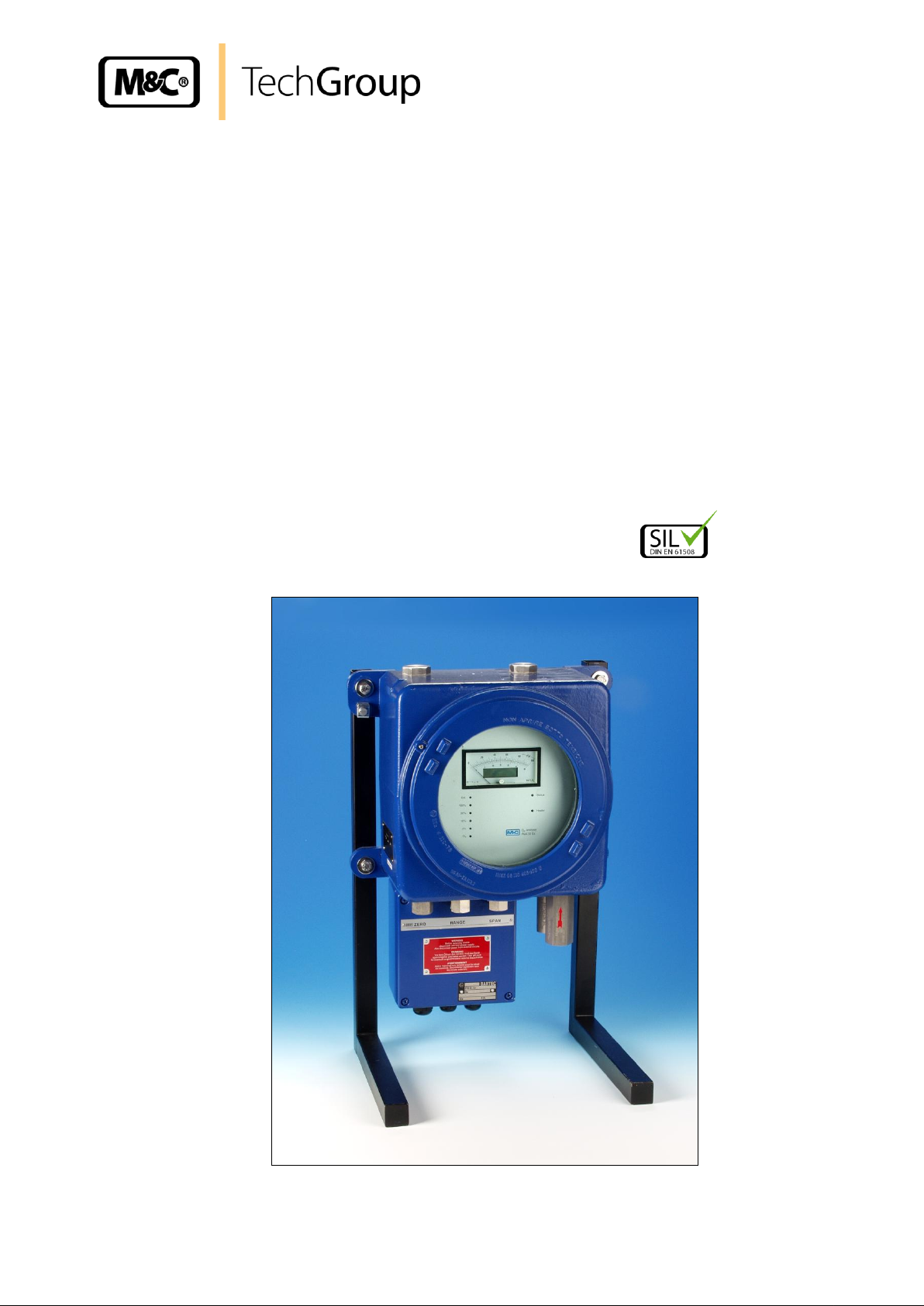
Operating Manual
Oxygen Analyser Series PMA
Version PMA 50 Ex
Gas sampling and gas conditioning technology 9-3.15-ME
Page 2

2
This Operating Manual does not claim completeness and may be
subject to technical modifications.
© 04/1996 M&C TechGroup Germany GmbH. Reproduction of this
document or its content is not allowed without permission from M&C.
PMA® is a registered trade mark.
6th Edition: 12/2011
Dear customer,
we have made up this operating manual in such a way that all necessary information about the
product can be found and understood quickly and easily.
Should you still have any question, please do not hesitate to contact M&C directly or go through
your appointed dealer. Respective contact addresses are to be found in the annexe to this operating manual.
Please also contact our homepage www.mc-techgroup.com for further information about our
products. There, you can read or download the data sheets and operating manuals of all M&C
products as well as further information in German, English and French.
Gas sampling and gas conditioning technology 9-3.15-ME
Page 3

3
List of Contents
1 General information ......................................................................................................... 5
2 Declaration of conformity ................................................................................................ 5
3 Electrical standards ......................................................................................................... 6
4 Safety instructions ........................................................................................................... 6
5 Information and safety instructions for using the Analyser in hazardous areas ......... 7
6 Warranty ........................................................................................................................... 7
7 Used terms and signal indications .................................................................................. 8
8 Introduction ...................................................................................................................... 9
8.1 Serial number ............................................................................................................... 9
8.2 Power supply ................................................................................................................ 9
9 Application ....................................................................................................................... 9
10 Technical Data ................................................................................................................ 10
10.1 Options ....................................................................................................................... 11
11 Description ..................................................................................................................... 12
11.1 PMA 50 Ex/P/PD-1-50 with pressure compensation and enclosure purging (without
SIL-certification) .......................................................................................................... 13
11.2 PMA 50 Ex/P/PD with pressure compensation (without SIL-certification) .................... 14
11.3 Option zero suppression (without SIL-certification) ..................................................... 14
11.4 Option enclosure purging or ventilation ....................................................................... 14
12 Measuring principle ....................................................................................................... 15
13 Gas flow diagram ........................................................................................................... 16
14 Receipt of goods ............................................................................................................ 18
15 Installation ...................................................................................................................... 18
16 Supply connections ....................................................................................................... 19
16.1 Sample gas inlet and sample gas outlet ...................................................................... 19
16.2 Option purging enclosure or ventilation ....................................................................... 19
16.3 Electrical connection ................................................................................................... 20
17 Starting up ...................................................................................................................... 21
18 Calibration ...................................................................................................................... 21
18.1 Zero calibration ........................................................................................................... 22
18.2 Span calibration .......................................................................................................... 23
19 Measuring ....................................................................................................................... 25
20 Cross sensitivities ......................................................................................................... 26
21 Closing down .................................................................................................................. 29
22 Storage and Transport ................................................................................................... 29
23 Maintenance ................................................................................................................... 29
23.1 Removal of the measuring cell .................................................................................... 30
23.2 Mechanical zero point adjustment ............................................................................... 33
24 Spare parts list ............................................................................................................... 34
25 Appendix......................................................................................................................... 35
Gas sampling and gas conditioning technology 9-3.15-ME
Page 4

4
List of Illustrations
Figure 1 PMA 50 Ex Oxygen Analyser ................................................................................. 12
Figure 2 Scheme of the measuring cell and optical signal processing .................................. 15
Figure 3 Gas flow diagram ................................................................................................... 16
Figure 4 Gas conditioning .................................................................................................... 17
Figure 5 Electrical connection in the connection box of the PMA 50EX EEX e ..................... 20
Figure 6 Schematic view of the internal layout of the analyser ............................................. 30
Figure 7 Transmitter unit ........................................................................................................ 32
Figure 8 Schematic view of the transmitter unit .................................................................... 33
Figure 9 Circuit diagram front board PMA50ex 10.2008 ....................................................... 38
Figure 10 Assembly front board PMA50ex 10.2008 ............................................................... 39
Figure 11 Circuit diagram mains adapter PMA50ex 10.2008 .................................................. 40
Figure 12 Assembly / connection mains adapter PMA 50ex 10.2008 ..................................... 41
Figure 13 Cut-out magnification front board for adjustment of temperature alarm (TP10,
P19) (TP11: actual temperature) und flow alarm threshold (P20) ............................ 42
Figure 14 Cut-out magnification front board couple sensor bridge for application of a
transmitter without couple sensor ........................................................................... 42
Figure 15 Cut-out magnification front board for adjustment of reference voltage ,
amplification and offset of the O2-signal .................................................................. 43
Figure 16 Cut-out magnification mains adapter for adjustment of the temperature, current
and voltage output .................................................................................................. 44
Figure 17 Cut-out magnification mains adapter for adjustment of burden and limitation of
the current output ................................................................................................... 44
Gas sampling and gas conditioning technology 9-3.15-ME
Page 5

5
Head Office
M&C TechGroup Germany GmbH Rehhecke 79 40885 Ratingen Germany
Telephone: 02102 / 935 - 0
Fax: 02102 / 935 - 111
E - mail: info@mc-techgroup.com
www.mc-techgroup.com
1 GENERAL INFORMATION
The product described in this operating manual has been examined before delivery and left our
works in perfect condition related to safety regulations. In order to keep this condition and to
guarantee a safe operation, it is important to heed the notes and prescriptions made in this operating manual. Furthermore, attention must be paid to appropriate transportation, correct storage,
as well as professional installation and maintenance work.
All necessary information a skilled staff will need for appropriate use of this product are given in
this operating manual.
2 DECLARATION OF CONFORMITY
CE - Certification
The product described in this operating manual complies with the following EC directives:
ATEX-Directive
The product described in this manual is produced in accordance with the EC directive for devices and
protection systems for appropriate use in hazardous areas 94/9/EG appendix II.
EMV-Instruction
The requirements of the EC directive 2004/108/EG “Electromagnetic compatibility“ are met.
Low Voltage Directive
The requirement of the EC directive 2006/95/EG “Low Voltage Directive“ are met.
Declaration of conformity
The EU Declaration of conformity can be downloaded from the M&C homepage or directly requested from M&C.
The SIL –declaration of conformity can be requested directly at M&C.
Gas sampling and gas conditioning technology 9-3.15-ME
Page 6

6
3 ELECTRICAL STANDARDS
The electrical standard of electrical equipment corresponds to the safety regulations concerning
the EN61010 and to the safety requirements of the European standards EN 61508; EN 50014 :
1997, EN 50018 : 2000, EN 50019 : 2000, EN 50020 : 2002 and EN 50284 : 1999 for operation of
the equipment in hazardous areas group II category 2. Attention must be paid to the Certificate of
Conformity KEMA 03 ATEX 2215X (see appendix).
4 SAFETY INSTRUCTIONS
Please note the following basic safety procedures when using this equipment:
Read these operating instructions carefully before start-up and use of the equipment! The
information and warnings given in these operating instructions must be heeded.
Attention must be paid to the requirements of the certificate of conformity (see appendix):
KEMA 03 ATEX 2215X.
Work on electrical equipment is only to be carried out by trained specialists as per the
regulations currently in force.
Attention must be paid to the requirements of VDE 0100 when setting high-power electri-
cal units with nominal voltages of up to 1000V, together with the associated standards
and stipulations.
For use in hazardous area observe the relevant national and international instructions and
regulations.
Check the details on the type plate to ensure that the equipment is connected up to the
correct mains voltage.
Protection against touching dangerously high electrical voltages. Before opening the
equipment, it must be switched and hold no voltages. This also applies to any external
control circuits that are connected.
The equipment is only to be set within the permitted range of temperatures and pres-
sures.
Check that the location is weather-protected. It should not be subjected to either direct
rain or moisture.
Installation, maintenance, monitoring and any repairs may only be done by authorised
personnel with respect to the relevant stipulations.
Gas sampling and gas conditioning technology 9-3.15-ME
Page 7

7
5 INFORMATION AND SAFETY INSTRUCTIONS FOR USING THE ANALYSER
IN HAZARDOUS AREAS
The Oxygen Analyser PMA 50 Ex is suitable for use in hazardous area group II category 2.
The explosion proof protection is:
II 2G EEx de IIC T5 or II 1/2 G EEx de [ia] IIC T5 KEMA (appr.-no.: 03 ATEX 2215X)
The analyser has been certified through KEMA, authorized company for official approval of electric
equipment in the Netherlands. Detailed information and a copy of the certificate are attached to this
operating manual.
Installation and operation of the analyser has to be done corresponding to the conditions in the Excertificate (see appendix). Only in this case, the reliability of operation in hazardous area can be guaranteed.
All changes of the standard analyser with parts which are not specified or approved by M&C as well as
repair and service with not specified parts mean a loss of the Ex-certificate.
In case of doubt, please turn directly to M&C respectively to your M&C franchised dealer.
6 WARRANTY
If the equipment fails, please contact M&C directly or else go through your M&C authorised
dealer.
We offer a one year warranty as of the day of delivery as per our normal terms and conditions of
sale, and assuming technically correct operation of the unit. Consumables are hereby excluded.
The terms of the warranty cover repair at the factory at no cost or the replacement at no cost of
the equipment free ex user location. Reshipments must be se nd in a sufficient and proper p rote ctive packaging.
Gas sampling and gas conditioning technology 9-3.15-ME
Page 8
8
DANGER!
This means that death, severe physical injuries and/or important material
damages will occur in case the respective safety measures are not fulfilled.
W ARN I NG !
This means that death, severe physical injuries and/or important material damages may occur in case the respective safety measures
are not fulfilled.
CARE!
This means that minor physical injuries may occur in case the respective safety measures are not fulfilled.
CA R E!
Without the warning triangle means that a material damage may occur in case the respective safety measures are not met.
AT T ENT ION !
This means that an unintentional situation or an unintentional status
may occur in case the respective note is not respected.
NOTE!
These are important information about the product or parts of the
operating manual which require user’s attention.
SKILLED STAFF
These are persons with necessary qualification who are familiar with
installation, use and maintenance of the product.
NOTE!
These are important information about the product or parts of the
instruction manual referring to operating in hazardous areas.
7 USED TERMS AND SIGNAL INDICATIONS
Gas sampling and gas conditioning technology 9-3.15-ME
Page 9

9
8 INTRODUCTION
8.1 SERIAL NUMBER
The type plate with the serial number is fixed on the left side of the analyser’s housing.
Please indicate always this serial number in case of questions or when purchasing spare parts.
8.2 POWER SUPPLY
The internal power supply of the Oxygen Analyser PMA 50 Ex is reversible 115/230V AC, with
40Hz to 60Hz. Exact indications are to be found on the type plate. Variations of the power supply
of -15% to +10% do not effect the function of the analyser.
9 APPLICATION
The Oxygen Analyser PMA 50 Ex is suitable for the continuous measurement of oxygen in particle-free and dry sample gases with a maximum dew point of 5°C.
The features of the anaylser are safe operation, accuracy and low maintenance.
The measurement is based on the physical principle of the magneto-dynamic oxygen measuring
cell and is one of the most exact quantitative methods of oxygen determination within the range
of 0-100 Vol.% oxygen.
There is a direct flow against the measuring cell which has got a low volume of only 2 ml (small
stagnant volume). Further characteristics are robustness, extremely small drift, fast response
time (T90 < 5 sec.) and negligible cross sensitivities to other sample gas components.
Flow variations within a range of 0 Nl/h to 60 Nl/h air result in a changement of the oxygen indication which is smaller than 0,2 Vol % O2.
Measurements in flue gases and in inerting installments are some typical applications for the
PMA 50 Ex within a great variety of other measurement tasks.
Gas sampling and gas conditioning technology 9-3.15-ME
Page 10

10 TECHNICAL DATA
Part Number
05A1000 :
05A1000a :
05A2500 :
05A2500a
05A2505 :
05A2505a :
PMA 50 EX, power supply 230V
PMA 50 EX, power supply 115V
PMA 50 EX/P/PD-1-50, power 230V, (not with SIL-certification)
pressure compensation 0,6 - 1,5 bar abs. with purging the enclosure via
two certified ventilate arrestors in the in- and outlet NPT1/4“i
PMA 50 EX/P/PD-1-50, power 115V, (not with SIL-certification)
pressure compensation 0,6 - 1,5 bar abs. with purging the enclosure via
two certified ventilate arrestors in the in- and outlet NPT1/4“i
PMA 50 EX/P/PD, power 230V, (not with SIL-certification)
pressure compensation 0,6 - 1,1 bar abs.
PMA 50 EX/P/PD, power 115V, (not with SIL-certification)
pressure compensation 0,6 - 1,1 bar abs.
Power supply
230VAC (standard) or 115VAC (a) -15% to +10%, 40-60Hz, 35,5VA
Electrical connections
via EEx e connection box 3x PG-cable gland
cable diameter : 6mm - 13mm (M20x1,5), 10mm - 17mm (M25x1,5)
terminals 2,5mm2,
(power, signals, range position and remote choice, status signal)
Measuring ranges
selectable for 0-1, 0-3, 0-10, 0-30 and 0-100 vol.% O2 linear
choice via rotary selection switch at PMA 50 or remote switching
External range indication
Potential free contact for all measuring ranges.
Capacity 48V DC 200mA DC,
Minimum contact rating 5V/1mA
Remote range selection
Measuring ranges selectable via potential free contacts max. 30V DC
3mA DC. The function is displayed at the PMA 50 via LED.
Combined analogue/digital indicator
analogue meter with a scale of 0-30 and 0-100% for each selected range
digital meter 4 1/2 digit 9 mm high LCD-indicator for 0-100% O2 reading,
selectivity 0,01vol.% O2
Output signals
0/4-20mA burden 270 Ω for every measuring range, electrically isolated;
output voltage max. 15V (ex works).
Switchable max. burden 800 Ω, output voltage max. 30V.
Output current limiting adjustable 20mA-22mA (20,5mA ex works)
0-10V DC, burden >100 KΩ for range 0-100 % isolated.
Response time for 90% FSD
< 5 seconds at 60 Nl/hr air
Accuracy after calibration
1% of the span value of measuring range after calibration or 0,02%O
2
depending on which value is the higher one
Reproducibility
Analogue output = < 1% of measuring range / digital indication =
± 0,01 Vol.% O2
Influence of ambient temperature
No influence up to 50 °C
Influence of barometric pressure
The oxygen reading varies in direct proportion to changes of the barometric pressure.
No influence from 0,6-1,5 bar abs. at PMA 50 EEX/P/PD-1-50 with
process pressure compensation
Influence of sample gas flow
Variation in gas flow between 0-60 Nl/hr air will cause a difference of
< 0,2 vol.% O2
Sample gas inlet pressure
0,01-0,1 bar g standard or in case of purging up to 0,5 bar g
(PMA 50 EEX required admission pressure for competent flow rate, no
pump inside)
Sample gas outlet pressure
outlet of analyser must discharge freely into atmosphere
or 0,6-1,5 bar abs. at version PMA 50 EEX/P/PD-1-50 with process pressure compensation
Flow rate of sample gas
Min. 10 Nl/hr up to max. 60 Nl/hr adjustable externally via flow meter (no
flowmeter inside)
Temperature of sample gas
-10 °C up to +50 °C dry gas
O2-transmitter temperature
fixed at +55 °C
10
Gas sampling and gas conditioning technology 9-3.15-ME
Page 11
Temperature cutoff
at 72°C via thermal fuse, non-reversible
Ambient temperature
During operation between -10° C to + 50° C
Storage temperature
-20°C to +60°C at relative air moisture of 0-90% r.h.
Medium touched material
Platine, glass, PTFE, PVDF, stainl. steel 1.4571, Epoxy
Connections measuring gas
Ventilate arrestors at inlet and outlet, NPT 1/4" i
Flow failure
thermo-conductive flow sensor downstream mounted after measuring cell
Status signal outlet
Change-over contact, switching capacity 250 V AC 2A AC, 48V DC
200mA DC minimum contact rating 50mW for temperature <+45°C /
>+60°C, defect light beam, measuring cell not coupled, flow failure
<5 / >80Nl/h, power supply error control, mains voltage breakdown,
failure measuring range selection
Housing / colour
EEX-d e wall mounted explosion-proof housing / blue
Dimensions/Weight
475 (535mm with ventilate arrestors) x 355mm x 200mm (HxWxD) / 22kg
Classification/Protection
II 2G EEx de IIC T5 or II 1/2 G EEx de [ia] IIC T5
IP54 DIN 60529
Certificate No.
KEMA 03 ATEX 2215X
Part
number
Options
05A9015
Zero suppression in range of 1%-97%; Only in connection with part no. 05A2500(a)
PMA50EEx/P/PD-1/50. Externally switchable via potential free contacts, 30V DC 3mA DC
(not with SIL-certification)
05A9005
Extra charge for one ventilate arrestor for PMA-50Ex... for pressure range up to 1500mbar abs.
and non-corrosive gases, connection NPT1/4"i.
05A9000
purging the enclosure via two certified ventilate arrestors, for pressures up to max. 1,5 bar abs.
and/or corrosive gases, connection 1/4" NPTi, purge gas inlet pressure max. 100 mbar, flow
rate 10-60 Nl/hr
Transmitter for measurements of gases from ex-zone 0 II 1/2 G EEx de [ia] IIC T5
90A0009
Measuring cell type PMC-1LB, solvent resistant.
90A0006
Measuring cell PMC-1G with glass solder. O-ring made of Chemraz
10.1 OPTIONS
11
Gas sampling and gas conditioning technology 9-3.15-ME
Page 12
12
130
70
60
200
355
520
2
3
4
571
6
8
9
10
111213
141516
11 DESCRIPTION
The main part of the PMA 50 Ex is the magneto-dynamic oxygen measuring cell.
This measuring principle is one of the most precise quantitative methods for determination of the
oxygen contents in the range of 0-100 Vol.% O2.
The Oxygen Analyser PMA 50 Ex is destined for stationary operation. The mounting into a EEx
de IIC T5 housing 1 with ventilate arrestors in the sample gas inlet and outlet 6 makes it possible
to install the analyser in hazardous area of group II category 2. Equipment with protection (s. type
plate) II 1/2 G EEx de [ia] IIC T5 (option) is suitable to measure explosive gases of group II
category 1.
The analyser is thermostated and regulated to a transmitter temperature of +55°C. The temperature controller is built in that way that the low-voltage part is separated from the 230V capacity
part via an optoelectronic coupler with no-voltage releasing magnet.
A fast and homogeneous conduction of temperature is guaranteed by large-surface heating elements mounted on the transmitter surface.
An overheating of the transmitter to more than 72°C is avoided by a non-reversible thermal fuse.
The transmitter is equipped with an isolating cap in order to accumulate the heat and isolate the
transmitter.
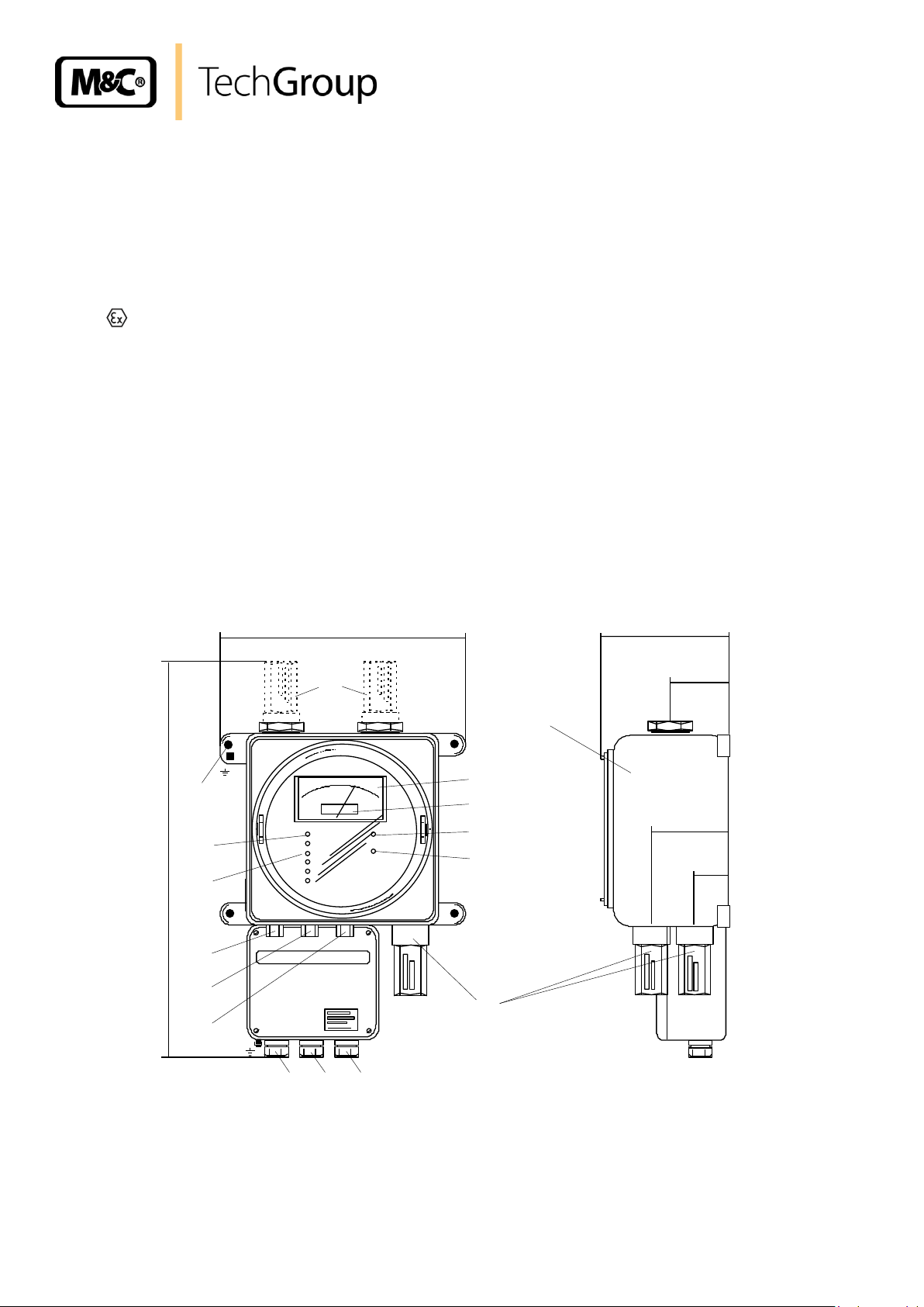
Figure 1 shows the Oxygen Analyser PMA 50 Ex in front view and side view.
Figure 1 PMA 50 Ex Oxygen Analyser
A window in the housing of the analyser enables you to control the indications of the measured
value 2, the status LEDs 4 and 5 as well as the measuring range LEDs 13 and 14.
Gas sampling and gas conditioning technology 9-3.15-ME
Page 13

13
NOTE!
The enclosure purging has to flow off atmospherically free!
Every operational control is accessable from outside and guarantees a simple and user-friendly
handling during calibration and change-over of the measuring range.
The operational controls are:
Adjustment of measuring range span value 10,
Range switch 11 and
Adjustment zero point 12.
The oxygen display of the PMA 50 Ex is effected by a two-scale analogue instrument 2, with
ranges of 0-30 Vol% and 0-100 Vol % O2. A digital display 3 is integrated into the analogue display. Here, the oxygen value is indicated in a range of 0-100Vol% with a resolution of 0,1Vol%.
The change-over of the measuring range is to be done via the range switch 11. The measuring
range chosen is displayed by a respective LED 13 on the front plate of the PMA 50 Ex and via a
potential free contact (see Fig. 5) to external.
The selection of the measuring range can also be effected externally. The LED 14 on the front
plate of the analyser signals the remote measuring range control in connection with a respective
measuring range LED.
The functioning of the analyser heating is indicated by the flashing LED 5.
The PMA 50 Ex has got a collective status output as standard. This is a potential-free change-
over contact in ‘Safety-First’ switching. The breaking capacity is 200mA with 48V DC or 2A with
250V AC. The state is displayed via status-LED 4. The following status signals are given:
Light source defective,
measuring cell not coupled,
flow failure <5 / >80Nl/h,
power supply error control,
mains voltage breakdown,
transmitter temperature <+45°C / >+60°C,
failure measuring range selection
11.1 PMA 50 EX/P/PD-1-50 WITH PRESSURE COMPENSATION AND ENCLOSURE PURGING (WITHOUT SIL-CERTIFICATION)
In case of barometric or process originated pressure variations, the PMA 50 Ex can be equipped
with a special pressure compensation. The compensation can be effected within a pressure
range of 0,6 – 1,5 bar abs.. Thereby errors in measurement caused by pressure variations can
be eliminated.
Additionally the analyser is equipped with an enclosure purging via ventilate arrestors in the inlet
and outlet. The enclosure purging is necessary in case of corrosive sample gas and / or pressure
above 1,1 bar abs.. In case of a leackage in the analyser pressure can not be built up and in case
of additionally corrosive sample gas the analyser will not be damaged. The necessary purge gas
quantity is 10 – 60 Nl/hr corresponding to the adjusted sample gas quantity and the purge gas
inlet pressure is max. 100 mbar.
Gas sampling and gas conditioning technology 9-3.15-ME
Page 14

14
NOTE!
For excess pressure operation (>100 mbar) an enclosure ventilation according to the ex-certificate is necessary. For additionally corrosive
sample gas an enclosure purging is necessary. Both have to flow off
atmospherically free!
11.2 PMA 50 EX/P/PD WITH PRESSURE COMPENSATION (WITHOUT SILCERTIFICATION)
In case of barometric or process originated pressure variations, the PMA 50 Ex can be equipped
with a special pressure compensation. The compensation can be effected within a pressure
range of 0,6 – 1,1 bar abs.. Thereby errors in measurement caused by pressure variations can
be eliminated.
11.3 OPTION ZERO SUPPRESSION (WITHOUT SIL-CE RTIFICATION)
A zero suppression is possible for devices with pressure compensation within a range of 1% to
97% O2. The suppressed measuring range depending on the suppression is lying on the position
of a standard measuring range. The factory provided adjusted suppression can be switched on
and off via an actuator at the terminals 22 resp. 23 inside of the connection box of the analyser
(see Fig. 5). After switching off the original measuring range again is active.
11.4 OPTION ENCLOSURE PURGING OR VENTILATION
For measurement of corrosive gases it is recommandable to equip the analyser with an enclosure
purging. This reduces the risk of a destruction of the analyser by corrosion in case of leaky gas
ways. For this please choose option part number 05A9000 ( 2 x ventilate arrestors). The necessary purge gas quantity is 10 – 60 Nl/hr corresponding to the adjusted sample gas quantity and
the purge gas inlet pressure is max. 100 mbar.
In case of elevated inlet pressure of 1,1bar up to max. 1,5bar abs. also one ventilate arrestor
according to the ex-certificate (see appendix) is required. For this choose option with part number
05A9005. For elevated inlet pressure of 1,1bar up to max. 1,5bar abs. and corrosive sample gas
the analyser has to be equipped with option part number 05A90000 (enclosure purging). The
necessary purge gas quantity is 10 – 60 Nl/hr corresponding to the adjusted sample gas quantity
and the purge gas inlet pressure is max. 100 mbar.
Gas sampling and gas conditioning technology 9-3.15-ME
Page 15
15
2 4 3
1
GAS INLET
GAS OUTLET
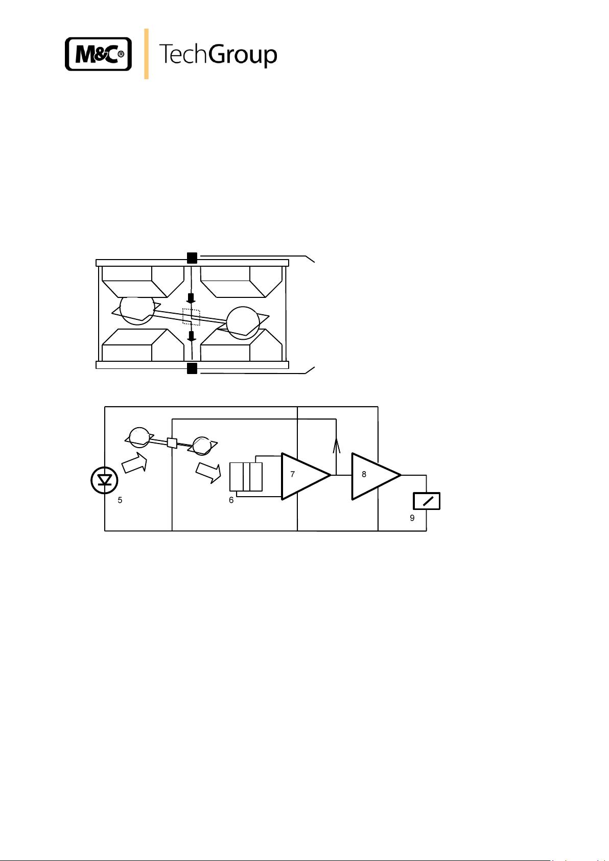
12 MEASURING PRINCIPLE
Oxygen is a gas with a significant paramagnetic susceptibility. The molecules of oxygen are attracted much more strongly by a magnetic field than the molecules of other gases.
The measuring principle shown in the following is benefitting from these characteristics of the
oxygen. The great advantage of the paramagnetic measuring principle is the highly reduced cross
sensitivity of the measurement to other components in the sample gas.
Figure 2 shows the diagram of the measuring cell as well as the optical system for the detection
of the dumbbell’s movement.
Figure 2 Scheme of the measuring cell and optical signal processing
The measuring cell consists of two nitrogen-filled spheres which are arranged in the form of a
dumbbell. In the dumbbell’s central point of rotation, a small mirror is placed. The dumbbell is
surrounded by a wire coil needed for the compensation procedure. The described system is fixed
rotationally symmetrical inside a glass tube via a tightening strap out of platinum and is srewed
up with two pole pieces .
Two permanent magnets are producing an inhomogeneous magnetic field. When oxygen is flowing in, the molecues of the oxygen are drawn into the magnetic field. In consequence, the lines of
electric flux on the cuneiform pole pieces are compressed. The nitrogen-filled diamagnetic
sheres are pushed out of the magnetic field. This causes a rotation of the dumbbell. The rotation
is detected via an optical system consisting of mirror , projection LED and photoelectric cell
.
In case the dumbbell is pushed out of the magnetic fieild, the tension of the photoelectric cell is
immediately changed. The measuring amplifiers and are producing a respective current
which develops via the wire coil on the dumbbell an electro-magnetic load moment. The load
moment is resetting the dumbbell into its zero position.
Gas sampling and gas conditioning technology 9-3.15-ME
Page 16

16
1 : External fine filter
2 : External flow meter
3 : Ventilate arrestor
4 : Measuring cell
5 : Flow alarm sensor
6 : Ventilate arrestor
3
4
5
6 2 1
Every change of the oxygen concentration produces a lineary proportional change of the compensation current and can be read directly in % O2 as oxygen value on the display .
Due to its very small stagnant volume (2 cm3) and the direct flow of the M&C measuring cell, an
extremely fast response time (T90-time) of 1 second for a high gas flow can be realized.
13 GAS FLOW DIAGRAM
Figure 3 shows the gas flow diagram of the Oxygen Analyser PMA 50 Ex.
Figure 3 Gas flow diagram
The measuring cell 4 must absolutely be protected against dust particles. Therefore, the preceding external gas conditioning system should be equipped with a fine filter 1 of at least 2 micron
filter porosity (eg. type FP-2T).
The maximum gas flow of 60Nl/h is adjusted via an externally mounted flow meter 2 with needle
valve.
The sample gas enters the measuring cell 4 via the inlet ventilate arrestors 3.
A flow sensor 5 in the outlet of the measuring cell is controlling the gas flow through the cell ac-
cording to the measuring principle of thermal conductivity. In case the minimum gas flow is decreased, an alarm is automatically given and is available as status alarm on the the collective
status output. Furthermore, an alarm state is shown by a colour change of the LED 4 (see figure
1) on the front plate of the analyzer.
Gas sampling and gas conditioning technology 9-3.15-ME
Page 17

17
1 4 5 9 2
3
8
10 7 6
1
2
5 3 10
Sample
gas outlet
Sample gas
Condensate
I Atmospheric pressure
II Overpressure
Max 100 mbar
Max 100 mbar
8
1 Gas cooler 7 Pressure display
2 Fine filter 8 Overflow valve
3 Flow meter 6-60Nl/h 9 Condensate pump
4 Sample gas pump 10 Analyser PMA50 Ex
5 Filter 11 Condensate removal
6 Pressure reduction
Sample
gas outlet
11
Figure 4 shows the construction of the conditioning system according to above mentioned specification.
Figure 4 Gas conditioning
Gas sampling and gas conditioning technology 9-3.15-ME
Page 18

18
NOTE!
The oxygen analyser PMA 50 Ex must be stored in a wheather - protected and frost-proof area !
W ARN I NG !
The sample gas must be dry (dew point 5°C), free from dust and the
sample gas temperature is not allowed to exceed 50°C. Otherwise
an upstream sample gas cooler with automatic condensate removal
is necessary.
A preceding fine filter of at least 2 micron is absolutely necessary.
The sample gas has to flow off atmospherical freely at the sample gas outlet, because a pressure rise at the sample gas outlet
and therefore in the measuring cell falsifies the oxygen indication.
The maximum inlet pressure is 1,1 bar abs. For the standard device
and 1,5 bar abs. for devices with purging enclosure or ventilation.
NOTE!
The analyser is suitable for use in explosive atmosphere group II
category 2. Equipment with protection II 1/2 G EEx de [ia] IIC T5
is suitable to measure explosive gases of group II category 1.
Equipment with protection II 1/2 G Eex de IIC T5 is suitable to
measure explosive gases of group II category 2.
14 RECEIPT OF GOODS
The analyser PMA 50 Ex is a completely pre-installed unit.
Please take the analyser and possible special accessories carefully out of the packaging mate-
rial immediately after arrival, and compare the goods with the items listed on the packing list;
Check the goods for any damage caused during delivery and, if necessary, notify your trans-
port insurance company without delay of any damage discovered.
15 INSTALLATION
The analyser PMA 50 Ex is designed for stationary wall mounting. All electrical connections are
located inside the connecting box below the analyser housing.
Accurate and proper installation as well as a preceding optimal sample gas conditioning system
will result in a long operatability and a minimum maintenance.
When using the analyser outdoors, it must be protected against atmospheric influences.
The installation should be done in constant climatic ambient conditions if possible.
The ideal installation site should be free from vibration. If this is not possible, rubber-metal con-
nections must be mounted in order to decouple the housing.
The analyser must not be installed in direct proximity of heat sources.
Gas sampling and gas conditioning technology 9-3.15-ME
Page 19

19
W ARN I NG !
The Ex-approval of the oxygen analyser is only valid in connection
with the approved ventilate arrestors. For this reason, it is not allowed to remove them or to use other types of ventilate arrestors !
NOTE!
Please mount the ventilate arrestors with LOCTITE™ type 270 to
anticipate unwanted loosening of the devices !
16 SUPPLY CONNECTIONS
16.1 SAMPLE GAS INLET AND SAMPLE GAS OUTLET
The sample gas inlet and outlet are placed on the lower side of the analyzer. Both are equipped
with ventilate arrestors type MC 95 A. The certified ventilate arrestors are executed with 1/4“ NPT
inside thread.
The sample gas must be dry and free from dust. The sample gas inlet temperature should not
exceed 40°C. Otherwise, a preceding gas cooler with automatic condensate collection is recommended.
The sample gas should escape atmospherically from the outlet if possible, because a pressure
increase inside the measuring cell would falsify the oxygen indication. The maximum inlet pressure is 100mbar.
The sample gas quantity should be adjusted according to local circumstances between 6Nl/h and
60 Nl/h air (external flow meter).
16.2 OPTION PURGING ENCLOSURE OR VENTILATION
According to the Ex-Certificate (see annexe) purging of the enclosure is also requested in case of
increased inlet pressures of 1,1 to max. 1,5 bar. Please choose option part no. 05A9005 respectively with increased pressure and corrosive gases option purging enclosure part no. 05A9000.
When measuring corrosive gases, it is advisable to equip the analyser with the possibility of purging enclosure. This reduces the risk of distruction of the analyser due to corrosion in case of
leaky gas ways. For this please choose option part no. 05A9000 (2 x ventilate arrestor).
The flush gas inlet and outlet are placed on the upper side of the analyser housing. They too, are
both equipped with ventilate arrestors of type MC 95 A with 1/4“ NPTi-connections 16 (see figure
1, broken line).
Dry air or nitrogen has to be used for purging the enclosure. The purge gas flow rate has to be
adjusted between 10Nl/h and 60Nl/h.
Please indicate the option ‘purging enclosure’ with your order !
For a retrofitting of the analyser with the option purging enclosure, the following components are
necessary:
two ventilate arrestors type MC95A, part number 90A5150
1 x male connector DN4/6-1/4““NPTi, part number 05V2060 for the purge gas connection.
Gas sampling and gas conditioning technology 9-3.15-ME
Page 20

20
W ARN I NG !
If you do not use the correct supply voltage, the equipment may be
destroyed. Please take care of the correct supply voltage as indicated on the type plate.
The equipotential bonding terminals of the analyser housing and
the terminal box must always be connected in case of installation
in hazardous area.
Take care of sufficient connection to ground of the housing !
NOTE!
When setting high-power electrical units with nominal voltages
of up to 1000V, attention must be paid to the requirements of
IEC 364 (DIN VDE 0100) together with the associated standards
and stipulations and ElexV!
L
1
1%2 3%3 10%4 30%
5
100%
6
com7 0
8
1%9 3%10 10%11 30%
12
100%
N
13
014 0
15
+
16
0
17
+
18
0
19
NC20 MC21 NO
22
IN
23
0
24
external measuring range
selection
external measureing range
indication
Recorder outlet mA +
Recorder outlet mA 0
Recorder outlet V +
Recorder outlet V 0
Outlets
dc-isolated
0 or 4-20mA for
measuring range
0 - 10V
for 0 -100% O2
Power IN L
Power IN N
Status
contact
PE
Power IN PE
Option zero suppression ON
16.3 ELECTRICAL CONNECTION
A main switch and a respective protection must be provided by the client.
All possible electrical connections are placed inside the connector box below the analyser’s hou s-
ing. After loosening the cover screws, the following terminal items are accessible:
Figure 5 Electrical connection in the connection box of the PMA 50EX EEX e
Gas sampling and gas conditioning technology 9-3.15-ME
Page 21

21
NOTE!
The temperature is stable after approx. 3 hours. Now, the analyser can be
calibrated according to the following instructions. For controlling the
stable status, a further calibration should be effected after 24 hours !
NOTE!
In principle, a calibration should be effected under measuring conditions,
holding the flow quantities, the room temperature and the barometric
pressure to a constant value. Avoid vibrations!
17 STARTING UP
The following steps have to be executed when starting up the analyser:
Before starting the equipment for the first time, check that the electrical connections and the
gas connections have been executed as requested. The voltage indicated on the type plate
must correspond to the mains supply.
Any zero point deviation of the analogue display can be set right via the adjusting screw below
the digital dispay. For this purpose, the housing of the analyzer must be opened in a voltagefree status.
Set the range switch to 30% and switch on the analyser by using the main switch. Now, the
display of the analyser shows an oxygen value of less than 21% with ambient air.
The warming up status is displayed by the permanently beaming temperature control LED on
the front plate (figure 1). After approximately 30 minutes, the PMA 50 Ex has reached its operating temperature. This is signalized by the flashing of the temperature control LED.
18 CALIBRATION
Before executing the calibration, the safety instructions relating to the instalment and the process
must be heeded !
The precision of the measurement depends on the precision of the analysers calibration.
The linearity of the measuring ranges allows a two-point calibration, the zero calibration and the
span calibration.
A weekly calibration of the analyser guarantees the required precision of the measurements.
Due to the direct proportional dependance of the oxygen indication to the barometric respectively
process pressure, the calibration interval may be decreased to one day in case there are great
variations of pessure.
Gas sampling and gas conditioning technology 9-3.15-ME
Page 22

22
W ARN I NG !
The pressure reducer should have a maximum outlet measuring
range of 0-1,5 bar abs. and should always be adjusted to a low
outlet pressure of max. 0,1 bar. This protects the measuring cell
against destruction due to high pressure!
NOTE!
Always calibrate at the gas flow used for the measurement too.
Ouput signal
Signal to be measured
0-1 V DC
0 V
0-20 mA
0 mA
4-20 mA
4 mA
NOTE!
Analysing a gas mixture the single components have to be checked according to a possible cross sensitivity and to be considered for zero calibration (see chapter 20).
18.1 ZERO CALIBRATION
The calibraiton of the zero point is to be effected with a gas free of oxygen, eg. Nitrogen (N2) 5.0.
The following steps have to be executed:
Connect the flexible PVC or Viton tube with the bottle’s pressure reducer of the N2-zero gas
bottle;
First of all, open the bottle valve, then open the outlet valve of the pressure regulator;
The pressure regulator and the tubing have to be flushed for about 5 seconds;
Check adjusted control pressure and reduce to ≤ 0,1bar if necessary then shut the outlet valve
of the pressure regulator again;
Connect the free tube end of the zero gas bottle connection with the external flow meter or, if
available, with the external calibration valve;
Open the outlet valve of the pressure regulator slowly, in order to avoid pressure peaks;
Adjust the zero gas volume flow with the needle valve of the flow meter to max. 60 l/h. The
volume flow of the calibration gas should always be adapted to the sample gas volume flow;
Wait approx. 30 seconds until stabilisation of the display;
Set the range switch to 0-1% O2;
If necessary, adjust the zero point to 0 % via the zero point potentiometer 12 (figure 1) (with a
screw driver);
Check the analogue output signals at 0% O2;
Gas sampling and gas conditioning technology 9-3.15-ME
Page 23
23
NOTE!
After zero calibration the span has to be calibrated too.
NOTE!
In case the oxygen concentration of the sample gas is below 30% O2, the
calibration can be effected with dry air. Should the concentrations be
higher, ideally, the test gas should correspond to the span value !
W ARN I NG !
The pressure reducer should have a maximum outlet measuring
range of 0-1,5 bar abs. and should always be adjusted to a low
outlet pressure of max. 0,1 bar. This protects the measuring cell
against destruction due to high pressure!
NOTE!
Always calibrate at the gas flow used for the measurement too.
Shut the output valve of the pressure regulator and bottle valve and separate the tube connec-
tion to the analyser.
18.2 SPAN CALIBRATION
Before calibrating the span value, always check the zero point.
The following calibration procedure has to be carried out:
Adjust measuring range selection switch to the range in which the calibration will be carried out.
Connect the flexible PVC or Viton tube with the bottle pressure reducer of the test gas bottle, if
necessary with ambient air or instrument air.
First open the bottle valve, then open the closed output valve of the pressure regulator;
Flush the pressure regulator and the tubing for about 5 seconds;
Check adjusted control pressure and reduce to ≤ 0,1bar if necessary then shut the outlet valve
of the pressure regulator again.
Connect the free tube end of the test gas bottle connection with the gas inlet of the analyser
or, if available, the external calibration valve;
Open slowly the output valve of the pressure reducer in order to avoid pressure peaks;
Set the test gas volume flow to max. 60 l/h by means of the needle valve of the flow meter.
The volume flow of the calibration gas should always correspond to the sample gas volume
flow;
Gas sampling and gas conditioning technology 9-3.15-ME
Page 24

24
Output signal
Signal to be measured with span value
100 %
0-10 V DC
2,09 V
Output signal
Signal to be measured with span value
30 %
100 %
0-20 mA
13,95 mA
4,19 mA
4-20 mA
15,16 mA
7,35 mA
NOTE!
The mA-signal depends on the adjusted measuring range. Therefore, it is important to check the correctness of the measuring
range chosen !
AT T ENT ION !
After completion of calibration set measuring range selection
switch to desired measuring range again.
The mA-output signal is dependend on the measuring range!
Wait approx. 30 seconds until the display is stable. If necessary, adjust the O2-value of the test
gas via the span potentiometer 10 (figure 1) (with a screw driver at air 20,93%);
Check the analog output signals;
The signal to be measured can be calculated as follows:
(max. signal output - min. signal output) x Concentration [%]
Measured value = + min. Signal output
Measuring range span value [%]
A test gas concentration of 20,9% (air) would result in the following:
Shut the output valve of the pressure regulator and the bottle valve and separate the tube
connection to the analyser.
The span calibration has been completed.
Gas sampling and gas conditioning technology 9-3.15-ME
Page 25

25
DANGER!
The sample gas must be free from all liquid or solid particles, i.e.
the dew point of the gas must be significantly below the equipment
temperature so that no condensate will occur inside the equipment. If necessary, lower the dew point by means of a cooler or
dryer. For dust filtration use a filter of 2 micron porosity !
NOTE!
Basically measurements should be carried out only with flow quan-
tity and room temperature held constant.
19 MEASURING
For the first starting up at a new location, the afore mentioned steps have to be performed.
The interval of the new calibration is defined by the requirements of precision.
After having chosen the desired measuring range, the analyser is ready to operate.
We will be pleased to inform you about an optimal gas conditioning!
Gas sampling and gas conditioning technology 9-3.15-ME
Page 26

26
20 CROSS SENSITIVITIES
The following table shows the cross sensitivities of the most important gases at 20°C and 50°C.
All values are based on a zero calibration with N2 and a span calibration with 100 Vol.% O2. The
deviations are each valid for 100 Vol.% of the respective gas.
Gas Molecular formula 20°C 50°C
Acetaldehyde C2H4O - 0,31 - 0,34
Acetone C3H6O - 0,63 - 0,69
Acetylene C2H2 - 0,26 - 0,28
Ammonia NH3 - 0,17 - 0,19
Argon Ar - 0,23 - 0,25
Benzene C6H6 - 1,24 - 1,34
Bromine Br2 - 1,78 - 1,97
Butadiene C4H6 - 0,85 - 0,93
n-Butane C4H10 - 1,10 - 1,22
Iso Butylen C4H
7
Chlorine Cl2 - 0,83 - 0,91
Diacetylene (CHCl)2 - 1,09 - 1,20
Nitrous monoxide N2O - 0,20 - 0,22
Ethane C2H4 - 0,43 - 0,47
Ethylbenzene C8H10 - 1,89 - 2,08
Ethylene C2H4 - 0,20 - 0,22
Ethylene glycol (CH2OH)2 - 0,78 - 0,88
Ethylene oxide C2H4O2 - 0,54 - 0,60
Furan C4H4O - 0,90 - 0,99
Helium He + 0,29 + 0,32
n-Hexane C6H14 - 1,78 - 1,97
Hydrogen chloride HCL - 0,31 - 0,34
Hydrogen fluoride HF + 0,12 + 0,14
Hydrogen sulfide H2S - 0,41 - 0,43
Carbon dioxide CO2 - 0,27 - 0,29
Carbon monoxide CO - 0,06 - 0,07
Krypton Kr - 0,49 - 0,54
Methane CH4 - 0,16 - 0,17
Methanol CH4O - 0,27 - 0,31
Methylen chloride CH2Cl2 - 1,00 - 1,10
Methyl propene C4H8 - 0,94 - 1,06
Monosilan SiH4 - 0,24 - 0,27
Neon Ne + 0,16 + 0,17
n-Octane C8H18 - 2,45 - 2,70
Phenol C6H6O - 1,40 - 1,54
Propane C3H8 - 0,77 - 0,85
Propylene C3H6 - 0,57 - 0,62
Propylene chloride C3H7Cl - 1,42 - 1,44
Propylene oxide C3H6O - 0,90 - 1,00
Oxygen O2 +100,00 +100,00
Sulfur dioxide SO2 - 0,18 - 0,20
Sulfur fluoride SF6 - 0,98 - 1,05
Monosilane SiH
4
Nitrogen N2 0,00 0,00
Nitrogen dioxide NO2 + 5,00 + 16,00
Nitrogen monoxide NO + 42,70 + 43,00
Styrene C8H8 - 1,63 - 1,80
Toluene C7H8 - 1,57 - 1,73
Vinyl chloride C2H3Cl - 0,68 - 0,74
Vinyl fluoride CH3F - 0,49 - 0,54
Water (Steam) H2O - 0,03 - 0,03
Hydrogen H2 + 0,23 + 0,26
Xenon Xe - 0,95 - 1,02
- 0,94 - 1,06
- 0,24 - 0,27
Gas sampling and gas conditioning technology 9-3.15-ME
Page 27

27
The selectivity of the above mentioned measuring principle is based on the high susceptibility of
oxygen to other gases (see table).
The following examples shall show how cross sensitivities can be considered for the zero calibration.
Example 1: Determination of the rest content of oxygen in a 100% carbon dioxide (CO2)
protective atmosphere at 20°C
In the table of cross sensitivities you can read the value for CO2 at 20°C of –0,27. This means
that for calibration with nitrogen the zero point must be set to +0,27% in order to compensate the
deviation of the display in good approximation.
In this example, the atmosphere contains exclusively CO2 and O2. For this reason, the influence
of cross sensitivity can be eliminated without problem by using carbon dioxide (CO2) instead of
nitrogen for the zero calibration.
Example 2: Determination of the oxygen content of a gas mixture at 20°C
1 Vol.% C2H6 (Ethane);
5 Vol.% O2;
40 Vol.% CO2;
54 Vol.% N2.
Zero point calibration with nitrogen (N2).
The cross sensitivity values of above table are based on 100 Vol.% of the respective gases.
Therefore, a conversion must be maid to the effective volume concentration. In princi ple, the fo llowing is valid:
Table value * Volume concentration
Effective cross sensitivity = [Vol.%]
100
For the components of the gas mixture, the following values are found:
C2H6 : -0,0043 Vol.%;
CO2 : -0,1080 Vol.%;
N2 : 0,0000 Vol.%.
= -0,1123 Vol.%
To determine the sum of cross sensitivity as exactly as possible, a correction factor has to be
determined, because the sum of cross sensitivities relates not on 100% but on 100% minus the
oxygen concentration (here 95%).
Gas sampling and gas conditioning technology 9-3.15-ME
Page 28

28
NOTE!
After zero calibration the span has to be calibrated too.
The correction factor is calculated as follows:
100
Correction factor =
(100 – O2-concentration)
It is incidental:
100
= 1,0526
(100 – 5)
For the gas mixture the rectified sum cross sensitivity then is calculated in good approximation for
0 Vol.% oxygen:
1,0526 x -0,1123 Vol.% = -0,1182 Vol.%
The rectified sum cross sensitivity with change of sign now can be used for the correction of the
zero calibration. In this case zero had to be adjusted at +0,12 Vol.%.
In case the cross sensitivities should be ignored in the above mentioned example, this would result in a relative error of approximately 2%.
If the span is not calibrated with 100 Vol.% oxygen here eventually it is also a correction of the
cross sensitivities necessary.
Example: span calibration with air
The correction factor is calculated as follows:
(100 – O2-concentration)
Correction factor =
100
It is incidental:
100 – 20,93
= 0,7907
100
Gas sampling and gas conditioning technology 9-3.15-ME
Page 29

29
NOTE!
The analyser should be stored in a protected frost-proof area !
W ARN I NG !
Dangerous voltage. Before carrying out any maintenance work,
take the analyser and all external switching circuits in connection
with the analyser off the mains.
For use in hazardous areas it is absolutely necessary to observe
the ex-instructions !
NOTE!
Only original spare parts and those corresponding to M&C
specifications must be used !
For the gas mixture in example 2 the rectified sum cross sensitivity then is calculated in good
approximation for 20,93 Vol.% oxygen:
0,7907 x -0,1182 Vol.% = -0,0935 Vol.%
The rectified sum cross sensitivity with change of sign now can be used for the correction of the
span calibration. In this case span has to be adjusted at:
20,93 Vol.% + 0,0935 Vol.% = 21,02 Vol.%.
21 CLOSING DOWN
In case of a short time closing down of the process control system, the analyser should remain
„ON“. No further precautions are required.
In case of a closing down of the analyser for a longer period, it is recommended to flush the analyser with dry and clean inert gas (eg. ambient air) in order to prevent a damage of the measuring
cell by aggressive and corrosive liquid gases.
22 STORAGE AND TRANSPORT
23 MAINTENANCE
Before carrying out any maintenance activities, the safety requirements specific to the instalment
and the process must be heeded!
The physical measuring principle and the special design of the analyser are minimizing the maintenance requirements.
Gas sampling and gas conditioning technology 9-3.15-ME
Page 30

30
The preceding components necessary for the sample gas conditioning are to be maintained according to the respective operating manuals.
The calibration of zero point and span value is to be effected with the corresponding test gases
according to instruction.
Recommended interval of calibration for standard applications: 1 x per week.
23.1 REMOVAL OF THE MEASURING CELL
Figure 6 shows the schematic internal construction of the analyser PMA 50 Ex.
1 Sample gas inlet 6 from 08.2009 the line-filter is dropped out
2 Sample gas outlet 7 Flexible tube
3 Electrical connections 8 Power supply and temperature board
4 Hex screws 9 Front controller board
5 Transmitter type 1.07.X. 10 Flow sensor, stainl. steel
Figure 6 Schematic view of the internal layout of the analyser
Gas sampling and gas conditioning technology 9-3.15-ME
Page 31

31
W ARN I NG !
NOTE!
For any work with the analyser it must be ensured that the ambience as well as the analyser itself are free from explosive or flammable gases !
W ARN I NG !
Dangerous voltage. before carrying out any maintenance or repair
activities, take the analyser and all external switching circuits in
connection with the analyser off the mains !
W ARN I NG !
Hot transmitter surface up to 55°C. Touching may lead to burnings.
Wear safety gloves !
W ARN I NG !
Strong magnetic field. Before dismounting the transmitter unit, remove all sensible parts (eg. wrist watch etc.)!
For dismounting the measuring cell, the following procedure is recommended:
Loosen the inside hex screws of the housing window;
Unscrew the window lid of the analyser;
Loosen the fastening screws (4 x M4) of the inside front plate;
Pull out the front plate and fold it to the right side;
Remove carefully the black isolating cap from the transmitter unit;
Loosen the threaded hose coupling of the sample gas inlet 1 (see figure 6) and the sample gas
outlet 2;
Gas sampling and gas conditioning technology 9-3.15-ME
Page 32

32
Pull off the green 2-, 3- and 4-pole plug-in connections from the power supply board;
Loosen the earth connection (green-yellow) of the transmitter unit (3 see figure.6);
Loosen the hex screws 4 (see figure 6) on the top of the transmitter mounting plate;
Loosen union nuts 1 at sample in- and outlet 7 (see figure 6);
Now, the complete transmitter unit can be taken out of the housing. All further procedures should be
executed on a clean work bench outside the hazardous area. Put the transmitter unit in a position as
shown in figure 7 (18-pole plug must show to the right side).
Electrical connections meas. cell Heater element
Gas outlet measuring cell Transmitter board
Gas inlet measuring cell Temperature cut out at 72
O
C
Fastening screw for measuring cell Temperature sensor
Figure 7 Transmitter unit
Unsolder the brown and yellow cable from the terminals 1 (see figure 7) on the back side of the
measuring cell; do not overheat the terminals; mark the cables accordingly;
Disconnect the tubing for the sample gas outlet 2 and sample gas inlet 3;
Loosen the fastening screw of the measuring cell 4 with a screw driver and pick carefully the cell;
Exchange only with measuring cells of the same type;
Turn the transmitter as shown in figure 8 and loosen the fastening screw of the photocell 4.
The mountage of the measuring cell is to be effected in reverse order; take care of the correct dumpbell
position!
In case there are minimally different positions of the dumpbells inside the measuring cells when
mounting a new cell, it is absolutely necessary to adjust the zero point mechanically.
Gas sampling and gas conditioning technology 9-3.15-ME
Page 33

33
23.2 MECHANICAL ZERO POINT ADJUSTMENT
The mechanical zero point adjustment has to be done as described in the following.
1 IR LED 5 Heater element
2 Temperature cut out (72°C) 6 Adjustment screw photocell
3 Sample gas heating coil 7 Measuring cell
4 Fastening screw photocell 8 Photocell
Figure 8 Schematic view of the transmitter unit
Before switching on the analyser, set the range selector to 30%. Control the zero point of the analogue
display and adjust it if necessary to 0% via the adjustment screw below the digital display;
Switch on the analyser via the external switch. Normally, the analogue display will indicate a value of
21% oxygen because the cell is filled with ambient air;
The warming up is indicated by the permanently beaming LED in the front plate of the analyser; after
approx. 30 minutes, the flashing display signalizes that the required operating temperature has been
reached;
Set the potentiometer for zero point and span value in the mid position; you can do this by turning the
potentiometer with a screw driver fully to the left and then turn it five turns back to the right;
Charge the analyser with a zero gas volume flow of approx. 40 l/h;
With a precise adjustment of the zero point, the analogue display should indicate 0.0 Vol.% oxygen;
If this does not happen, please execute the following steps:
Open the housing of the analyser (see 23.1);
Remove carefully the isolating cap of the transmitter unit; now, all screws of the photocell fixing are
visible (see figure 8);
Set the range switch to 3%;
Turn the adjustment screw 6 (see figure 8) of the photocell as long clockwise or anticlockwise as on
the display appears a value of nearly 0,0 Vol.% oxygen;
After the mechanical zero point adjustment, the fixing screw of the photocell fixing 4 must be screwed
down again;
Now, the zero point adjustment has been done;
Place carefully the isolating cap on the analyser and close it according to 23.1.
Gas sampling and gas conditioning technology 9-3.15-ME
Page 34

34
O2 Analyser PMA 50 Ex
(C) Consumable parts
(R) Recommended spare parts
(S) Spare parts
Recommended piece number for
use (years)
Part-No.
Description
C/R/S
1 2 3
90 A 0020
Zero potentiometer / span potentiometer 5K
S - -
-
90 A 0080 +
90 A 0083
Digital-analog panel, 4 1/2 digit 9 mm high LCD-
indicator
S - -
-
90 A 0010
Measuring cell PMC-1
S - -
-
90 A 0009
Special measuring cell PMC-1 LB, solvent-resistent,
with O-rings Kalrez
S - -
-
90 A 0035
Projection-LED
S - -
-
90 A 0040
Photocell unit
S - -
-
90 A 3010
Solid-State-Relais A3P-202N
S - -
-
90 A 3015
Temperature cut out 72°C
S 1 2
3
90 A 3020
Temperature sensor
S - -
-
90 A 3030
Heater element 50mm x 40mm
S - -
-
90 A 5150
Ventilate arrestor EX PMA 50
R - 1
1
24 SPARE PARTS LIST
The need of wearing and spare parts depends on the specific operating conditions. The recommended quantities of wearing and spare parts are based on experience and are not binding.
Gas sampling and gas conditioning technology 9-3.15-ME
Page 35

35
25 APPENDIX
Safety handbook according to SIL
Circuit diagram front board PMA50ex 02.2010
Assembly front board PMA50ex 02.2010
Circuit diagram mains adapter PMA50ex 02.2010
Assembly / connection mains adapter PMA 50ex 02.2010
Cut-out magnification front board for adjustment of temperature alarm (TP10, P19) (TP11: ac-
tual temperature) und flow alarm threshold (P20)
Cut-out magnification front board couple sensor bridge for application of a transmitter without
couple sensor
Cut-out magnification front board for adjustment of reference voltage , amplification and offset
of the O2-signal
Cut-out magnification mains adapter for adjustment of the temperature, current and voltage
output
Cut-out magnification mains adapter for adjustment of burden and limitation of the current out-
put
Ex-Certificate of Conformity No.: KEMA 03 ATEX 2215X
SIL-declaration of conformity
Further product documentation can be seen and downloaded from our home page:
www.mc-techgroup.com.
Gas sampling and gas conditioning technology 9-3.15-ME
Page 36

36
Single channel 1oo1
Redundant 1oo2
Single channel 1oo1
Redundant
1oo2
Safety function
Mesurement of the oxygen
concentration
Mesurement of the oxygen
concentration
Dangerous error
Oxygen signal too low
Oxygen signal too big
Measuring range
Depending on the measuring task
Depending on the measuring task
Device type
B
(but without µP and software)
B
(but without µP and software)
Proof test interval
1 year
1 year
MTTR
24 hr
24 hr
SFF
91,3 %
96,4 %
HFT 0 1 0 1
SIL–ability
2 2
factor
—
5 %
—
5 %
PFD
3,83 × 10⁻⁴
1,93 × 10⁻⁵
1,66 × 10⁻⁴
8,34 × 10⁻⁶
du
8,44 × 10
-8
(per hr)
3,52 × 10
-8
(per hr)
dd
4,62 × 10
-7
(per hr)
4,62 × 10
-7
(per hr)
su
4,25 × 10
-7
(per hr)
4,74 × 10
-7
(per hr)
sd
5,70 × 10
-11
(per hr)
5,70 × 10
-11
(per hr)
Safety handbook according to SIL
Contemplated devices
It was contemplated the PMA 50 EX with part no. 05A1000(a) and the following options:
- Ventilation equipment and enclosure purging (part no. 05A9005 and 05A9000),
- Measuring cell solvant resistant or with glass solder (part no. 90A0009 u. 90A0006)
- Transmitter for measurements of gases from ex-zone 0 II 1/2 G EEx de [ia] IIC T5
Excluded are the PMA 50 EX/P/PD… with pressure compensation, part no. 05A2500(a) as well
as the options 0-20mA outlet, part no. 05A2505(a) resp. zero suppression, part no. 05A9015.
Device description and safety function
The safety function of the device is the measurement of the oxygen concentration in the measuring cell which is provided as linear current signal 4-20mA. The status relay as transmission of a
summary fault indication is element of the safety function. Current signals <3,2mA and > 20,5mA
as well as an open status contact have to be evaluated as failure from a downstream device.
The SIL-qualification is valid for all adjustable measuring ranges. It applies for alarm of rising oxygen concentration (dangerous fault: oxygen signal is to small) as well as for alarm of decreasing
oxygen concentration (dangerous fault: oxygen signal is too big).
For one channel and two channel operation of the oxygen analyser PMA 50 Ex the following parameters have been determined.
Gas sampling and gas conditioning technology 9-3.15-ME
Page 37

37
Operating conditions
Ambient conditions:
Temperature: -10 °C bis +50 °C
Pressure: 0.9- 1.1 bar abs.
Vibrations have to be avoided.
The sample gas has to be dry (dew point 5°C) and dust free and the sample gas inlet temperature is not allowed to exceed 50°C. The maximum inlet pressure is 1,1 bar abs. for the standard
device and 1,5 bar abs. for devices with encosure purging or ventilation equipment. Generally a
fine filter with min. 2µm has to be installed upstream.
Sample gas has to discharge freely into atmosphere at the sample gas outlet because a pressure
rise at the outlet and therefore in the measuring cell will result in false readings.
Especially the accuracy of the adjusted measuring range has to be observed, because the current outlet 4-20mA is dependent on the measuring range. If the measuring range is choosen externally it is mandatory necessary to interpret the external measuring indication (see Fig. 5).
The analyser has to be maintained and calibrated regularly expertly according to the manufacturer’s data.
The maintenance intervals for monitoring of inertization processes have to be specified according
to leaflet BGI 518 of the Main Association of Trade Associations (= leaflet T 023 of the trade association chemistry) edition 07/2009. For other applications the leaflet BGI 836 of the Main Association of Trade Associations (= leaflet T 021 of the trade association chemistry) edition 07/2009
has to be applied.
Yearly proof test
Minimum once a year a proof test for the whole safety chain has to be performed. Thus also the
yearly system check according to the Industrial Safety Regulation is covered.
For the analyser the prooftest comprises the regular calibration / adjustment as well as triggering
and test of the switch function of the status relay (fail safe relay).
Gas sampling and gas conditioning technology 9-3.15-ME
Page 38

38
Figure 9 Circuit diagram front board PMA50ex 10.2008
Gas sampling and gas conditioning technology 9-3.15-ME
Page 39

39
Figure 10 Assembly front board PMA50ex 10.2008
Gas sampling and gas conditioning technology 9-3.15-ME
Page 40

40
Figure 11 Circuit diagram mains adapter PMA50ex 10.2008
Gas sampling and gas conditioning technology 9-3.15-ME
Page 41

41
Figure 12 Assembly / connection mains adapter PMA 50ex 10.2008
Gas sampling and gas conditioning technology 9-3.15-ME
Page 42

42
Figure 13 Cut-out magnification front board for adjustment of temperature alarm (TP10, P19) (TP11:
actual temperature) und flow alarm threshold (P20)
Figure 14 Cut-out magnification front board couple sensor bridge for application of a transmitter with-
out couple sensor
Failure indication:
B15: Flow-min, Flow-max failure
B14: Transmitter LED-Strom failure
B11: Transmittertemperatur max failure
B12: Transmittertemperatur min failure
B13: Powersupply +UB failure
B10: Powersupply -UB failure
(Couple sensor failure and failure range-selector internal are not displayed optical.)
Gas sampling and gas conditioning technology 9-3.15-ME
Page 43

43
Figure 15 Cut-out magnification front board for adjustment of reference voltage , amplification and
offset of the O2-signal
Gas sampling and gas conditioning technology 9-3.15-ME
Page 44

44
Figure 16 Cut-out magnification mains adapter for adjustment of the temperature, current and voltage
output
Figure 17 Cut-out magnification mains adapter for adjustment of burden and limitation of the current
output
Gas sampling and gas conditioning technology 9-3.15-ME
Page 45

45
Gas sampling and gas conditioning technology 9-3.15-ME
Page 46

46
Gas sampling and gas conditioning technology 9-3.15-ME
Page 47

47
Gas sampling and gas conditioning technology 9-3.15-ME
Page 48

48
Gas sampling and gas conditioning technology 9-3.15-ME
 Loading...