

Page 1
- 1 -
INSTRUCTION MANUAL
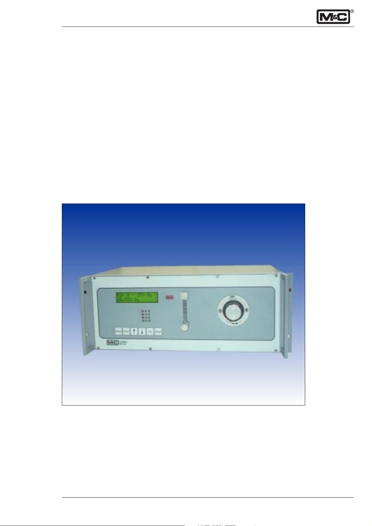
Microprocessor controlled oxygen analyser PMA
Version PMA100 (V1.52)
®
9-3.12-ME M&C Products Analysentechnik GmbH
Page 2

Table of content
1. Electrical standards 3
2. Important safety informations 3
3. Warranty 3
4. Used terms and signal indication 4
5. Introduction 4
5.1 Analyser model ............................................................................................................................ 4
5.2 Patent references ..........................................................................................................................4
5.3 Serial number ...............................................................................................................................4
5.4 Power supply ...............................................................................................................................4
5.5 Mounting system .......................................................................................................................... 4
6. Application 5
7. Description 5
7.1 Measuring principle ......................................................................................................................5
7.2 Flow diagram ................................................................................................................................6
7.3 Dimensions and weight ................................................................................................................7
7.4 Front panel .................................................................................................................................... 7
7.5 Technical data............................................................................................................................... 8
8. Supply connections 9
8.1 Medium ........................................................................................................................................ 9
8.2 Electrical .......................................................................................................................................9
8.2.1 mA output ..................................................................................................................................10
8.2.2 In- and output contacts .............................................................................................................. 10
8.2.3 Connector for solenoid valves ...................................................................................................10
9. Receipt and storage 11
10. Installation 11
11. Starting up 11
12. Menu description 12
13. Calibration 27
13.1 Calibration ..................................................................................................................................27
13.2 Cross-sensitivity .......................................................................................................................... 27
14. Measuring 30
14.1 Automatically range switch ........................................................................................................30
14.2 Expanded measuring range........................................................................................................ 30
15. Function of in- and output contacts and alarms 31
16. Closing down 32
17. Maintenance and repair 33
18. Trouble shooting 34
19. Spare part list 35
20. Appendix 35
- 2 -
This instruction manual does not claim completeness and is subject to technical modifications.
©5/1999 M&C Products Analysentechnik GmbH. Reproduction of this document or its content is not allowed without permission
from M&C.
PMA® is a registered trade mark.
5th edition: 02/2003
M&C Products Analysentechnik GmbH 9-3.12-ME
Page 3

- 3 -
1. Electrical standards
The electrical standard corresponds to the safety regula–
tions concerning the low-voltage recommendation 73/23
EWG in version 93/68 EWG and the recommendation of
electromagnetic compatibility 89/336 EWG in version
93/68 EWG.
We meet the following standards:
EN 61010 part 1 / EN 50081 part 1 / EN 50082 part 1
EN 55014 / EN 60555 part 2 & 3 / EN 60335 part 1
2. Important safety informations
Please note the following basic safety procedures when
using this equipment:
• Work on electrical equipment is only to be carried
out by trained specialists as per the regulations
currently in force.
• Attention must be paid to the requirements of IEC 364
(DIN VDE 0100) when setting high-power electrical units
with nominal voltages of up to 1000 V, together with the
associated standards and stipulations.
• Check the details on the type plate to ensure that
the equipment is connected up to the correct mains
voltage.
• Protection against touching dangerously high electrical
voltages.
Before opening the equipment, it must be switched and
hold no voltages. This also applies to any external
control circuits that are connected.
• The equipment is only to be set within the permitted
range of temperatures and pressures.
• Check that the location is weatherprotected. It should
not be subject to either direct rain or moisture.
• The equipment may not be operated in an area at
risk from explosion.
• Installation, maintenance, monitoring and any repairs
may only be done by authorised personnel with respect
to the relevant stipulations.
3. Warranty
If the equipment fails, please contact M&C directly or else
go through your M&C authorised dealer.
We offer a one year warranty as of the day of delivery as
per our normal terms and conditions of sale, and assuming
technically correct operation of the unit. Consumables are
hereby excluded. The terms of the warranty cover repair at
the factory at no cost or the replacement at no cost of the
equipment free ex user location. Reshipments must be
send in a sufficient and proper protective packaging.
9-3.12-ME M&C Products Analysentechnik GmbH
Page 4

4. Used terms and signal indication
- 4 -
SKILLED STAFF
These are persons with necessary qualification, who are
familiar with installation, use and maintenance of the
product.
The signals are used according to DIN 4844 and
EU Recommendation 91/C53/06.
These are important informations about the product or
parts of the instruction manual which require user’s
attention.
5. Introduction
5.1 Analyser model
The Oxygen analyser type PMA100 is produced by M&C
Products Analysentechnik in Ratingen, Germany.
5.2 Patent references
The M&C paramagnetic measuring cell is patented in
Europe and the USA under the following patent numbers:
• Germany Pat.-Nr. 36 33 750
• France Pat.-Nr. 87 13 608
• United Kingdom Pat.-Nr. 21 96 127
• The Netherlands Pat.-Nr. 188 2449
• USA Pat.-Nr. 4,807,463
5.3 Serial number
The type plate with the serial number is located at the back
panel of the analyser. Whenever you call M&C regarding
questions or orders for spares please give us the serial
number of your PMA.
5.4 Power supply
The power supply for the oxygen analyser PMA100 is 230V,
50Hz or 115V, 60Hz (‘a’ added to the Serial-No.). For detailed
information please look at the type plate of your analyser.
Variations of the power supply in a range of +10% to - 15%
have no influence on the function of the analyser.
5.5 Mounting system
The analyser is build in a 19“ housing, for rack or tablemounting.
M&C Products Analysentechnik GmbH 9-3.12-ME
Page 5
- 5 -
➡➡
6. Application
The transducer of the PMA100 works at a stable temperature of +55°C. Therefore the analyser is suitable for continuous measurements of oxygen concentrations in particlefree and dry sample gases.
Safe operation, reliability and minimized maintenance are
the characteristic of the PMA100.
The operation of the instrument is based upon the principle
of the magneto-dynamic cell which is the most accurate
and reliable cell for determining the oxygen content in gas
mixtures in a range of 0 to 100 Vol.-%.
The patented M&C measuring cell has been improved in
order to achieve stability, minimum drift of temperature and
extremely fast response time. Due to this fast response
time and the negligible cross-sensitivity from other gases
the PMA100 is applicable in a wide range of processes,
like:
• monitoring of flue gases,
• inerting installations,
• fermentation processes,
• process- and lab-measurements, etc.
7. Description
7.1 Measuring principle
The paramagnetic susceptibility of oxygen is significantly
greater than that of other common gases, and for this
reason the molecules of oxygen are attracted much more
strongly by a magnetic field than the molecules of other
gases. Most of the other gases are slightly diamagnetic,
e.g. the molecules are then repelled by a magnetic field.
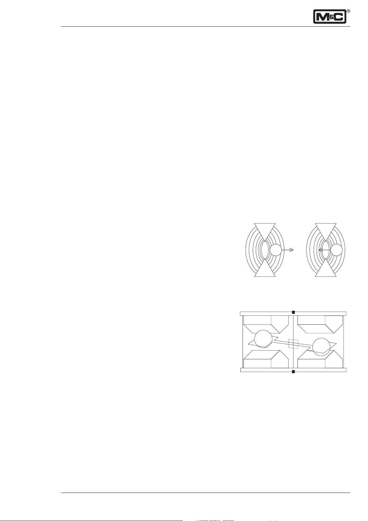
The principle of the magneto-dynamic cell is based upon
Faraday’s method of determining the magnetic susceptibility of gas. The cell consists of two nitrogen-filled quarts
spheres arranged in the form of a dumb bell. A single turn
of platinum wire is placed around the dumb bell which is
suspended in a symmetrical non-uniform magnetic field.
When the surrounding gas contains oxygen, the dumb bell
spheres are pushed out of the magnetic field by the change
in the field which is caused by the relatively strong paramagnetic oxygen. The torque acting on the dumb bell will
be proportional to the paramagnetism of the surrounding
gas and consequently it can be used as a measure of the
oxygen concentration.
N
N
2
S
Nitrogen=Diamagnetic Oxygen=Paramagnetic
Fig. 1: Magnetic susceptibility of gases
2
1
1 : Quarts sphere dumb bell
2 : Platinum wire
3 : Mirror
4 : Magnetic pole pieces
Fig. 2: The measuring cell in theory
3
N
S
4
O
2
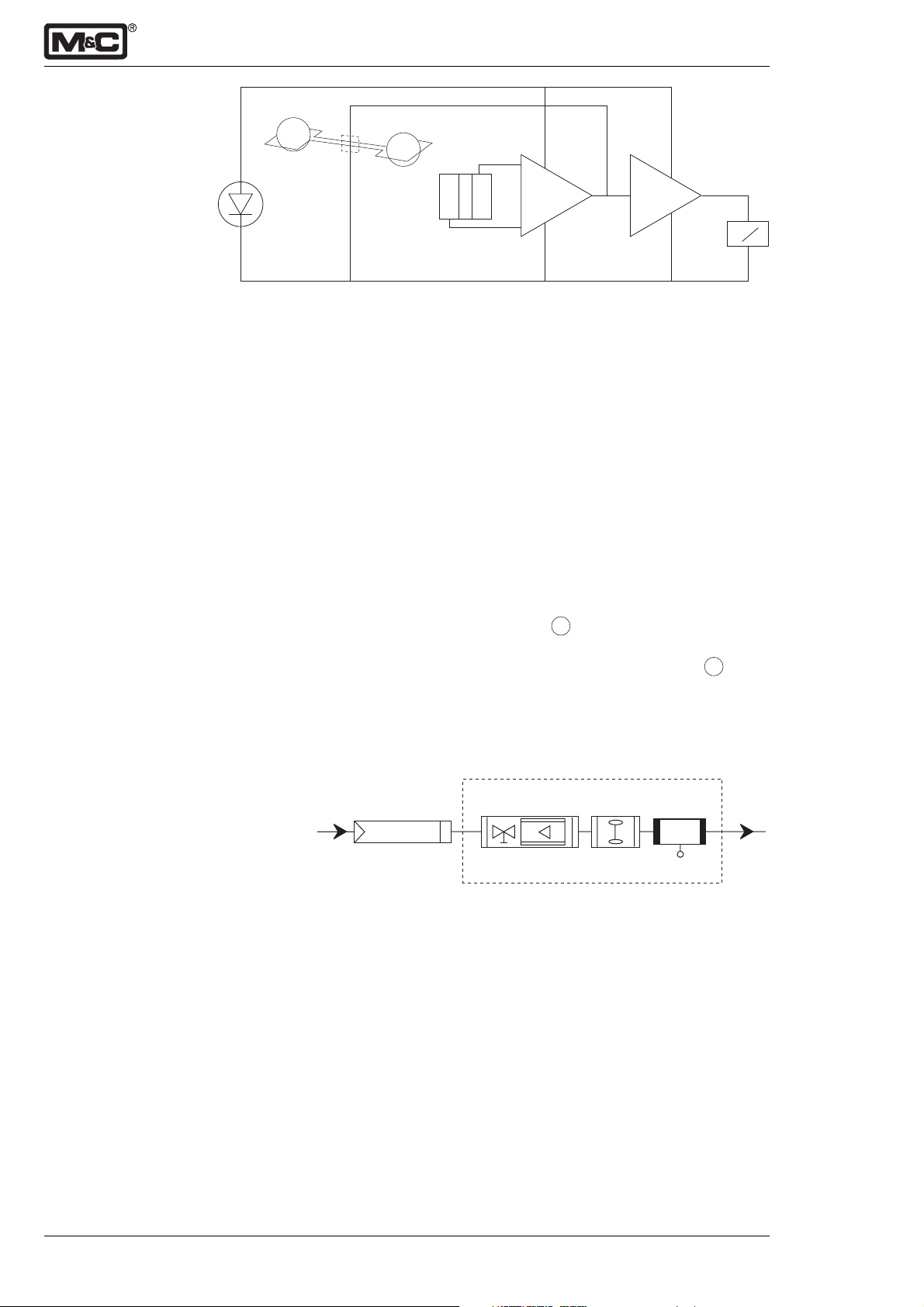
The distortion of the dumb bell is sensed by a light-beam
and projected on a mirror attached to the dumb bell whereof it is reflected to a pair of photo cells (Fig. 3). When both
photo cells are illuminated equally the output will be zero.
The output from the photo cells is connected to an amplifier,
which in turn is fed to the feedback coil of the measuring
cell. If the oxygen content of the gas sample changes,
9-3.12-ME M&C Products Analysentechnik GmbH
Page 6
- 6 -
1
1: Measuring cell
2: „LED“ light beam
3: Photo cell
4: Feed back amplifier
5: Output amplifier
6: Meter indication
Fig. 3: Principle of operation
➞
➞
23 54
the corresponding output of the amplifier, which is a current
and also proportional to the oxygen content, produces a
magnetic field in the feedback coil opposing the forces and
thereby causing the dumb bell to rotate.
Since the feedback current from the amplifier is proportional to the oxygen content of the gas sample, the output
signals produced by the amplifier will be accurate and
linear. The paramagnetic susceptibility of oxygen varies
inversely as the square of the absolute temperature. Therefore, a temperature sensitive element in contact with the
measuring cell assembly is included in the feedback
current circuit in order to provide compensation for
changes in analyser temperature.
7.2 Flow diagram
The flow can be adjusted in a range of 25 - 60Nl/h air at the
flowmeter with needle valve 2 built on the front panel of
the analyser.
The flow sensor at the outlet of the measuring cell 3 de–
tects the sample flow if it decreases under 25l/hr.
We recommend a conditioning system upstream the
analyser PMA100, e.g. consisting of a cooler and fine filter.
6
1: external filter
2: flowmeter with needle valve
3: patented M&C measuring cell PMA100
4: flow control
Fig. 4: Flow diagram of the analyser
1234
We like to inform you about suitable M&C equipment.
M&C Products Analysentechnik GmbH 9-3.12-ME
Page 7
- 7 -
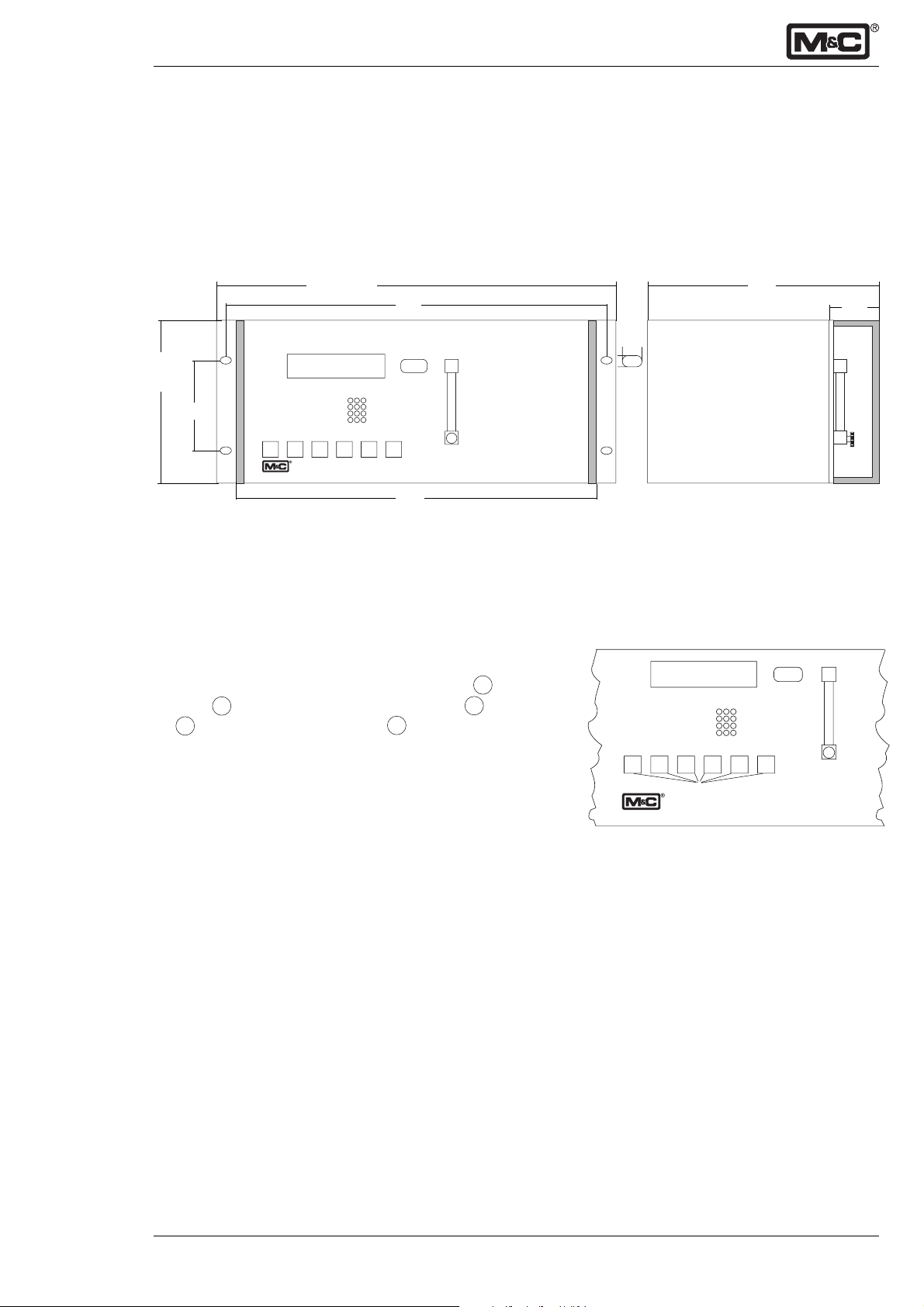
7.3 Dimensions and weight
The analyser is build in a 19” housing, also suitable for
table mounting. Fig. 5 shows the dimensions of the
PMA100. Please take additional 60mm fitting-depth into
consideration when installing the analyser.
The weight of the analyser is approx. 11 kg.
483
177
(4U)
(84HP)
20,9 V0l.% O
1010 mbar
102
⇑⇓
PMA100
465
2
Alarm
440
7.4 Front panel
The following figure shows the front panel of the oxygen
analyser PMA100.
You can see the double-lined LCD display 1 , the alarm
LED 2 , the flowmeter with needle valve 3 , status LEDs
4 and the six operating keys 5 .
The sample flow can be adjusted at the needle valve in a
range of 25-60Nl/hr.
The control panel refers to NAMUR standard and is
devided into:
• Select key
• Enter key
• Direction key
• Direction key
⇑⇑
⇑
⇑⇑
⇓⇓
⇓
⇓⇓
• Cal key
• Measuring key
(for more functional description see chapter 12)
341
50
10
7
Fig. 5: Dimensions of the PMA100
20,9 V0l.% O
1
1010 mbar
Selec Enter ⇑⇓Cal Meas
PMA100 O2-analyser
Fig. 6: Front panel with display, operating keys
and flowmeter
2
4
5
Alarm
2
3
9-3.12-ME M&C Products Analysentechnik GmbH
Page 8
- 8 -
7.5 Technical data
Part No. 03A3000(a): PMA100, power supply 230VAC, 50Hz, 115VAC, 60Hz
signal: 4-20mA; (a)=115V
Measuring ranges 4 linear measuring ranges free selectable, lowest span 1%,
basis parameterizing: 0-1; 0-10; 0-25; 0-100Vol.% O2 *; manual, automatic
or remote range control and range indication is possible
Indication, suitable in German, English and French 2 line, 16-sign. LCD-display, resolution 0,01Vol.%O2, continuous
O2-indication and read off O2-transducer temperature, mA-signal, measuring range, time, date, error/alarm message, process pressure
Output signals selection: isolated 0-20, 2-20, 4-20*, 4-20.5mA for the selected range,
max. load 500Ω;
interface RS232, AK communication protocol, bi-directional,
option: interface RS485
Relay outputs, free configurable 4 potential free relay contacts NO, contact rating max. 48VDC, 500mA, 15W
Binary outputs 24VDC, max. 400mA, controlling of 3 external valves for calibration
Binary inputs, free configurable potential free, 4 x 12 - 24VDC, max. 20mA or internal 24V
Flow alarm caloric conductibility sensor in the outlet of the cell
Status alarm for min. flow, transducer temp. < 50°C, processor error,
pressure sensor: LED-indication and potential free contact output,NO,
max. 48VDC, 500mA, 15W and mA output signal, f.e. 22mA
Alarm contact for underflow or exeeding of the measuring range, termination of the
calibration, external alarm, concentration alarm: LED-indication and
potential free contact output, NO, max. 48VDC, 500mA, 15W
Response time for 90%-FSD < 3sec at 60 NI/hr air
Accuracy after calibration deviation ± 1% of 2-100% span, ±2% of 1% span
Reproducibility deviation < 1% of span
Influence of ambient temperature no influence up to 50°C
Influence of barometric or process pressure the oxygen reading varies in direct proportion to the baromatric or process
pressure variation
option: integrated process pressure compensation for the range 0,6 to
1,6bar abs., part no.: 03A9300
Influence of sample gas flow variation in gas flow between 0 and 60 Nl/hr air will cause a difference in
reading of < 0,1Vol.%O
2
Sample gas
- inlet pressure 0,01 up to 0,5bar g (PMA100 requires positive pressure for adequate flow
rate, no pump inside)
- outlet pressure outlet of analyser should discharge freely into atmosphere, or see option:
pressure compensation
- flow rate 25 - 60 Nl/hr air
- temperature -10°C up to +50°C dry gas
O2-transducer temperature fixed at +55°C
Ambient temperature -10°C up to +50°C
Storage temperature -20°C up to +60°C, rel. humidity 0-90% RH
Power supply internal power unit for 230VAC or 115VAC available, (a) +/-10%, 40-60 Hz, 35VA
Electrical connections mains supply: 3-pol. chassis plug with 2m cable; signals: 4 x Sub-D plug
Materials in contact with sample gas platinum, epoxy resin, glass, FPM, stainless steel 316, PTFE, PVDF
Sample gas connection 1/8“ NPT internal thread*, option with tube connector DN 4/6 PVDF
available part no.: 05V1045
Protection / Electrical standard IP40 (EN60529) / EN61010
Housing/ 19“ rack mounting with front handles
Front colour grey RAL 7032
Dimensions/ width: 84HP; hight: 4U; depth: 350mm + approx. 60mm installation space
Weight approx. 11 kg
supply voltage
DC
* standard/basis execution
M&C Products Analysentechnik GmbH 9-3.12-ME
Page 9
- 9 -
8. Supply connections
8.1 Medium
Note!
The oxygen analyser PMA100 is suitable for continuous
measurements of oxygen concentrations in particle-free
and dry sample gases. Therefore it is recommended to use
a gas conditioning system upstream the analyser, e.g.
equipped with a cooler and a particle filter.
We like to inform you about suitable M&C equipment.
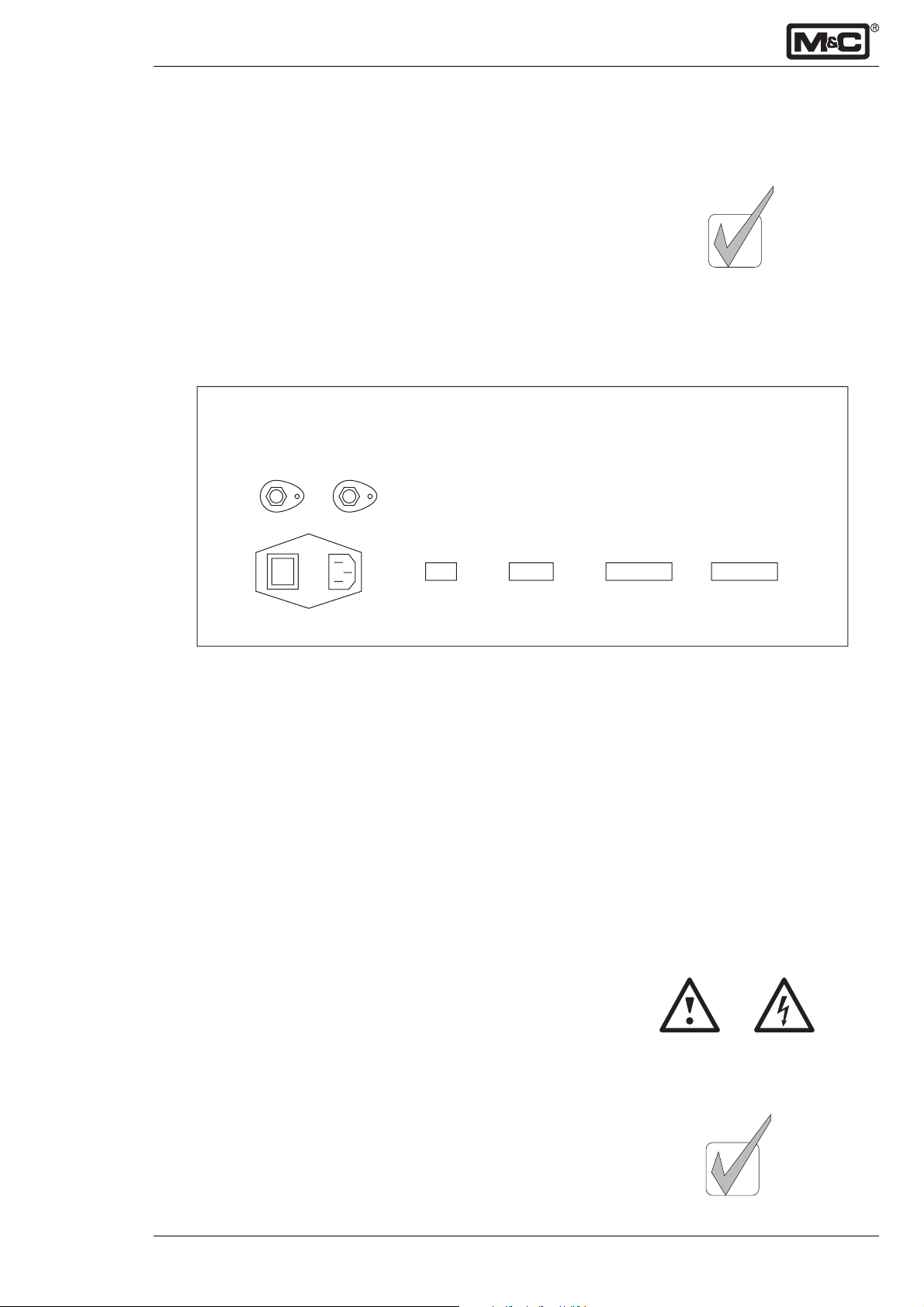
The following diagram shows the connections on the back
panel of the PMA100.
Sample in Sample out
Before opening the assembly cover
disconnect the electrical supply!
X1 X2 X3 X4 X5
Power in
Patented measuring cell
USA patent number 4807463
For connection of the sample gas in- and outlet use 1/8”
NPT male fittings.
We like to inform you about our range of tube and pipe
connectors.
8.2 Electrical
The analyser PMA100 is equipped with an internal power
switch. The 2m cable with 3-pole plug at the end is part of
the standard supply.
False supply voltage can damage the equipment. When
connecting the equipment, please ensure that the supply
voltage is identical with the information provided on the
model type plate!
Fig. 7: Connections on the back panel of the
PMA100
Note!
For the erection of power installations with rated voltages
up to 1000V, the requirements of VDE 0100 and relevant
standards and specifications must be observed!
The main circuit must be equipped with a fuse corresponding to the nominal current (over current protection); for
electrical details see technical data (chapter 7.5).
9-3.12-ME M&C Products Analysentechnik GmbH
Page 10

mA +
mA +
mA +
mA +
mA -
Fig. 8: 15-pole Sub-D socket X3
Out 4 MC
Out 3 NO
Out 2 MC
Out 1 NO
Alarm MC
Status MC
Out +24V
IN 1,2,4; GND
IN 3 (+24V)
In 1 (+24V)
In 4 (+24V)
1
9
10
11
12
13
14
15
14
15
16
17
18
19
20
21
22
23
24
25
mA -
mA -
mA -
mA -
mA -
mA -
mA -
Out 4 NO
Out 3 MC
Out 2 NO
Out 1 MC
Status NO
Out 0V
IN 3; GND
Alarm NO
In 2 (+24V)
2
3
4
5
6
7
8
1
2
3
4
5
6
7
8
9
10
11
12
13
- 10 -
8.2.1 mA output
The mA output is available on the back panel of the
PMA100 (see fig.8) at the 15-pole Sub-D socket X3. The
following figure shows the configuration of the terminal.
For multichannel version the outputs are arranged as
follows:
1 channel 1,
2 channel 2,
3 channel 3,
4 channel 4.
The menu-driven handling of the mA outputs is described in
chapter 12.
8.2.2 In- and output contacts
Fig. 9 shows the configuration of the terminal X4. The
following connections are available at the 25-pole Sub-D
plug:
• four binary inputs, In1 to In4, with 12V - 24V, max. 20mA,
• four binary output contacts, Out1 to Out4, with 48V,
max. 500mA,
• one alarm contact, Alarm MC and Alarm NO, with 48V,
max. 500mA,
• one status contact output, Status MC and Status NO,
with 48V, max. 500mA. and
• one supply power contact, Out +24V and Out 0V, with
24V, max. 100mA.
Fig. 9: 25-pole Sub-D plug X4
24V
+0V Y1
+0V Y2
24V
+0V Y3
Option
24V
Option
Option
24V
Option
Option
24V
Fig. 10: 25-pole Sub-D socket X5
1
2
3
4
5
6
7
8
9
10
11
12
13
14
15
16
17
18
19
20
21
22
23
24
25
Option
Option
24V
Option
Option
24V
Option
Option
24V
Option
Option
24V
The menu-driven handling of the in- and outputs is
described in chapter 12.
8.2.3 Connector for solenoid valves
Fig. 10 shows the 25-pole Sub-D socket X5 with the supply
power to control three external solenoid valves. At the moment
three conections are available:
• pin 2 connection for the zero gas solenoid valve, 24V,
max. 400mA,
• pin 3 connection for the span gas solenoid valve, 24V,
max. 400mA, and
• pin 5 connection for the sample gas solenoid valve, 24V,
max. 400mA.
The menu-driven handling of the in- and outputs is
described in chapter 12.
M&C Products Analysentechnik GmbH 9-3.12-ME
Page 11
- 11 -
9. Receipt and storage
The PMA100 is completely pre-installed and normally delivered in one packaging unit.
• Please take the analyser and possible special accessories carefully out of the packaging material immediately after arrival, and compare the goods with the items
listed on the delivery note;
• Check the goods for any damage caused during delivery
and, if necessary, notify your transport insurance company without delay of any damage discovered.
Note!
The oxygen analyser PMA100 must be stored in a wheather-protected frost-free area!
10.Installation
The PMA100 is built in a 19“ housing, which is also suitable
for table mounting.
Accurate and proper installation of the PMA100 analyser
will not only minimize instrument breakdown, but it will also
result in reliable operation of the analyser.
The operator must be satisfied that the analyser installation
and positioning is safe for extremes of conditions which
could occur in the operating environment of the analyser.
Choose installation sites which are reasonable free from
vibration sources, and are not subjected to large temperature fluctuations outside the analyser specifications.
Without any precautions avoid any back pressure different
from barometric pressure at the gas outlet of the analyser.
Note that the PMA100 analyser is only suitable for
measuring of non-hazardous gas mixtures in non-hazardous areas!
11.Starting up
Before using the equipment for the first time, check that the
safety measures specific to the installation and process are
complied with.
Before connecting the analyser to the mains, compare
the mains voltage with the information on the type plate
of the analyser.
Note!
The working temperature of the analyser is 55°C. After
starting, the analyser warms up. The current temperature is
displayed.
During the warm-up time the menu of the analyser is locked
for use.
9-3.12-ME M&C Products Analysentechnik GmbH
Page 12

12.Menu description
12.1 Table of content
• Overview menu-drive and Overview operating keys ....................................................................................... 13
12.2 Warming up ....................................................................................................................................................... 14
12.3 Alarm log-book ................................................................................................................................................. 14
12.4 Parameterising level 1 ........................................................................................................................................ 15
12.4.1 Language ........................................................................................................................................................... 15
12.4.2 Select range ....................................................................................................................................................... 15
12.4.3 Set range ............................................................................................................................................................ 15
12.4.4 Set autorange hysteresis .................................................................................................................................... 15
12.4.5 Current output ................................................................................................................................................... 15
12.4.6 Status error mA .................................................................................................................................................. 16
12.4.7 Set date/time ..................................................................................................................................................... 16
12.4.8 Relay configuration ............................................................................................................................................ 16
12.4.9 Input configuration ............................................................................................................................................ 17
12.4.10 Average ............................................................................................................................................................. 17
12.4.11 Concentration alarm .......................................................................................................................................... 18
12.5 Parameterising level 2 ........................................................................................................................................ 19
12.5.1 Step into the menu ............................................................................................................................................ 19
12.5.2 LCD contrast ...................................................................................................................................................... 19
12.5.3 Calibration method ........................................................................................................................................... 19
12.5.4 Calibration interval ............................................................................................................................................. 19
12.5.5 Current signal with calibration ........................................................................................................................... 20
12.5.6 Calibration time ................................................................................................................................................. 20
12.5.7 Measuring time .................................................................................................................................................. 20
12.5.8 Pressure compensation ..................................................................................................................................... 20
12.6 Calibration of the pressure sensor ..................................................................................................................... 20
• Current pressure ................................................................................................................................................ 21
• Data output ........................................................................................................................................................ 21
• Memory clear .................................................................................................................................................... 21
12.7 Interface communication and passwords ........................................................................................................ 21
12.7.1 Baud rate (correlation with the ser. interface RS232) ........................................................................................ 21
12.7.2 Communication channel (communication with the ser. interface RS232/485) ................................................ 21
12.7.3 STX and ETX character ...................................................................................................................................... 22
12.7.4 Change password level 1 .................................................................................................................................. 22
12.7.5 Change password level 2 .................................................................................................................................. 22
12.8.1 Inquiry of the transducer channel ..................................................................................................................... 22
12.8.2 Read NV-Memory Editor ................................................................................................................................... 22
12.8.3 Device mode ..................................................................................................................................................... 23
12.8.4 Select channel ................................................................................................................................................... 23
12.8.5 Arrangement of the mA-outputs ....................................................................................................................... 23
12.8.6 Set active valve .................................................................................................................................................. 23
12.8 Zero- and span calibration ................................................................................................................................ 24
12.8.1 Zero gas concentration ..................................................................................................................................... 24
12.8.2 Span gas concentration ..................................................................................................................................... 24
12.8.3 Calibration ......................................................................................................................................................... 24
• Manual calibration ............................................................................................................................................. 24
• Manual calibration offset ................................................................................................................................... 25
• Autocalibration offset ....................................................................................................................................... 25
• Autocalibration ................................................................................................................................................. 25
12.8.4 Deviation from calibration ................................................................................................................................. 26
12.8.5 Calibration log-book ......................................................................................................................................... 26
- 12 -
M&C Products Analysentechnik GmbH 9-3.12-ME
Page 13

- 13 -
Overview menu-drive Overview operating keys
Display
Status
Alarm log-book
Entry code
Code 1
Language
Code 2
LCD contrast
Meas
Cal
Select
Enter
↑↓
Read only
see
code1
• Startup of measuring menu
• Function: to leave the actual menu
structure to the measuring display
• Startup of calibration
• Selection of menu points
• Selection of changeable positions
• Jump into submenu
• Confirmation of input
• Selection of submenu points if shown on
the display
Cal
Zerogas
concentration
Measuring
range
Current output
Date/Time
Relayconfiguration
Relay NC/NO
Keep alarm
yes/no
Inputconfiguration
Average
Concentrationalarm
Calibrationmethod
Calibrationpressure sensor
Current
pressure
Data output
Memory clear
Interface
communication
Password
NV-Memory
Device mode
Spangas
concentration
Calibration
Deviation from
calibration
Calibration
log-book
Alarm
range
Alarm signal
9-3.12-ME M&C Products Analysentechnik GmbH
Page 14

MC Para O
TM M&C Products
2
V 1.52
- 14 -
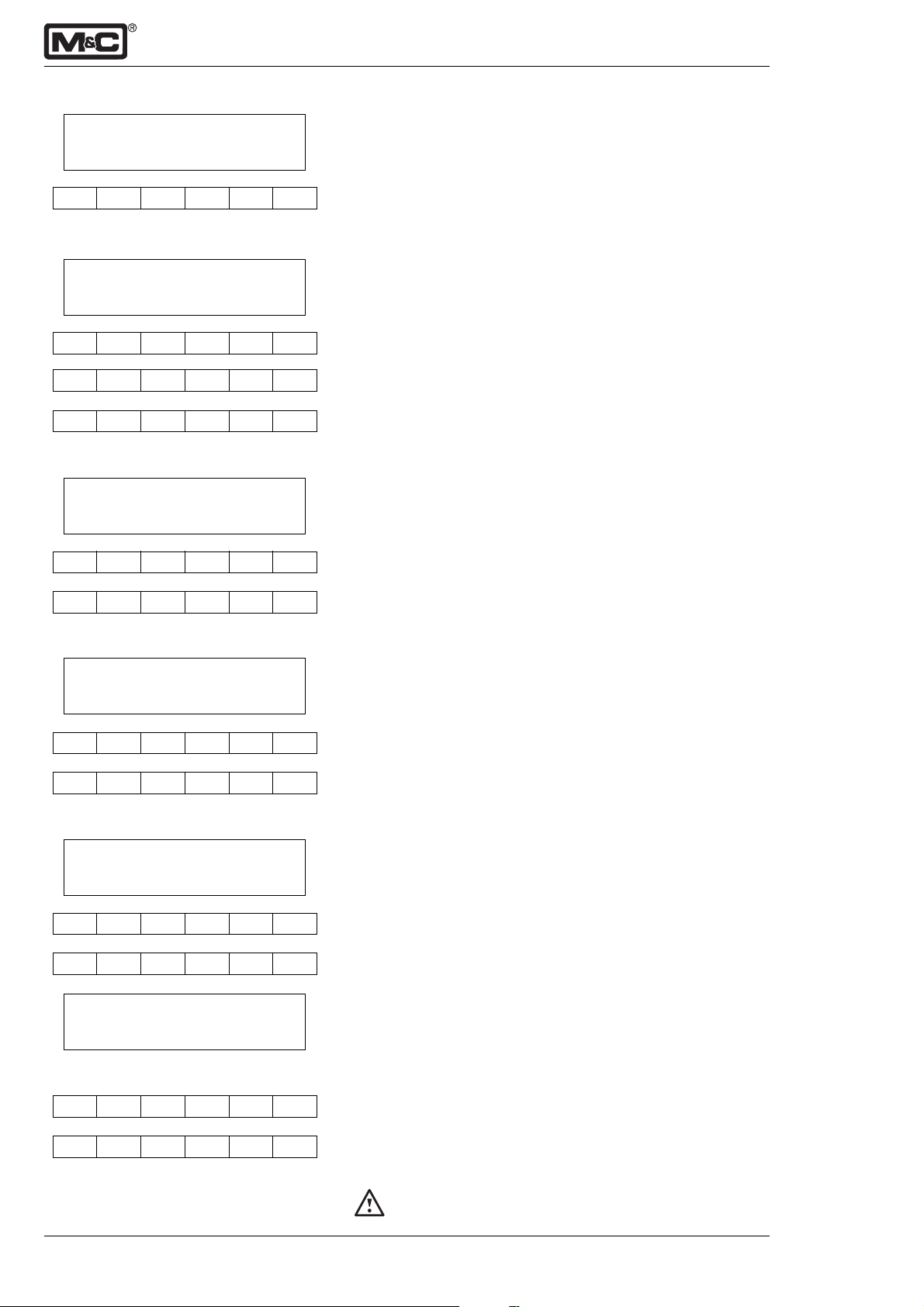
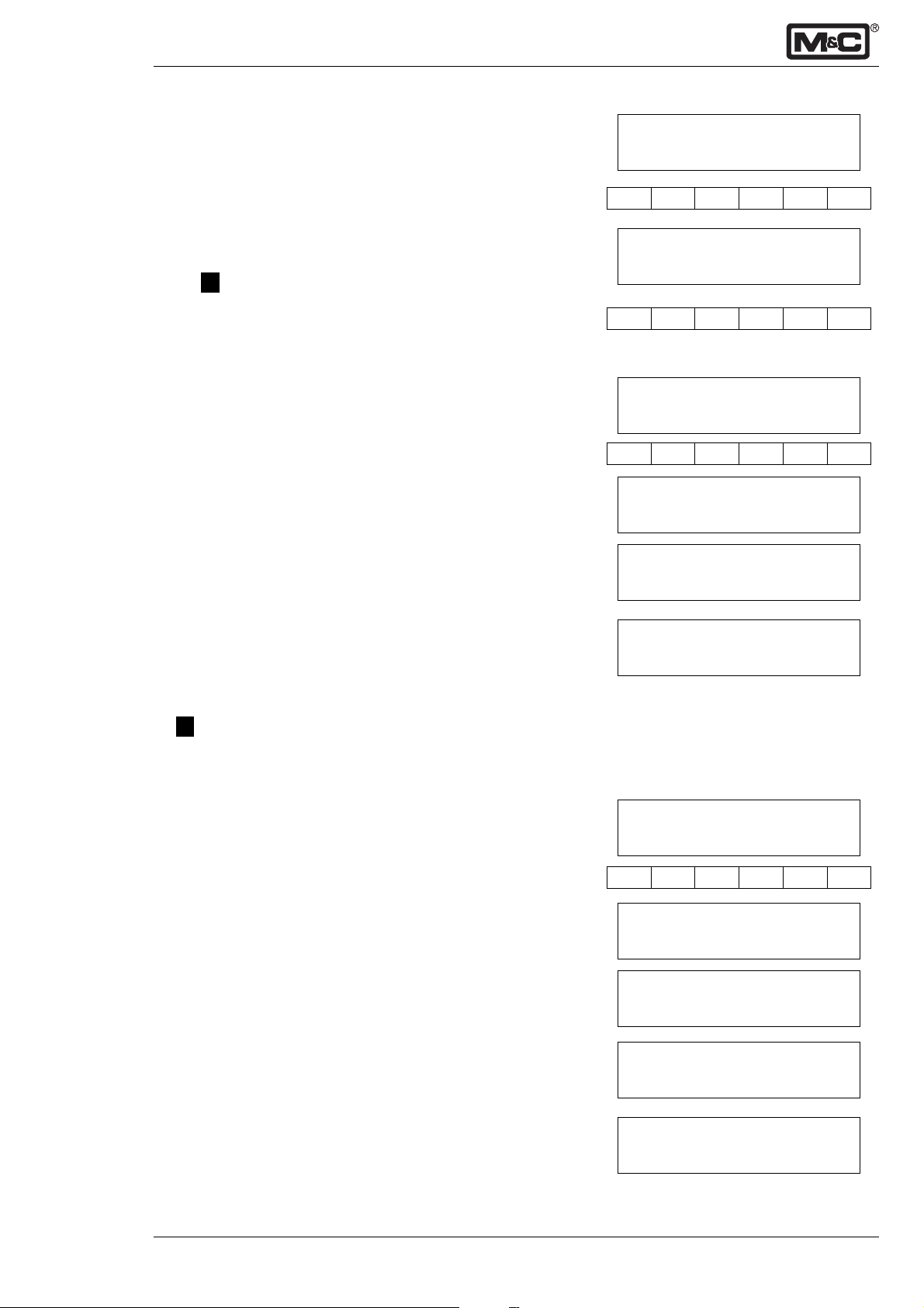
12.2 Warming up
After switching on the analyser type PMA100, the warmingup begins.
The following display appears for approximately 20 seconds:
• M&C logo
• current O2-concentration
• Software-version implemented in the PMA100
• and the trademark.
press: 1005 mbar
press: 1005 mbar
heating 22.5°C
Select
alarm log-book
Select
After further 20 seconds the display changes. Via the Direction keys ⇑⇓ the following current values can be indicated:
• measuring range,
• temperatur of the transducer,
⇑⇑
⇓⇓
⇑
⇓
⇑⇑
⇓⇓
• pressure in the measuring-cell,
• date/time,
• current output.
The second line displays the heating procedure.
The warming-up is finished by reaching a temperature of
54°C. The display shows either the current value (see
above) or an error message. The second line of the display
presents the current oxygen concentration (for multi-channel
version the concentration of the respective channel).
The Select key leads to the next menu point.
12.3 Alarm log-book
The starting time and the 9 last alarms are stored. The
Direction keys ⇑⇓ can be used going through the alarm logbook. The current alarm message is shown on the display
like E ....
The Select key leads to the entry of the access code.
enter to config.
Code: 0000
Enter
enter to config.
Code: 0000
Select
Enter
enter to config.
Level 1
Select
The Enter key opens the access code menu for the first,
second respectively read only level.
The first changeable position is underlined. With the Direction keys ⇑⇓ the value of the position can be changed in
between 0 and 9. A jump to the next position happens via
the Select key. The entry of the complete code has to be
confirmed by the Enter key and is shown in the second line
of the display.
The codes are preadjusted at the factory:
Code:0010 level 1
⇑⇑
⇓⇓
⇑
⇓
⇑⇑
⇓⇓
Code:1000 level 2
Code:0000 read only-level;
The read only-level allows a passage through all menu
points of level 1 via the Select key. In this level parameters
can not be changed.
The Select key leads to level 1 - measuring parameters,
⇑⇑
⇓⇓
⇑
⇓
⇑⇑
⇓⇓
relay-, input and output configuration.
M&C Products Analysentechnik GmbH 9-3.12-ME
Page 15

- 15 -
12.4 Parameterising level 1
12.4.1 Language
The following languages are selectable by the Direction
keys ⇑⇓ :
• English,
• German,
• French.
Enter confirms the choice.
The Select key leads to the next menu point.
12.4.2 Select range
After the entry of the code for level 1 the display opens to
the select range menu. Four variable ranges and the autorange are available. The functions can be selected by the
Direction keys ⇑⇓ . With the autorange always the favourable range is used.
In combination with the autorange function, unused measuring
ranges are requested to be set to 0 (see 12.4.3).
The Select key leads to the next menu point.
12.4.3 Set range
The desired ranges 1 to 4 or the autorange are selected by
the Direction keys ⇑⇓ . The display is opened for changes
by the Enter key. The first changeable position is
underlined and can be changed operating the Direction
keys ⇑⇓ . A jump to the next position happens via the
Select key. The entry of the complete measuring range has
to be confirmed by the Enter key.
language
English
Enter
Select
select range 1
r1(...4), autorange
Enter
Select Enter
Select
set range 1
xx%O2 - xxx,x%O
Enter
Select Enter
↑
↑
⇑⇑
⇓⇓
⇑
⇓
⇑⇑
⇓⇓
↑
↑
⇑⇑
⇓⇓
⇑
⇓
⇑⇑
⇓⇓
2
⇑⇑
⇓⇓
⇑
⇓
⇑⇑
⇓⇓
The Select key leads to the next menu point.
12.4.4 Set autorange hysteresis
This adjustment is important using the autorange function.
The %-value is related to the smallest span of the relevant
switching ranges and determines the interval switching into
the next lower range (see 14.1).
The entry starts with the Enter key. The first changeable
position is underlined and can be changed operating the
Direction keys ⇑⇓. A jump to the next position happens via
the Select key.
The entry has to be confirmed by the Enter key, and the
Select key leads to the next menu point.
12.4.5 Current output
Two adjustments are possible:
1. fixed output signal and
2. output signal with range of tolerance showing the
underflow respectively exceeding of the signal range.
The following ranges are preseted:
• 0 - 20mA • 0 - 20mA + 0,45mA
• 2 - 20mA • 2 - 20mA ± 0,45mA
• 4 - 20mA • 4 - 20mA ± 0,45mA
Select
set hyst. autor.
xx.xx%
Enter
Select Enter
Select
current output
0-20mA, 2-20mA, ...
⇑⇑
⇓⇓
⇑
⇓
⇑⇑
⇓⇓
↑
↑
⇑⇑
⇓⇓
⇑
⇓
⇑⇑
⇓⇓
9-3.12-ME M&C Products Analysentechnik GmbH
Page 16

- 16 -
Enter
Select
status error mA
no, 0mA, 2mA, 20,5mA, ...
⇑⇑
⇑
⇑⇑
Enter
Select
set date/time
MM-DD-YY hh:mm
Enter
Select
⇑⇑
⇑
⇑⇑
A selection is done by the Direction keys ⇑⇓ and confirmed
by the Enter key.
The Select key leads to the next menu point.
12.4.6 Status error mA
↑
↑
Using a permanent current output signal, status errors can
be identified. The output signal is selected via the Direction
keys ⇑⇓ and confirmed by the Enter key.
⇓⇓
⇓
⇓⇓
The following output signals are available:
• no output signal
• 0 mA • 2 mA
• 20,5 mA • 21 mA
• 22 mA • 22,5 mA
•23mA • 24mA
The Select key leads to the next menu point.
12.4.7 Set date/time
The Enter key enables the entry of the date/time values:
first month, day and year, then hour and minute.
The first changeable position is underlined and can be
changed operating the Direction keys ⇑⇓ .
⇓⇓
⇓
⇓⇓
A jump to the next position happens via the Select key.
The entry has to be confirmed by the Enter key, and
operating once more the Select key leads to the next menu
point.
relay config.
relay 1
Enter
relay config.
R1: span1...4,conc. alarm1...4
Enter
Select
relay nc = 1
1:0 2:0 3:0 4:0
Enter
Select Enter
Select
⇑⇑
⇑
⇑⇑
⇑⇑
⇑
⇑⇑
⇑⇑
⇑
⇑⇑
12.4.8 Relay configuration
↑
↑
This menu point determines the function of maximum four
relays, R1 to R4 (see 7.5 technical data). A selection of the
relays is done by the Direction keys ⇑⇓ .
⇓⇓
⇓
⇓⇓
The Enter key opens the Entry and the Direction keys ⇑⇓
select the desired function:
• allocation of the measuring ranges 1 to 4
• measuring span error
• concentration alarm (1 to 4)
• calibration
⇓⇓
⇓
⇓⇓
• flow alarm
• external alarm (see 12.4.9).
The Enter key confirms the selection.
The Select key leads to the next menu point.
This menu point selects whether the relay functions as:
0 normally open contact
1 normally closed contact
The entry starts with the Enter key. The first changeable
⇓⇓
⇓
⇓⇓
position is underlined and can be changed operating the
Direction keys ⇑⇓ . A jump to the next position happens via
the Select key.
The entry has to be confirmed by the Enter key, and the
Select key leads to the next menu point.
M&C Products Analysentechnik GmbH 9-3.12-ME
Page 17

- 17 -
An alarm situation can be kept. If yes, one input must be
configured as a reset (see 12.4.9).
The entry starts with the Enter key. The first changeable
position is underlined and can be changed operating the
Direction keys ⇑⇓ . A jump to the next position happens via
the Select key.
The entry has to be confirmed by the Enter key, and the
Select key leads to the next menu point.
12.4.9 Input configuration
Inputs 1 to 4 are selected by the Direction keys ⇑⇓ (see 7.5).
The Enter key opens the entry. The Direction keys ⇑⇓ select
one of the following input functions:
• external alarm (passing through an incoming signal),
• set span 1 to 4,
• autocalibration offset,
• autocalibration,
• alarm reset,
resets all alarms, which are setted to ‘keep alarm=1’ in
the previous menu point. The signal for the reset function
must be an impulse.
keep alarm = 1
1:0 2:0 3:0 4:0
Enter
Select Enter
Select
input config.
input 1...4
Enter
input config.
external alarm
⇑⇑
⇓⇓
⇑
⇓
⇑⇑
⇓⇓
↑
↑
⇑⇑
⇓⇓
⇑
⇓
⇑⇑
⇓⇓
The choice has to be confirmed via the Enter key.
The Select key leads to the next menu point.
12.4.10Average
This menu point opens the possibility to determine an
average value over a maximum measuring time of 100
seconds. This average value is displayed. The desired
value can be selected via the Direction keys ⇑⇓.
The Enter key operates the confirmation and the Select
key leads to the next menu point.
Enter
Select
average
no, 1, ..., 100 seconds
Enter
Select
⇑⇑
⇓⇓
⇑
⇓
⇑⇑
⇓⇓
↑
↑
⇑⇑
⇓⇓
⇑
⇓
⇑⇑
⇓⇓
9-3.12-ME M&C Products Analysentechnik GmbH
Page 18

conc. alarm 1...4
[< or >] xx.xx%
Enter
Select
Select
conc. alarm 1...4
alarm contact/ ...
Select Enter
Select
- 18 -
12.4.11Concentration alarm
↑
↑
The user is able to set maximum four threshold values in
Vol.-% O2 as a minimum or maximum alarm limit. The values
1 to 4 are selected by the Direction keys ⇑⇓ . The Enter key
opens the entry. The cursor jumps to the first changeable
⇑⇑
⇓⇓
⇑
⇓
⇑⇑
⇓⇓
position, the <-/>-sign for minimum respectively maximum
limit. A selection is operated via the Direction keys ⇑⇓ . A
⇑⇑
⇓⇓
⇑
⇓
⇑⇑
⇓⇓
jump to the next position happens via the Select key. The
entry has to be confirmed by the Enter key.
The Select key leads to the next menu point.
• Display concentration alarm
↑
↑
The following menu point determines whether a concentration alarm is displayed as:
• alarm contact,
• status contact, or
⇑⇑
⇓⇓
⇑
⇓
⇑⇑
⇓⇓
• no.
A selection happens via the Direction keys ⇑⇓, and is
confirmed by the Enter key. If ‘no’ is selected, the alarm
signal can be used as a relay control output (see 12.4.8).
The Select key leads to the next threshold value.
After reaching the 4th value the Select key leads to the next
menu point.
alarm hysteresis
xx.xx%
Enter
alarm hysteresis
xx.xx%
Select
Select Enter
set beep
off/on
Enter › fl
Select
• Alarm range
The alarm range is determined by a percentile of the alarm
threshold value.
The Enter key opens the menu for the entry of above
mentioned value. The first changeable position is under–
⇑⇑
⇓⇓
⇑
⇓
⇑⇑
⇓⇓
lined and can be changed operating the Direction keys ⇑⇓ .
A jump to the next position happens via the Select key.
The entry has to be confirmed by the Enter key, and operating once more the Select key leads to the next menu point.
• Set alarm beep
↑
↑
The optical alarm display can be supported by a beep
alarm signal. The function beep on or off is selected via the
Direction keys ⇑⇓ . The Enter key confirms the choice.
Operating the Select key leads to the beginning of the
menu.
Anytime you want to start up the menu anew press the
Meas
M&C Products Analysentechnik GmbH 9-3.12-ME
Measuring key.
Page 19

- 19 -
12.5 Parameterising level 2
12.5.1 Step into the menu
System parameters can be changed in level 2. Operating
the MEAS key leads back to the configuration level.
Operating two times the Select key leads from the measuring menu to the entry of the access code (see 12.2).
Select
Enter to config.
Code: 0000
The Enter key opens the menu. The first changeable
position is underlined and can be changed via the Direction
keys ⇑⇓ . Operating the Select key jumps to the next
position. The entry of the complete code (1000 preadjusted
at the factory) has to be confirmed by the Enter key.
The Select key leads to the next menu point.
12.5.2 LCD contrast
The display background gets darker with increasing
ambient temperatures. To get a better contrast, the letters
on the display can be changed to more light colour. The
Enter key opens the entry display. The desired contrast is
set by the Direction keys ⇑⇓ inbetween a range of 0 to 7
(light coloured letters). The Enter key confirms the entry.
The Select key leads to the next menu point.
12.5.3 Calibration method
It is possible to choose or enable the calibration methods
by the Direction keys ⇑⇓:
• manual calibration,
• manual calibration offset,
• autocalibration offset,
• autocalibration.
With Enter you step into the calibration menu.
The desired function is set by the Direction keys ⇑⇓ , and
confirmed by the Enter key.
Enter
Enter to config.
Code: 0000
Select Enter
Select
LCD-contrast
(0...7):0
Enter
Enter
Select
cal. menu point
manual cal.
Select Enter
manual cal.
yes/no
Enter
⇑⇑
⇓⇓
⇑
⇓
⇑⇑
⇓⇓
⇑⇑
⇓⇓
⇑
⇓
⇑⇑
⇓⇓
↑
↑
⇑⇑
⇓⇓
⇑
⇓
⇑⇑
⇓⇓
Select leads to the next menu point.
Select
12.5.4 Calibration interval
This menu point determines the time steps (in hours) using
cal. interval
the autocalibration function (see 13.).
t in hours: 001
Enter opens the display, and the data input is operated by
⇑⇑
the Direction keys ⇑⇓ .
Enter
cal. interval
001
⇓⇓
⇑
⇓
⇑⇑
⇓⇓
↑
↑
The Enter key confirms the entry, and the Select key leads
to the next menu point.
9-3.12-ME M&C Products Analysentechnik GmbH
Select Enter
Page 20
cal. current
off/on
- 20 -
12.5.5 Current signal with calibration
During the calibration a mA-signal can be put out as:
off mA-signal of the last measuring value
on current signal of the respective calibration gas
Select
cal. time [s]
fill: 090 cal: 095
Enter
Select
Select
meas. time [s]
fill: 000 meas: 02
Enter
Select Enter
press compens.
on/off
Enter
⇑⇑
⇑
⇑⇑
⇑⇑
⇑
⇑⇑
⇑⇑
⇑
⇑⇑
The Select key leads to the next menu point.
12.5.6 Calibration time
This menu point sets the backflush respectively calibration
time in case of the autocalibration function. The entry of the
time steps happens in seconds and counts backwards
from the final value (see 13.3). Enter opens the display, and
the data input is operated by the Direction keys ⇑⇓ .
⇓⇓
⇓
⇓⇓
The Enter key confirms the entry, and the Select key leads
to the next menu point.
12.5.7 Measuring time
This menu point sets the backflush respectively measuring
time in case of the measuring point switch function. Enter
opens the display, and the data input is operated by the
Direction keys ⇑⇓ .
⇓⇓
⇓
⇓⇓
The Enter key confirmsthe entry, and the Select key leads
to the next menu point.
12.5.8 Pressure compensation
↑
↑
A pressure compensation is implemented in the oxygen
analyser type PMA100. The compensation is switched on
or off via the Direction keys ⇑⇓ , and confirmed by the
Enter key.
⇓⇓
⇓
⇓⇓
Select
cal. p.-sensor
. . . %O
20.21 %O
20.21 %O
Select
2
Enter
Enter
Enter
The Select key leads to the next menu point.
12.6 Calibration of the pressure sensor
Three steps are necessary to calibrate the pressure sensor:
1. Air is given to the analyser under normal ambient pres-
P: . . .
sure. Operating the Enter key starts the calibration procedure. The cursor jumps to the first changeable point. If ne-
⇑⇑
⇓⇓
⇑
⇓
⇑⇑
⇓⇓
cessary the value for the current pressure can be corrected
operating the Direction keys ⇑⇓ . After operating the Enter
key the display changes. The first line shows the O2-concen–
tration and the pressure on the low level.
2
2
P: 1022
P: 400
2. The pressure has to be increased by minimum 300 mbar
(max. pressure 0,6bar), throttling the flow at the sample
outlet of the analyser. The second line on the display shows
the variable pressure.
3. After compensation of the two O2- readings (first and
second line) the calibration is confirmed operating the
Enter key.
The Select key leads to the next menu point.
Zero and span calibration have to be carried out after
calibration of the pressure sensor.
M&C Products Analysentechnik GmbH 9-3.12-ME
Page 21
- 21 -
• Current pressure
The Enter key opens the display to change the value for
the current pressure. The corrected value has no influence
on the O2- reading. The modified pressure value is con–
firmed by the Enter key.
current pressure
.....mbar
Enter
The Select key leads to the next menu point.
• Data output
The measuring data can be handed as follows:
• no data output,
• stored on the internal RAM,
• send to a Printer, or
• stored on RAM and send to a Printer.
Data stored on the internal RAM are available via the serial
interface.
The functions can be selected via the Direction keys ⇑⇓ ,
and confirmed by the Enter key.
The Select key leads to the next menu point.
• Memory clear
It is possible to reset the data memory with the Enter key.
Select leads to the next menu point.
12.7 Interface communication and passwords
12.7.1 Baud rate (correlation with the ser. interface
RS232)
The desired baud rate can be selected via the Direction
keys ⇑⇓ . Available are:
2400
9600
19200
38400
Select
data output
no / . . .
Enter
Select
memory clear
Enter cleared
Select
baud rate
2400 . . . 38400
Enter
↑
↑
⇑⇑
⇓⇓
⇑
⇓
⇑⇑
⇓⇓
↑
↑
⇑⇑
⇓⇓
⇑
⇓
⇑⇑
⇓⇓
The Enter key confirms the choice and the Select key
Select
leads to the next menu point.
12.7.2 Communication channel (communication with
the ser. interface RS232/485)
com. channel No.
To communicate with the serial interface of an external
device the COM port No. of the PMA100 has to be adapted
000
to the external COM port No. .
Enter opens the display to put in the COM port No. via the
Enter
Direction keys ⇑⇓ .
com. channel No.
000
Repeatedly operating the Enter key confirms the data
⇑⇑
input.
Select leads to the following menu point.
9-3.12-ME M&C Products Analysentechnik GmbH
Select Enter
Select
⇓⇓
⇑
⇓
⇑⇑
⇓⇓
Page 22
STX&ETX char.
STX: $02 ETX: $03
Enter
Select Enter
Select
password 1
Code: 0001
⇑⇑
⇑
⇑⇑
- 22 -
12.7.3 STX and ETX character
It is necessary to determine a start respectively stop signal
for the communication on the basis of an AK protocol.
Enter opens the submenu. The first changeable position is
underlined and can be changed operating the Direction
⇓⇓
⇓
⇓⇓
keys ⇑⇓ . A jump to the next position happens via the
Select key. The entry has to be confirmed by the Enter key.
Operating once more the Select key leads to the next
menu point.
12.7.4 Change password level 1
The preadjusted password can be changed by a four-digit
individual code.
Enter
password 1
Code: 0001
Select Enter
Select
Select
D:x.xxx P :xxxx
T:xx.xx ADC :0...7
Enter
Enter
Select
⇑⇑
⇑
⇑⇑
⇑⇑
⇑
⇑⇑
Enter opens the submenu. The first changeable position is
underlined and can be changed operating the Direction
keys ⇑⇓ . A jump to the next position happens via the
Select key.
The code must contain a figure > 0.
⇓⇓
⇓
⇓⇓
The entry has to be confirmed by the Enter key.
Operating once more the Select key leads to the next
menu point.
12.7.5 Change password level 2
Follow the steps in chapter 12.7.4
Attention! Password 1 and password 2 must be different.
With Select you leave level 2 to the measuring menu.
12.8.1 Inquiry of the transducer channel
The display shows on the first line the analogue value (D) of
the transducer channel in [mV] and optional the current
pressure (P) in [mbar]. The second line displays the current
transducer temperature (T) in [°C] and the selected transducer
⇓⇓
⇓
⇓⇓
channel (ADC) and a number to change the display from the
standard (1) to the configuration of the valves (2), respectively to the configuration of the relays and alarms (0).
Operating the Enter key enables the choice of the
transducer channel (0-7, only standard configuration).
The following are functional:
3 = current analogue value ‘pressure’,
6 = current analogue value ‘O2-concentration’, and
7 = current analogue value ‘temperature’.
A renewed operation of the Enter key confirms the entry,
and the Select key leads to the next menu point.
12.8.2 Read NV-Memory Editor
read NV-memory
The NV-Memory Editor describes the basic respectively the
programming level of the analyser. An access to this level is
..$.........0
Select
M&C Products Analysentechnik GmbH 9-3.12-ME
only possible with the approval of the manufacturer.
The Select key leads to the next menu point.
Page 23
- 23 -
12.8.3 Device mode
This menu point selects via the Direction keys ⇑⇓ whether
the analyser works as a single-channel version or as a
multi-channel (max. 4 channels) version.
The choice is confirmed by the Enter key. If single-channel
version is selected the Select key leads to the beginning of
the menu.
Operating the Select key with the multi-channel version
leads to the next menu point.
12.8.4 Select channel
The channels 1 to 4 can be activated or deactivated by the
Direction keys ⇑⇓ .
The Select key leads to the next channel.
After the 4th channel, the Select key leads to the next menu
point.
12.8.5 Arrangement of the mA-outputs
At this menu point max. 4 channels can be reserved via the
Direction keys ⇑⇓ with mA-signals for the following
functions:
•O2- value channel 1 to 4,
• process pressure channel 1 to 4, and
• cell temperature.
The jump into the submenu happens via the Enter key.
The respective function is selected via the Direction keys
⇑⇓ , and confirmed by the Enter key.
Select leads to the next menu point.
device mode
single-chan. mod
Enter
Select
select channel
channel 1: on/off
Select
Select
select DAC
current output 1
Enter
Enter
Select
↑
↑
⇑⇑
⇓⇓
⇑
⇓
⇑⇑
⇓⇓
↑
↑
⇑⇑
⇓⇓
⇑
⇓
⇑⇑
⇓⇓
↑
↑
⇑⇑
⇓⇓
⇑
⇓
⇑⇑
⇓⇓
12.8.6 Set active valve
Maximum 8 solenoid valves are pre-reserved with an
identification No.
The Select key leads to the beginning of the menu.
set active valve
(1-8): 65071000
Enter
Enter
Select
↑
↑
⇑⇑
⇓⇓
⇑
⇓
⇑⇑
⇓⇓
9-3.12-ME M&C Products Analysentechnik GmbH
Page 24
zero conc.
xx.xx%O
Enter
zero conc.
(-)xx.xx%O
Select Enter
Select
Enter
span-conc.
00.00% O
Select Enter
Select
- 24 -
12.8 Zero- and span calibration
Cal
Operating the Cal key leads to the display represented
beside.
A jump into the entry mode of the zero calibration happens
automatically.
2
12.8.1 Zero gas concentration
Enter opens the display. The Direction keys ⇑⇓ operate the
input of the zero gas concentration (cross sensitivities see
chapter 13.2). The first changeable position is underlined
and can be changed operating the Direction keys ⇑⇓ . A jump
2
to the next position happens via the Select key. The entry
has to be confirmed by the Enter key.
⇑⇑
⇓⇓
⇑
⇓
⇑⇑
⇓⇓
The value for the zero gas concentration must be
lower than the value for the span gas concentration
Operating once more the Select key leads to the next menu
point.
12.8.2 Span gas concentration
Enter opens the display. The Direction keys ⇑⇓ operate the
input of the span gas concentration. The first changeable
position is underlined and can be changed operating the
Direction keys ⇑⇓ . A jump to the next position happens via
2
the Select key. The entry has to be confirmed by the
Enter key.
⇑⇑
⇓⇓
⇑
⇓
⇑⇑
⇓⇓
The value for the span gas concentration must be
higher than the value for the zero gas concentration.
Operating once more the Select key leads to the next menu
point.
Manual cal.
press Enter
Enter
0 calibration
00.00 d: (-)00.00
Enter
span calibration
00.00 d: (-)00.00
12.8.3 Calibration
Four calibration modes are available and pre-selected in
menu point 12.5.3:
• manual calibration,
• manual calibration offset,
• autocalibration offset, and
• autocalibration.
• Manual calibration
The Enter key starts the calibration procedure.
After reaching a stable level for the zero gas concentration
(line 2 displays the current value) pressing the Enter key
leads automatically to the span calibration. The deviation in
%O2 to the last calibration is shown on the display (value „d“ ).
After reaching a stable level for the span gas concentration
(line 2 displays the current value) pressing the Enter key
closes the calibration procedure, and the analyser jumps
automatically into the measurement level. The deviation in
%O2 to the last calibration is shown on the display (value „d“ )
during the calibration procedure.
A fault during the calibration procedure is represented on
the display as E ... followed by the message: O2-calibration.
The fault is also stored in the calibration log-book.
M&C Products Analysentechnik GmbH 9-3.12-ME
Page 25
- 25 -
• Manual calibration offset
Enter starts the calibration procedure.
autocal. offset
press Enter
After reaching a stable level for the span gas concentration
(line 2 displays the current value), pressing the Enter key
closes the calibration procedure. The analyser jumps automatically into the measurement level.
A fault during the calibration is represented on the display
as E ... followed by the message: O2-calibration.
The calibration fault is also stored in the calibration logbook.
• Autocalibration offset
Enter starts the procedure.
The calibration procedure happens automatically.
The analyser is purged with span gas. The purging time
which counts backwards is setted in menu point12.5.6
The next step is calibrating the analyser with span gas. The
calibration time is setted in menu point 12.5.6.
The time counts backwards. After reaching a stable value
the time steps double.
In the following the analyser is purged with sample gas for
the time mentioned above.
When the calibration procedure is finished, the analyser
jumps automatically into the measurement level.
A fault during the calibration is displayed as:
E ... O2-calibration, and is also stored in the calibration
log-book.
Enter
autocal. offset
21.00 d: (-) 00.00
Enter
autocal. offset
press Enter
Enter
inflate gas . . . sec.
21,00 %O
cal ref. . . . sec.
21.00 d: (-) 00.00
inflate gas
21.00 d: (-) 00.00
2
• Autocalibration
Enter starts the calibration. The times for purging and
calibration are setted in menu point 12.5.6.
First the analyser is purged with zero gas.
Then the analyser is calibrated with zero gas.
The same procedure happens with span gas.
Autocalibration
press Enter
Enter
inflate gas . . . sec.
21,00 %O
Cal zero . . . sec.
00.00 d: (-) 00.00
inflate gas . . . sec.
00,00 d: (-) 00.00
Cal ref. . . . sec.
21.00 d: (-) 00.00
2
9-3.12-ME M&C Products Analysentechnik GmbH
Page 26

- 26 -
inflate gas . . . sec.
21.00 d: (-) 00.00
Select Cal
calib. diff.
ofs: (-)x.x% g: x.x%
Select
cal. log-book
M 10.11.99 11:o7
Afterwards the analyser is purged with sample gas.
After finishing the procedure the analyser jumps automatically into the measurement level.
A fault during the calibration is displayed as:
E ... O2-calibration, and is also stored in the calibration log-
book.
The next menu point can be reached stepping into the
calibration mode via the Cal key and passing the previous
menu points with the Select key.
12.8.4 Deviation from calibration
The display shows the deviation from the basic calibration
carried out in the factory. The offset is given of the possible
deviation (±100%).
Select leads to the following menu point.
12.8.5 Calibration log-book
It is possible to read back the data (date and time) of the
last 9 calibrations via the Direction keys ⇑⇓ .
The kind of calibration is marked as follows:
M manual calibration,
O manual calibration offset,
S autocalibration offset,
A autocalibration.
A fault during the calibration is displayed as (e.g.) :
E O 10.11.9911:07
Select
Select leads to the beginning of the calibration
M&C Products Analysentechnik GmbH 9-3.12-ME
Page 27

- 27 -
13.Calibration
13.1 Calibration
Four calibration modes are available with the analyser PMA100:
• manual calibration,
• manual calibration offset,
• autocalibration offset, and
• autocalibration.
The calibration gases are given to the ‘sample in’ connection, located on the back panel of the PMA100 (see 8.1, fig. 7).
In case of autocalibration two respectively three valves are
controlled by the analyser menu. The connection of the calibration valves is described in chapter 8.2.
A detailed description of the menu-driven handling is given
in chapter 12.
Faults during the calibration procedure are displayed in the
main menu like:
E ... O2-calibration.
The fault message is also stored in the calibration log-book
with an E ... followed by the shortcut for the calibration
mode, the date, and the time the calibration is carried out.
If the zero and the span gas concentration deviates more
than 5Vol.-% to the adjusted concentration, a calibration
cannot be carried out. The deviation is displayed as an
error message.
In case of autocalibration flow through the analyser is
necessary. Otherwise an error message is displayed and
the calibration cannot be carried out. The offset calibration
is a single-point calibration and can be carried out, e. g.
with ambient air only.
The calibration modell depends on the fact that in spite of a
drift the zero point remains nearly to zero, and the calibration of the span gives a proper accuracy.
It is recommended to use a span gas concentration very
close to the required measuring range.
13.2 Cross-sensitivity
The paramagnetic measuring principle is based on the very
high magnetic susceptibility of oxygen. In comparison to
oxygen, other gases have such a minor susceptibility, most
of them are not even worth mentioning. Exception to this
are the nitrogen oxides. However, as this gas is in most
cases present in a very low concentration, the error is still
negligible.
The next table shows a list of cross-sensitivities. All values
based on a zero calibration with 100 Vol.-% N2 and a span
calibration with 100 Vol.-% O2. The cross-sensitivities in the
table are valid for 100 Vol.-% of the corresponding gas.
9-3.12-ME M&C Products Analysentechnik GmbH
Page 28

- 28 -
Gas Formula + 20°C+50°C
Argon Ar - 0,23 - 0,25
Acetylene C2H
2
Acetone C3H6O - 0,63 - 0,69
Acetaldehyde C2H4O - 0,31 - 0,34
Ammonia NH
Benzene C6H
Bromine Br
Butadiene C4H
Methyl propene C4H
n-Butane C4H
Chlorine Cl
3
6
2
6
8
10
2
Hydrogen chloride HCL - 0,31 - 0,34
Nitrous oxide N2O - 0,20 - 0,22
Diacetylene (CHCl)
Ethane C2H
Ethylen oxide C2H4O
Ethylene C2H
Ethylene glycol (CH2OH)
Ethylbenzene C8H
2
4
2
4
2
10
Hydrogen fluoride HF + 0,12 + 0,14
Furan C4H4O - 0,90 - 0,99
Helium He + 0,29 + 0,32
n-Hexane C6H
14
Krypton Kr - 0,49 - 0,54
Carbon monoxide CO - 0,06 - 0,07
Carbon dioxide CO
Methane CH
Methylen chloride CH2Cl
2
4
2
Neon Ne + 0,16 + 0,17
n-Octane C8H
18
Phenol C6H6O - 1,40 - 1,54
Propane C3H
Propylene C3H
8
6
Propylene oxide C3H6O - 0,90 - 1,00
Propylene chloride C3H7Cl - 1,42 - 1,44
Monosilane SiH
Styrene C8H
Nitrogen N
4
8
2
Nitrogen oxide NO + 42,70 + 43,00
Nitrogen dioxide NO
Oxygen O
Sulphur dioxide SO
Silphur fluoride SF
2
2
2
6
Hydrogen sulphide H2S - 0,41 - 0,43
Toluene C7H
8
Vinyl chloride C2H3Cl - 0,68 - 0,74
Vinyl fluoride CH3F - 0,49 - 0,54
Water (steam) H2O - 0,03 - 0,03
Hydrogen H
2
Xenon Xe - 0,95 - 1,02
- 0,26 - 0,28
- 0,17 - 0,19
- 1,24 - 1,34
- 1,78 - 1,97
- 0,85 - 0,93
- 0,94 - 1,06
- 1,10 - 1,22
- 0,83 - 0,91
- 1,09 - 1,20
- 0,43 - 0,47
- 0,54 - 0,60
- 0,20 - 0,22
- 0,78 - 0,88
- 1,89 - 2,08
- 1,78 - 1,97
- 0,27 - 0,29
- 0,16 - 0,17
- 1,00 - 1,10
- 2,45 - 2,70
- 0,77 - 0,85
- 0,57 - 0,62
- 0,24 - 0,27
- 1,63 - 1,80
0,00 0,00
+ 5,00 + 16,00
+100,00 +100,00
- 0,18 - 0,20
- 0,98 - 1,05
- 1,57 - 1,73
+ 0,23 + 0,26
Fig. 10: Table of cross-sensitivities
M&C Products Analysentechnik GmbH 9-3.12-ME
Page 29

- 29 -
Example :
The residual oxygen percentage should be measured in a
closed 100% carbon dioxide (CO2) atmosphere. The „zerocalibration“ is done by means of Nitrogen (N2).
According to the list of cross-sensitivities the error for CO
at 20°C is -0,27%. In order to obtain a higher accuracy this
means for the calibration that the reading should be
adjusted at +0,27% with N2, in order to compensate the
error of CO2.
Since the values of cross-sensitivities are based on 100 Vol.-%
of that particular gas, the error at 50 Vol.-% CO2 and
50 Vol.-% N2 is -0,135%.
2
9-3.12-ME M&C Products Analysentechnik GmbH
Page 30

Meas. range 1
0 - 50Vol.-%
Meas. range 2
30 - 40Vol.-%
up
29 30 39 40 Vol.-%
0 1,82 18,12 20 mA
Fig. 11: Automatically range switch
hysteresis 10%
down
- 30 -
14.Measuring
The connections for sample gas inlet and outlet are located
on the back panel of the PMA100 oxygen analyser (see 8.1).
A detailed description of the menu-driven handling is given
in chapter 12.
Note!
The oxygen analyser PMA100 is suitable for continuous
measurements of oxygen concentrations in particle-free
and dry sample gases. Therefore it is recommended to use
a gas conditioning system downstream the analyser
equipped with a cooler and a particle filter.
14.1 Automatically range switch
The function of the automatically range switch is pre-selected
in menu point 12.4.2 or via the serial interface. It is recommended to set unused measuring ranges to ‘0’ (see 12.4.3).
The analyser uses the suitable measuring range automatically.
Fig. 11 shows the switching between two overlapping
measuring ranges, 0 - 50Vol.-% and 30 - 40Vol.-%.
Going through the measuring ranges upward the analyser
switches exact at the range limits, in this example at 30Vol.-%
respectively 40Vol.-%.
Going down through the measuring ranges the autorange
hysteresis determines the interval switching into the next
lower range. The %-value, which is set in menu point 12.4.4,
is related to the smallest span of the switching relevant
ranges. The resultant value in Vol.-% O2 is added to the
respected range. The switching relevant range in the
example (30 - 40Vol.-%) is 10Vol.-%. This means a
switching interval of 1Vol.-% if the adjusted hysteresis is
10%. The switching points are at 39Vol.-% respectively
29Vol.-%.
The mA-output is related to the extended measuring range 2.
This means:
29Vol.-% - 0 mA, and
40Vol.-% - 20 mA .
14.2 Expanded measuring range
Expanded measuring ranges are selected in menu point 12.4.3.
The minimum range is 1Vol.-% O2. The selected mA-output
signal (see 12.4.5) is related to the respective span.
Example:
• measuring range 99 - 100Vol.-%,
• 4 - 20mA.
This means a resolution of 1/16Vol.-% O2 per mA.
Changing pressure can cause extremely high deviations using small measuring ranges without pressure
compensation.
M&C Products Analysentechnik GmbH 9-3.12-ME
Page 31

- 31 -
15.Function of in- and output contacts and
alarms
The following in- and output contacts are available at the
Sub-D socket X4 at the back panel of the analyser
(specification see 8.2.2):
• 4 binary inputs,
• 4 relay output contacts,
• 1 common relay alarm contact, and
• 1 common relay status contact.
The binary inputs can be reserved for the following funct–
ions (configuration see 12.4.9):
• external alarm: an external alarm signal, e.g. a cooler- or
liquid alarm from the conditioning system upstream the
analyser, can be locked on. This signal releases a respec–
tiv alarm message (alarm LED and display on the front
panel of the PMA100). If one of the output contacts is
locked on with ‘external alarm’ (see 12), the input signal
is passing through.
• set span: the measuring ranges 1 to 4 can be chosen
externally.
• autocalibration offset and autocalibration: starting signal
for the autocalibration functions.
• reset of stored alarms: alarms which are kept after the
release (see 12.4.8) can be resetted with a pulsed signal.
The function of the output contacts are as follows (configuration see 12.4.8):
• measuring range: this function gives a feedback about
the current active range. The ranges 1 - 4 can be selected.
• conc. alarm: it is possible to lock max. 4 concentration
alarms on the relay outputs (configuration see 12.4.11).
• calibration: a signal is given when the analyser works in
the calibration mode.
• flow alarm: in addition to the internal signals like alarm
LED, display or status contact the flow alarm can be
locked on one of the relay output contacts.
• external alarm: an external alarm signal can be passed
to one of the relay output contacts (see above).
Alarms are signalised via the alarm LED and the analyser
display. In addition to this a common alarm relay contact is
available. An exception is the concentration alarm. The
alarm limits are fixed in menu point 12.4.11. The display of
the concentration alarm (alarm LED, analyser display, common output or status alarm) must be confirmed separately
in menu point 12.4.11. An allocation of the concentration
alarm can be realised via the relay contact outputs (see
above).
9-3.12-ME M&C Products Analysentechnik GmbH
Page 32

The following alarm messages are available at the common
alarm output:
• concentration alarm 1 - 4 (if allocated, see above)
Status messages like:
• flow alarm,
• transducer temperature,
• hardware fault, and
• fault of the pressure sensor
• leaving the current measuring range.
are signalised via the alarm LED, the analyser display and
the status contact output. Menu point 12.4.6 enables to
identify a status fault via a permanent mA-output signal. It
is available at the Sub-D socket X3 (see 8.2.1).
The mA-measuring signal is overlaid by the status signal
output.
16.Closing down
- 32 -
• In case of a temporary closing down of the process con–
trol systems around the analyser, the AC mains supply of
the analyser must remain „ON“.
• In case of a temporary closing down of the analyser itself,
there are no special precautions required.
• In case of a closing down of the analyser for a longer
period, it is recommended to flush the analyser with clean
air in order to prevent that harmful gases will be left in
the instrument and damage the measuring cell.
M&C Products Analysentechnik GmbH 9-3.12-ME
Page 33

- 33 -
17.Maintenance and repair
Before carrying out any maintenance or service activities,
the engineer concerned must ensure that the analyser is
disconnected from the electrical supply of power!
• Maintenance of the analyser should be performed by
qualified personnel, and the frequency of maintenance may
vary as a result of operating experience.
• Any used spare parts must be specified as M&C spare parts.
• Routine maintenance of the PMA100 oxygen analyser is
limited to frequently checking the zero and span point calibration. If the values are not correct, the instrument should
be recalibrated according to the procedure as outlined in
this instruction manual.
• In the event of an incorrect reading of the analyser or a
system failure make certain that the sampling system is in a
good condition and that all sample handling components
are working properly.
• Check that gas cooler, filters, condensate drain or other
components are not blocked with dirt or any foreign matter.
Ensure that the sample gas is connected correctly and is
flowing properly through the system, and make a visual
inspection of the analyser for loose or leaking connections.
Note!
It is strictly recommended that the repair of the analyser
should be performed by high qualified as well as experienced personnel, and that any spare part which is used
should be specified as M&C spare part !
9-3.12-ME M&C Products Analysentechnik GmbH
Page 34
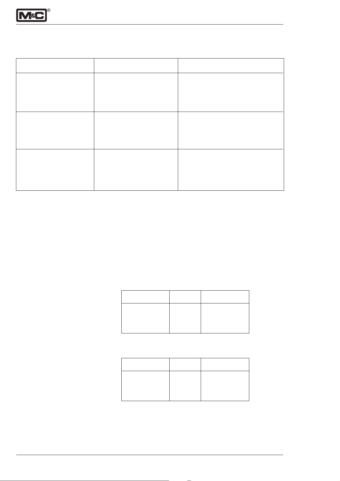
- 34 -
18.Trouble shooting
Fault description Display Solution
Measuring cell doesn‘t work E:01 resp. F:01, depending on Give air resp. nitrogen to the analyser
properly at 100 Vol.-% the language and restart the analyser
(suppressed measuring
range 99-100 Vol.-%)
Calibration fault:span gas is Display of the calibration fault Start new calibration.
switched off while proceed- until a new calibration is
ing the calibration of the carried out; the displayed value
span. is related to the last calibration.
Calibration limits of the A/D- Check the limits (see below) testing the
converter exeeded. converter channel (see menu);
When limits are exeeded a calibration at
the manufacturer has to be carried out.
Limits testing the converter channel (see menu):
Checking the zero point with nitrogen N
U
[V] U
min
max
[V]
2
0,005 0,147
Checking the span with ambient air (20,93 Vol.-%) at
normal pressure and different voltages of the zero point:
Zero point [V] U
[V] U
min
max
[V]
0,005 0,306 0,344
0,078 0,370 0,398
0,147 0,430 0,457
Checking the span with 100 Vol.-% oxygen O2 at normal
pressure and different voltages of the zero point:
Zero point [V] U
[V] U
min
max
[V]
0,005 1,440 1,580
0,078 1,470 1,610
0,147 1,500 1,630
M&C Products Analysentechnik GmbH 9-3.12-ME
Page 35
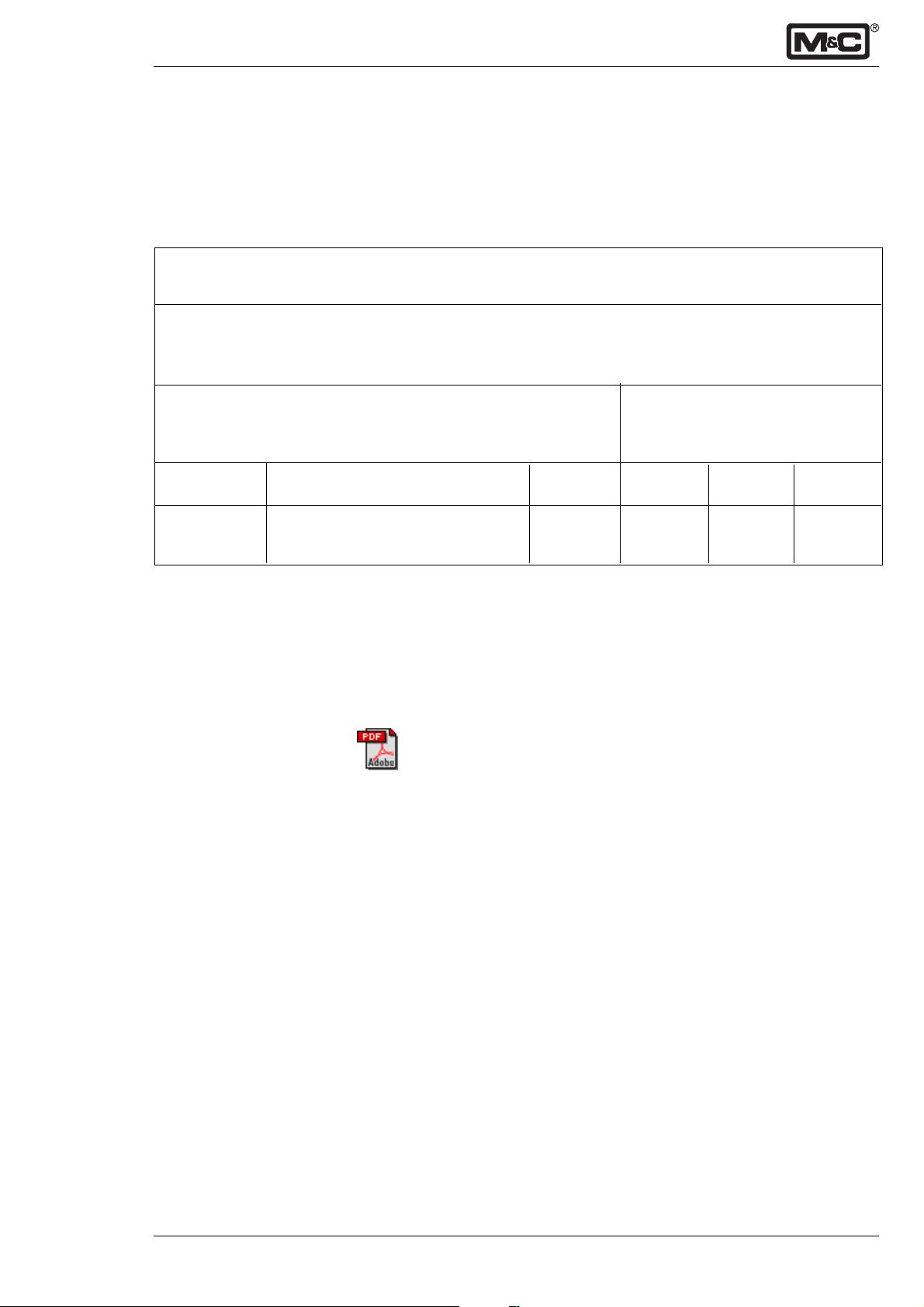
- 35 -
19.Spare part list
Wear, tear and replacement part requirements depend on
specific operating conditions. The recommended quantities
are based on experience and are not binding.
Oxygen Analyser Type PMA100
(C) consumable parts
(R) recommended spare parts
(S) Spare parts
recommended quantity PMA being
in operation
(years)
Part.-No. Indication C/R/S 1 2 3
90 A 0010 Measuring cell PMC1 S - - 1
90 A 0015 Flowmeter glass 7-70 Nl/hr S - - 1
20.Appendix
For further documentation:
Look on our homepage:
www.muc-products.de
9-3.12-ME M&C Products Analysentechnik GmbH
 Loading...