

Page 1
Operating Manual
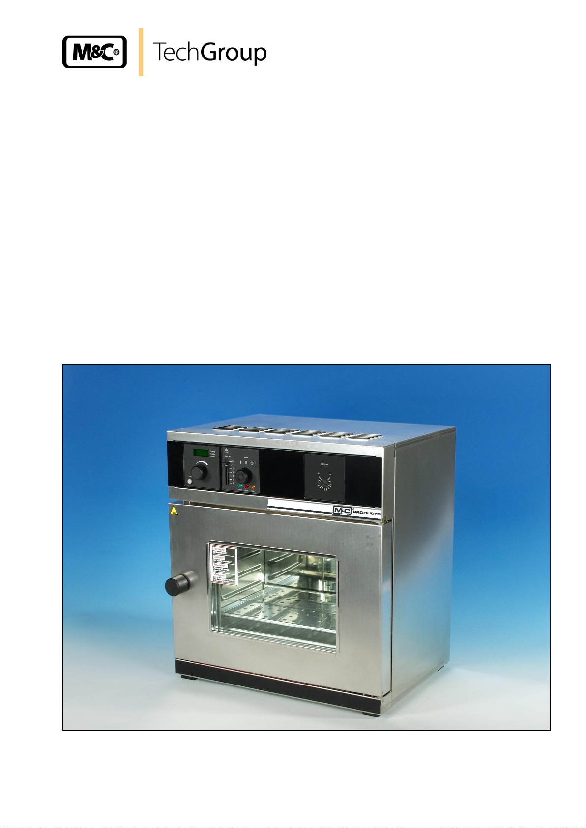
Heated protective housing
Series PAS-100 to PAS-500
Gas sampling and gas conditioning technology 10-5.1-ME
Page 2

2
This Operating Manual does not claim completeness and may be
subject to technical modifications.
© 06/2005 M&C TechGroup Germany GmbH. Reproduction of this
document or its content is not allowed without permission from M&C.
1st Edition: 06/2005
Dear customer,
we have made up this operating manual in such a way that all necessary information about the
product can be found and understood quickly and easily.
Should you still have any question, please do not hesitate to contact M&C directly or go through your
appointed dealer. Respective contact addresses are to be found in the annexe to this operating
manual.
Please also contact our homepage www.mc-techgroup.com for further information about our
products. There, you can read or download the data sheets and operating manuals of all M&C
products as well as further information in German, English and French.
Gas sampling and gas conditioning technology 10-5.1-ME
Page 3

3
List of Contents
1 General information ....................................................................................................................... 4
2 Declaration of conformity ............................................................................................................. 4
3 Safety instructions ........................................................................................................................ 5
4 Warranty ......................................................................................................................................... 5
5 Used terms and signal indications .............................................................................................. 6
6 Introduction .................................................................................................................................... 7
7 Serial number ................................................................................................................................. 7
8 Voltage supply ............................................................................................................................... 7
9 Warnings and notes ...................................................................................................................... 7
10 Technical Data ............................................................................................................................... 8
11 Application ..................................................................................................................................... 9
12 Description ..................................................................................................................................... 9
13 Aufbau .......................................................................................................................................... 10
13.1 Basic equipment of the heated protective housings ............................................................. 10
13.2 Material quality ...................................................................................................................... 11
13.3 Electrical equipment ............................................................................................................. 11
13.4 Supply failure ........................................................................................................................ 11
14 Reception and storage ................................................................................................................ 11
15 Preparation for mounting ............................................................................................................ 11
15.1 Installation facilities (accessories) ........................................................................................ 12
15.2 Wall bracket .......................................................................................................................... 12
16 Operating ...................................................................................................................................... 13
16.1 Operating the door ................................................................................................................ 13
16.2 Controls and indications ....................................................................................................... 13
16.3 Switching on ......................................................................................................................... 14
16.4 Setting air changes ............................................................................................................... 14
16.5 Setting the temperature ........................................................................................................ 14
16.6 Selecting the operating mode ............................................................................................... 14
16.7 Normal operation .................................................................................................................. 15
16.8 Timer operation ..................................................................................................................... 15
16.9 Temperature monitor and protection devices ....................................................................... 15
16.9.1 Temperature limiter (TB) ................................................................................................ 15
16.9.2 Monitor relay .................................................................................................................. 16
17 Starting ......................................................................................................................................... 16
18 Maintenance ................................................................................................................................. 17
18.1 Cleaning ................................................................................................................................ 18
19 Closing down ............................................................................................................................... 18
20 Error massages ............................................................................................................................ 18
21 Option low temperature alarm .................................................................................................... 19
22 Annexe .......................................................................................................................................... 19
List of Illustrations
Figure 1 Dimensions ......................................................................................................................... 8
Figure 2 Design of the protective housing ...................................................................................... 10
Figure 3 Minimum dimensions for mounting resp. installation ........................................................ 12
Figure 4 Wall bracket ...................................................................................................................... 13
Figure 5 Operating the door ............................................................................................................ 13
Figure 6 Controls and indications ................................................................................................... 13
Figure 7 Function of the monitor relay ............................................................................................ 16
Figure 8 Arrangement of the temperature sensor ........................................................................... 17
Figure 9 Layout of the door hinge ................................................................................................... 18
Figure 10 Wiring plan for low temperature alarm .............................................................................. 20
Gas sampling and gas conditioning technology 10-5.1-ME
Page 4

4
Head Office
M&C TechGroup Germany GmbH Rehhecke 79 40885 Ratingen Germany
Telephone: 02102 / 935 - 0
Fax: 02102 / 935 - 111
E - mail: info@mc-techgroup.com
www.mc-techgroup.com
1 GENERAL INFORMATION
The product described in this operating manual has been examined before delivery and left our works
in perfect condition related to safety regulations. In order to keep this condition and to guarantee a
safe operation, it is important to heed the notes and prescriptions made in this operating manual.
Furthermore, attention must be paid to appropriate transportation, correct storage, as well as
professional installation and maintenance work.
All necessary information a skilled staff will need for appropriate use of this product are given in this
operating manual.
2 DECLARATION OF CONFORMITY
CE - Certification
The product described in this operating manual complies with the following EC directives:
EMV-Instruction
The requirements of the EC directive 2004/108/EC “Electromagnetic compatibility“ are met.
Low Voltage Directive
The requirement of the EC directive 2006/95/EC “Low Voltage Directive“ are met.
The compliance with this EC directive has been examined according to DIN EN 61010.
Declaration of conformity
The EU Declaration of conformity can be downloaded from the M&C homepage or directly requested
from M&C.
Gas sampling and gas conditioning technology 10-5.1-ME
Page 5

5
3 SAFETY INSTRUCTIONS
Please take care of the following basic safety procedures when mounting, starting up or
operating this equipment:
Read this operating manual before starting up and use of the equipment. The information and
warnings given in this operating manual must be heeded.
Any work on electrical equipment is only to be carried out by trained specialists as per the regulations
currently in force.
Attention must be paid to the requirements of VDE 0100 (IEC 364) when setting high-power electrical
units with nominal voltages of up to 1000 V, together with the associated standards and stipulations.
Check the details on the type plate to ensure that the equipment is connected to the correct mains
voltage.
Protection against touching dangerously high electrical voltages:
Before opening the equipment, it must be switched off and hold no voltages. This also applies to any
external control circuits that are connected.
The device is only to be used within the permitted range of temperatures and pressures.
Check that the location is weather-protected. It should not be subject to either direct rain or moisture.
The device must not be used in hazardous areas.
Installation, maintenance, monitoring and any repairs may only be done by authorized personnel with
respect to the relevant stipulations.
4 WARRANTY
If the equipment fails, please contact M&C directly or else go through your M&C authorised dealer.
We offer a one year warranty as of the day of delivery as per our normal terms and conditions of sale,
and assuming technically correct operation of the unit. Consumables are hereby excluded. The terms
of the warranty cover repair at the factory at no cost or the replacement at no cost of the equipment
free ex user location. Reshipments must be send in a sufficient and proper protective packaging.
Gas sampling and gas conditioning technology 10-5.1-ME
Page 6
6
DANGER!
This means that death, severe physical injuries and/or important
material damages will occur in case the respective safety measures
are not fulfilled.
W ARN IN G !
This means that death, severe physical injuries and/or important
material damages may occur in case the respective safety
measures are not fulfilled.
CARE!
This means that minor physical injuries may occur in case the
respective safety measures are not fulfilled.
CAR E!
Without the warning triangle means that a material damage may
occur in case the respective safety measures are not met.
ATT ENT ION !
This means that an unintentional situation or an unintentional status
may occur in case the respective note is not respected.
NOTE!
These are important information about the product or parts of the
operating manual which require user’s attention.
SKILLED STAFF
These are persons with necessary qualification who are familiar with
installation, use and maintenance of the product.
5 USED TERMS AND SIGNAL INDICATIONS
Gas sampling and gas conditioning technology 10-5.1-ME
Page 7

7
NOTE!
In case of any question, please always indicate the serial number of the
device.
NOTE!
The notes and warnings given in this Operating Manual must absolutely be
heeded!
6 INTRODUCTION
A big problem of the extractive continuous gas analysis are the escort substances of the gas, such as
water vapour as well as gas components that produce corrosive acids in connection with condensed
water vapour.
In order to realise a maintenance-free resp. “hot” measurement, the condensation of water vapour and
gas components within the gas conditioning must be prevented.
The solution for this problem are the heated M&C sample conditioning units PAS. If these systems are
correctly adapted to the local process conditions, they guarantee a minimum maintenance
requirement.
7 SERIAL NUMBER
The type plates with the serial numbers are to be found down on the right side behind the door.
8 VOLTAGE SUPPLY
The heated protective housings PAS are available in 115V or 230V execution. Detailed information
are to be read on the type plate.
9 WARNINGS AND NOTES
Gas sampling and gas conditioning technology 10-5.1-ME
Page 8

10 TECHNICAL DATA
Mains plug
Heated protective housing
Series PAS
PAS-100
PAS-200
PAS-300
PAS-400
PAS-500
Assembly interior:
Width A mm
320
400
480
400
560
Height B mm
240
320
320
400
480
Depth C mm
175
250
250
330
400
External dimensions
Width D mm
470
550
630
550
710
Height E mm
520 (720)*
600 (800)*
600 (800)*
680 (800)*
760 (960)*
Depth F mm
325
400
400
480
550
Weight empty kg
20
28
30
35
50
Ventilator
no
no
no
yes
yes
Power consumption
600W
1100W
1200W
1400W
2000W
Power supply
230V 50/60Hz other voltages on request
Electrical connection
3m mains cable with an earthing-pin plug; a suitable terminal box is provided for built-in components
Material of cabinet
Stainless steel 304
Mounting
Wall-mounting with optional wall console
Temperature control
Electronically, microprocessor controlled, incl. a solid-state relay
Temperature display
Digital LED display
Temperature limit
Temperature selection control and limiter in accordance with DIN 12880, protective classification 3.1
Temperature selection
Lockable rotary button, range: +20 to +200°C *Standard
Operating temperature
>5°C above ambient temperature up to +200°C
Ambient temperature
Max. +40°C
Case protection
IP20 EN 60529
Options:
Observation window in door
External temperature control (2xPT100 internal)
Min.-temperature monitoring, potential free, contact rating 250VAC 16A
EEx-explosion-proof heating up to +120°C inner operating temperature
Steam heating
Wall bushings for sample pipes
Built-in components specific to the system
Figure 1 Dimensions
8
Dimensions in () are corresponding to the total height incl. the wall console
Gas sampling and gas conditioning technology 10-5.1-ME
Page 9

9
11 APPLICATION
Heated M&C sample conditioning systems are used where increased and constant operating
temperatures are necessary for the analysis of gases or liquids.
The large M&C product range of heatable components, in connection with the heated PAS-...
protective housing, allows you to solve problems specific to your applications.
12 DESCRIPTION
The conditioning components are housed in the protective cabinet (wall mounting) made of stainless
steel, which is heat insulated on all sides. The front door with its single-knob lock enables easy access
to the accommodated components. An observation window made of triple safety glass is available as
an option.
The heating of the cabinet is selectable within the range of +20 to +200 °C. An exact, electronic
control unit keeps the temperature constant at ±1 °C. The temperature is displayed digitally. Two
monitoring devices (temperature selection control and temperature limiter), which are fitted
additionally, ensure safe operation. In order to distribute the temperature, a ventilator is fitted
additionally into models of size PAS-400 and above. Depending on individual requirements the
following components can be installed:
• Filters
• Solenoid valves
• Valves, manually or pneumatically operated
• Ball valves, manually or pneumatically operated
• Flow meters with a needle valve and a mono stable flow control
• Pumps (pump head inside heated part, motor outside)
• Customised parts
Suitable bushings into the heated interior are provided for the heated sample lines.
Gas sampling and gas conditioning technology 10-5.1-ME
Page 10

10
13 AUFBAU
The devices PAS100 - 300 have natural ventilation.
In series PAS400 – 500 air circulation is provided by a fan on the back wall of the chamber.
The incoming air (1) is warmed in a preheat chamber (2) in both convection and fan-circulation ovens.
The preheated air enters the chamber (4) through ventilation slots (3) in the chamber side wall. The
fan (5) on the chamber back wall produces a large air throughput and a more intensive horizontal
forced circulation compared with natural convection. The air valve (6) on the back of the oven controls
the rate of air intake and discharge (air change) (7).
Figure 2 Design of the protective housing
13.1 BASIC EQUIPMENT OF THE HEATED PROTECTIVE HOUSINGS
Electronic PID controller with permanent power matching, auto-diagnostic system for rapid fault
finding (see chapter 15 “Error messages“)
Manually adjustable air valve for re-circulation or fresh air operation
Programmable electronic switch-off timer up to 99 h 59 min
Recessing push/turn control for simple operation of oven
Visual alarm indication
Monitor relay to switch off heating in case of fault
Mechanical temperature limiter (TB Class 1)
High-grade PT100 temperature sensor Class A in 4-wire circuit
Wall bracket
Gas sampling and gas conditioning technology 10-5.1-ME
Page 11

11
NOTE!
Any work involving opening up the housing must only be carried out by
skilled staff!
NOTE!
The heated protective housing must be stored in a weather-protected frost-
free area!
13.2 MATERIAL QUALITY
The external casing and working chamber is out of stainless steel 1.4301 which features high strength,
optimum hygienic properties and corrosion resistance against many (not all) chemicals (warning
against e.g. chlorine compounds). The oven load has to be checked carefully for its chemical
compatibility with the above materials.
13.3 ELECTRICAL EQUIPMENT
Operating voltage see label 50/60 Hz
Current rating see label
Protection Class 1, i.e. operating isolation with ground connection to EN 61 010
Protection IP20 to EN 60 529
Interference suppression to EN55011 Class B
Oven protected by a fuse 250V/15A fast blow
Controller protected by an 80 mA fuse (200 mA on 115 V)
When connecting the device to the electrical supply you have to observe any local
regulations which apply (e.g. in Germany DIN VDE 0100 with FI protection circuit)
13.4 SUPPLY FAILURE
After a failure of the supply, operation is continued with the same parameter settings.
14 RECEPTION AND STORAGE
Carefully remove the heated protective housing and eventual accessories out of the packing
immediately on arrival and inspect the contents of supply against the packing list;
Check the items for any damage in transit and, if required, inform the shipping insurance company
immediately of the damage found;
15 PREPARATION FOR MOUNTING
Before installing the heated protective housing, an easy access for maintenance and space for
adequate ventilation must be considered.
Check whether the mains voltage corresponds to the indication on the type plate.
Check whether the materials in touch with the sample are resistant.
Gas sampling and gas conditioning technology 10-5.1-ME
Page 12

12
W ARN IN G !
Do not place the device on a readily inflammable support surface!
15.1 INSTALLATION FACILITIES (ACCESSORIES)
The heated protective housing can be placed on the floor or on a bench (working surface). It is
important that the oven is set up accurately horizontally; the door may have to be adjusted (see
chapter 13 „Maintenance“).
The spacing from the back of the heated protective housing to the wall should be at least 15 cm. The
spacing to the ceiling must not be less than 20 cm and that at the side to the wall not less than 8 cm.
Generally it is essential to have adequate air ventilation around the housing.
Figure 3 Minimum dimensions for mounting resp. installation
15.2 WALL BRACKET
The models PAS-200 to PAS-500 can be wall-mounted using the wall bracket. The wall bracket is
factory-fitted with a fire-resistant plate. The suitable mounting material is attached to the range of
delivery.
Gas sampling and gas conditioning technology 10-5.1-ME
Page 13

13
Figure 4 Wall bracket
16 OPERATING
16.1 OPERATING THE DOOR
The door is opened by pulling on the door handle.
The door is closed by the door handle being pushed in.
Figure 5 Operating the door
16.2 CONTROLS AND INDICATIONS
Figure 6 Controls and indications
Gas sampling and gas conditioning technology 10-5.1-ME
Page 14

14
16.3 SWITCHING ON
The heating is switched on by pressing the push/turn control.
Heating switched off. The push/turn control is Heating switched on and can be operated
using the pushed in and protected against damage push/turn control and the SET key.
16.4 SETTING AIR CHANGES
Moving the air slider opens and closes the air valve to control the supply and discharge of air.
Air valve closed Air valve open
16.5 SETTING THE TEMPERATURE
Hold down the SET key and set the temperature set point with the push/turn control. After the SET key
has been released the display briefly flashes the temperature set point. The display then changes to
the actual current temperature and the controller starts to control to the selected temperature
set point.
16.6 SELECTING THE OPERATING MODE
Normal Timer
Operation Operation
After holding down the SET key (approx. 3 sec), the current operating mode flashes on the display. A
different operating mode can be selected with the push/turn control while the SET key is being held
down. After the SET key has been released the controller operates in the new operating mode.
Gas sampling and gas conditioning technology 10-5.1-ME
Page 15

15
16.7 NORMAL OPERATION
In this operating mode the heated protective housing operates continuously and heats and controls to
the set temperature. On the PAS-400 – 500 the fan is running continuously.
Setting the temperature:
Hold down the SET key and set the required temperature set point with the push/turn control.
After the SET key has been released the display flashes briefly the temperature set point.
The display then changes to the actual current temperature and the controller starts to control to the
selected temperature set point.
16.8 TIMER OPERATION
In this operating mode the heated protective housing operates on the timer; it heats/controls to the set
temperature and maintains this temperature until the set time has elapsed. The clock symbol is
flashing during timer operation, then the heating is switched off; on PAS-400 – 500 the fan runs on for
30 minutes. The timer display shows END.
- The time can always be set to OFF, the heating is then switched off and the timer display shows
END.
- Time is counted down, it is always possible to see how long the heated protective housing will
remain switched on.
Setting the temperature:
Turn the push/turn control clockwise until the temperature display is flashing.
Hold down the SET key and set the required temperature set point with the push/turn control.
After the SET key has been released the oven flashes briefly the temperature set point. The display
then changes to the actual temperature and the controller starts to control to the selected temperature
set point.
Setting the timer:
Turn the push/turn control anticlockwise until the timer display is flashing.
Hold down the SET key and set the required operating time with the push/turn control.
16.9 TEMPERATURE MONITOR AND PROTECTION DEVICES
16.9.1 TEMPERATURE LIMITER (TB)
All devices are equipped with a mechanical temperature limiter (TB) Protection Class 1 to DIN 12 880.
If the electronic monitor system should fail during operation and the fixed factory-set maximum
temperature is exceeded by approx. 20°C the temperature limiter switches off the heating permanently
as a final protective measure. The alarm symbol lights up as warning.
Fault rectification after the TB cut-out has been activated:
1. Switch off the heating and allow it to cool down
2. Rectify the fault (e.g. replace temperature probe) and where appropriate contact customer service
3. The oven is again ready for operation only after it has cooled down and after the fault has been
rectified.
Gas sampling and gas conditioning technology 10-5.1-ME
Page 16

16
emergency mod
16.9.2 MONITOR RELAY
In addition to mechanical temperature protection the heated protective housing is provided with an
electronic monitor relay.
If a fault occurs during operation or if the selected set point temperature is exceeded by 10°C the
monitor relay switches over the heating to this temperature in emergency mode. The alarm symbol is
flashing as warning.
Fault rectification after the monitor relay may been activated:
Check the controller for error messages (see chapter 15 „Error messages“) and where appropriate
contact customer service.
Example:
With a set point
temperature of 150°C, if
a fault occurs in the
power unit (faulty triac)
the oven continues to
operate in emergency
operation at approx.
160°C.
Figure 7 Function of the monitor relay
17 STARTING
During operation and maintenance works, the following prescriptions have to be observed:
- the Operating Manual
- the standard EN 60519-1 „Safety in Electrical Heating Facilities“ Part 1: General Requirements
- the standard EN 60519-2 „Safety in Electrical Heating Facilities“ Part 2: Special Instructions for
Facilities with Resistance Heating
- the standard VDE 0100 or similar regional prescriptions
- eventually applicable standards and prescriptions (i.e. Employer’s liability insurance association in
Germany).
When the heated protective housing is started up for the first time, it should be supervised
continuously until steady conditions have been reached. Severe vibrations during transport may cause
movement of the temperature probe in its holder inside the chamber. Note therefore that before the
first start-up the temperature probe should be checked for its correct position and, if necessary,
carefully aligned in its mounting (see figure 8).
Gas sampling and gas conditioning technology 10-5.1-ME
Page 17

17
NOTE!
Any work involving opening up the oven must only be carried out by skilled
staff!
Figure 8 Arrangement of the temperature sensor
There must be no possibility of the formation of inflammable gas/air mixtures either within the oven
chamber or in the immediate surroundings of the equipment.
Large amounts of dust or corrosive fumes inside the oven chamber or in the surroundings of the
equipment may produce deposits within the oven and lead to short-circuits or damage the electronics.
It is therefore important that adequate precautions are taken against excessive dust or corrosive
fumes.
18 MAINTENANCE
Important for a long life of the heated protective housing and in case of warranty claims.
The heated protective housings require little maintenance. It is however recommended to lubricate all
moving parts of the doors (hinges and closure) once a year (or 4 times a year with continuous
operation) using a thin Silicone grease, and to check that the hinge screws are tight. A well-closing
door is essential on an heated protective housing. On the housings, tight closure of the door is
ensured by a seal on the oven and another one on the door. In continuous operation the flexible
sealing material may take a permanent set. Readjustment may then be necessary in order to ensure
proper closing of the door.
Gas sampling and gas conditioning technology 10-5.1-ME
Page 18

18
The top part (1) of the door hinge can, after releasing
the 2 screws (2) at the top or bottom of the door, be
moved slightly in the direction of the arrow.
The door can be adjusted after releasing the socket
screw (3) and rotating the eccentric (4) by means of
a screwdriver. NOTE ! Screw (3) is locked with locking
varnish. It can be released by a sharp tug using a
hexagon socket key. Apply more locking varnish to
screw (3) and tighten it.
The closing panel (6) can also be adjusted in the
direction of the arrow after releasing the screw (5). It is
important that the panel is then screwed down firmly.
Figure 9 Layout of the door hinge
18.1 CLEANING
Regular cleaning of the easy-to-clean inside of the chamber prevents deposits which over time can
detract from the appearance and the functionality of the stainless steel chamber .
The metal surfaces of the oven can be cleaned with commercially available cleaning agents for
stainless steel. It is important to ensure that no rust-forming object comes into contact with the
chamber or the stainless steel casing. Rust deposits cause infection of the stainless steel.
If any contamination causes rust stains on the surfaces of the chamber, such spots must be cleaned
off immediately and the area polished. The control panel, the plastic input modules and other plastic
components of the heated protective housing must not be cleaned using scouring cleaning agents or
those contained solvents.
19 CLOSING DOWN
Before closing down, i.e. switching off the heating, the heated gas conditioning system and if
necessary the interior of the heated protective housing should be purged with inert gas or air in order
to avoid a condensation and an eventual acidification.
20 ERROR MASSAGES
E-0 Error on self test
E-1 Power module triac faulty
E-2 Power module faulty
E-3 PT100 temperature probe faulty
Gas sampling and gas conditioning technology 10-5.1-ME
Page 19

19
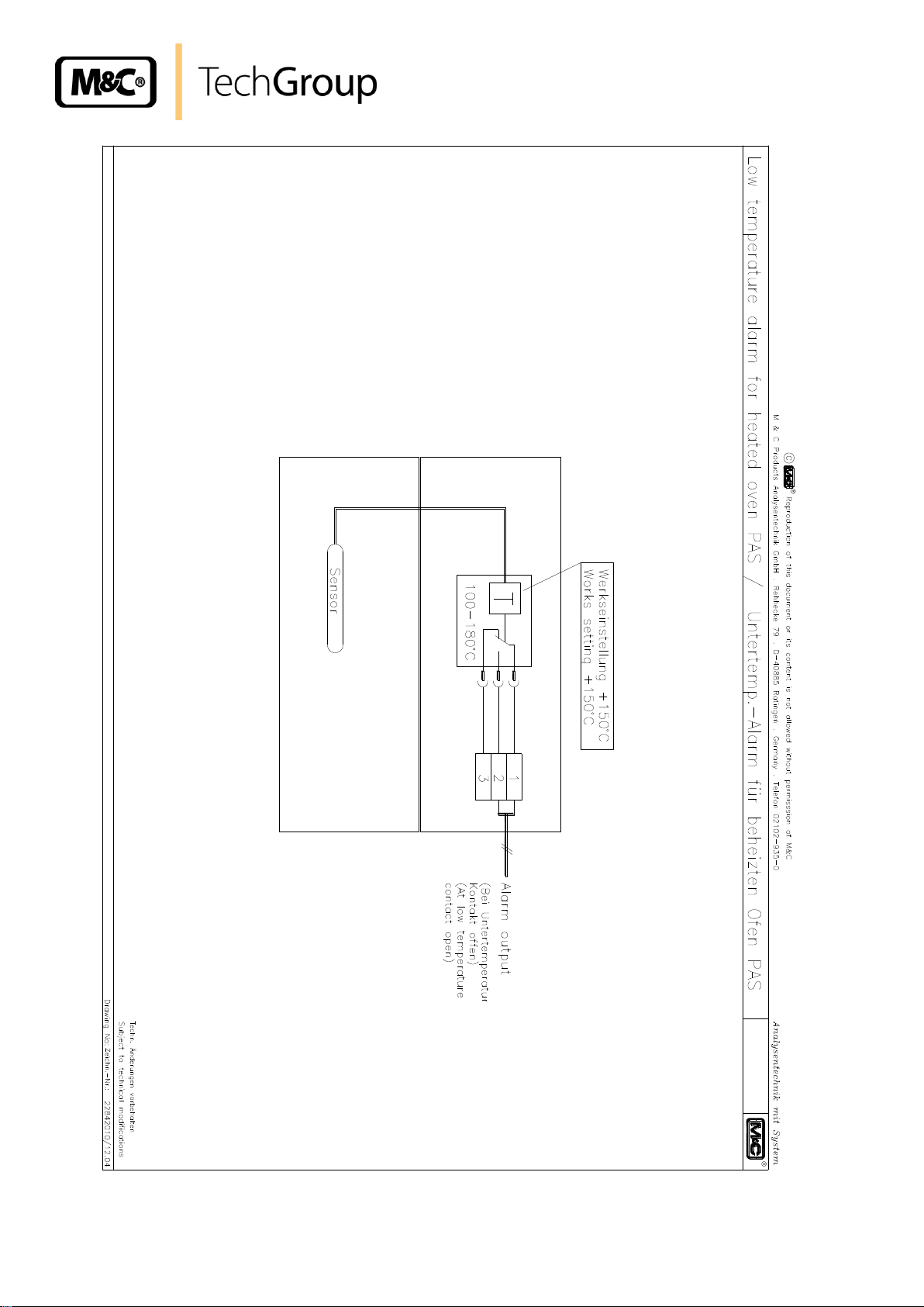
21 OPTION LOW TEMPERATURE ALARM
The heated protective housing PAS can be controlled by a low temperature alarm contact.
The sensor is fixed to the ceiling of the inner oven. The controller of this thermostat is installed in the
top of the oven under the top cover.
The range of temperature setting is from 100 – 180°C. The standard controller setting is at +150°C.
The contact is closed during normal operation and opens when the temperature decreases <150°C.
The contact rating is 230V AC, 16A.
To change controller setting, unscrew the 4 screws at the top of the rear side of the housing and take
the cover of. Put the knob of the controller to the desired temperature on the scale. Close the cover.
22 ANNEXE
Wiring plan low temperature alarm drawing no.: 22842010
Further product documentation can be seen and downloaded from our home page:
www.mc-techgroup.com
Gas sampling and gas conditioning technology 10-5.1-ME
Page 20
20
Figure 10 Wiring plan for low temperature alarm
Gas sampling and gas conditioning technology 10-5.1-ME
 Loading...