

Page 1
Operating Manual
Bellows pump series MP®-F
Version MP-F05, MP-F05/R, MP-F10, MP-F10/R
Gas sampling and gas conditioning technology 10.1a-ME
Page 2

List of content
1 General information ....................................................................................................................... 4
2 Declaration of conformity ............................................................................................................. 4
3 Safety instructions ......................................................................................................................... 5
4 Warranty ......................................................................................................................................... 5
5 Used terms and signal indications ............................................................................................... 6
6 Introduction .................................................................................................................................... 7
7 Description ..................................................................................................................................... 7
8 MP-F05/R and MP-F10/R with integrated needle valve type /R for adjustment of the
pump capacity ................................................................................................................................ 7
9 Technical data ................................................................................................................................ 8
9.1 Pump capacities ........................................................................................................................... 9
9.2 Dimensions .................................................................................................................................. 9
10 Receipt of goods and storage .................................................................................................... 10
11 Installation instructions .............................................................................................................. 10
11.1 Ambient conditions ..................................................................................................................... 11
11.2 Pump mounting .......................................................................................................................... 11
11.3 Turning of the pump head .......................................................................................................... 11
11.4 Supply connections .................................................................................................................... 12
11.4.1 Electrical connections ...................................................................................................... 12
11.4.2 Pneumatic connection ..................................................................................................... 14
12 Start up ......................................................................................................................................... 14
13 Closing down ............................................................................................................................... 15
14 Maintenance ................................................................................................................................. 15
14.1 Exchange of the valve plates ..................................................................................................... 16
14.2 Exchange of the bellows ............................................................................................................ 16
14.3 Cleaning ..................................................................................................................................... 16
15 Trouble shooting .......................................................................................................................... 17
16 Spare parts list ............................................................................................................................. 18
17 Annexe .......................................................................................................................................... 18
List of illustrations
Figure 1 Bellows pump with needle valve type MP-F../R .................................................................... 8
Figure 2 Pump capacity MP-F05 and MP-F10 .................................................................................... 9
Figure 3 Dimensions (mm) MP-F../R .................................................................................................. 9
Figure 4 Mounting of MP-F.. .............................................................................................................. 11
Figure 5 Turning pump head ............................................................................................................. 12
Figure 6 Electrical connection ........................................................................................................... 13
Figure 8 Sectional drawing MP-F.. .................................................................................................... 16
2 Gas sampling and gas conditioning technology 10.1a-ME
Page 3

This Operating Manual does not claim completeness and may be
subject to technical modifications.
© 03/2013 M&C TechGroup Germany GmbH. Reproduction of this
document or its content is not allowed without permission from M&C.
MP® is a registered trade mark.
1st Edition: 03/2013
Dear customer,
we have made up this operating manual in such a way that all necessary information about the product can be found and understood quickly and easily.
Should you still have any question, please do not hesitate to contact M&C directly or go through your
appointed dealer. Respective contact addresses are to be found in the annexe to this operating manual.
Please also contact our homepage www.mc-techgroup.com for further information about our products. There, you can read or download the data sheets and operating manuals of all M&C products as
well as further information in German, English and French.
10.1a-ME Gas sampling and gas conditioning technology 3
Page 4

Head Office
M&C TechGroup Germany GmbH Rehhecke 79 40885 Ratingen Germany
Telephone: 02102 / 935 - 0
Fax: 02102 / 935 - 111
E - mail: info@mc-techgroup.com
www.mc-techgroup.com
1 GENERAL INFORMATION
The product described in this operating manual has been examined before delivery and left our works
in perfect condition related to safety regulations. In order to keep this condition and to guarantee a
safe operation, it is important to heed the notes and prescriptions made in this operating manual.
Furthermore, attention must be paid to appropriate transportation, correct storage, as well as professional installation and maintenance work.
All necessary information a skilled staff will need for appropriate use of this product are given in this
operating manual.
2 DECLARATION OF CONFORMITY
CE - Certification
The product described in this operating manual complies with the following EC directives:
EMV-Instruction
The requirements of the EC directive 2004/108/EC “Electromagnetic compatibility“ are met.
Low Voltage Directive
The requirement of the EC directive 2006/95/EC “Low Voltage Directive“ are met.
The compliance with this EC directive has been examined according to DIN EN 61010.
Declaration of conformity
The EU Declaration of conformity can be downloaded from the M&C homepage or directly requested
from M&C.
4 Gas sampling and gas conditioning technology 10.1a-ME
Page 5

3 SAFETY INSTRUCTIONS
Please take care of the following basic safety procedures when mounting, starting up or operating this equipment:
Read this operating manual before starting up and use of the equipment. The information and warnings given in this operating manual must be heeded.
Any work on electrical equipment is only to be carried out by trained specialists as per the regulations
currently in force.
Attention must be paid to the requirements of VDE 0100 (IEC 364) when setting high-power electrical
units with nominal voltages of up to 1000 V, together with the associated standards and stipulations.
Check the details on the type plate to ensure that the equipment is connected to the correct mains
voltage.
Protection against touching dangerously high electrical voltages:
Before opening the equipment, it must be switched off and hold no voltages. This also applies to any
external control circuits that are connected.
The device is only to be used within the permitted range of temperatures and pressures.
Check that the location is weather-protected. It should not be subject to either direct rain or moisture.
The Diaphragm-sample pumps MP-F05, MP-F05/R, MP-F10, MP-F10/R must not be used in hazard-
ous areas.
Installation, maintenance, monitoring and any repairs may only be done by authorized personnel with
respect to the relevant stipulations.
4 WARRANTY
If the equipment fails, please contact M&C directly or else go through your M&C authorised dealer.
We offer a one year warranty as of the day of delivery as per our normal terms and conditions of sale,
and assuming technically correct operation of the unit. Consumables are hereby excluded. The terms
of the warranty cover repair at the factory at no cost or the replacement at no cost of the equipment
free ex user location. Reshipments must be send in a sufficient and proper protective packaging.
10.1a-ME Gas sampling and gas conditioning technology 5
Page 6

DANGER!
This means that death, severe physical injuries and/or important
material damages will occur in case the respective safety measures
are not fulfilled.
WA RN I NG !
This means that death, severe physical injuries and/or important
material damages may occur in case the respective safety measures are not fulfilled.
CARE!
This means that minor physical injuries may occur in case the
respective safety measures are not fulfilled.
CA R E !
Without the warning triangle means that a material damage may
occur in case the respective safety measures are not met.
AT TE N TI O N!
This means that an unintentional situation or an unintentional status
may occur in case the respective note is not respected.
NOTE!
These are important information about the product or parts of the
operating manual which require user’s attention.
SKILLED STAFF
These are persons with necessary qualification who are familiar with
installation, use and maintenance of the product.
5 USED TERMS AND SIGNAL INDICATIONS
6 Gas sampling and gas conditioning technology 10.1a-ME
Page 7

W AR NIN G!
Bellows pumps series MP-F are not permitted for liquid media.
6 INTRODUCTION
The bellows pumps MP-F are suitable for 100% oil free gas delivery of corrosive gases. They are
designed especially in construction and performance for problems in the analysis technique. The
pumps are gas tight and work maintenance free.
7 DESCRIPTION
All sample contacting parts of the bellows pump MP-F are corrosion resistant. As option for piping the
upper pump head part is available in stainless steel. The pump works absolutely lubricant free, so
gases remain analytically unchanged. Due to a special bellows and valve system, the pump operates
maintenance-free with a long service life. The simple valve design guarantees low maintenance costs.
The pump is available in 230V or 115V and in two capacity variants:
MP-F05 pump capacity 5 Nl/min
MP-F10 pump capacity 10 Nl/min
Optional a needle valve can be build into the pump-head to adjust the flow rate.
Gas connection can be effected from above or laterally. The pump head also can be rotated and
mounted in 90° steps.
8 MP-F05/R AND MP-F10/R WITH INTEGRATED NEEDLE VALVE TYPE /R FOR
ADJUSTMENT OF THE PUMP CAPACITY
For adjustment of the pump capacity a needle valve is built into the pump head as an internal bypass.
Due to the optimal form of the valve needle the pump capacity can be adjusted within a wide range. All
media wetted parts of the valve are made of PTFE and PVDF. There are no o-rings present.
10.1a-ME Gas sampling and gas conditioning technology 7
Page 8
Bellows pump
MP-F05 /230V
MP-F05 /115V
MP-F10 /230V
MP-F10/115V
Part no.
05 P 1000
05 P 1000A
05 P 1005
02 P 1005A
Part no. with needle valve
MP-F../R
05 P 1010
05 P 1010A
05 P 1015
05 P 1015A
Voltage
230V 50Hz +/-5%
115V 60Hz +/-5%
230V 50Hz.+/-5%
115V 60Hz +/-5%
Capacity max.
5,0 l/min* pressureless
10 l/min* pressureless
Operating pressure
0,4 to 2,2 bar abs.
0,2 bis 3,2 bar abs.
Gas temperature
-30 to +100°C valid for dry gases
Protection class
IP 55 - DIN 40050
Ambient temperature
-20 to +40°C installation altitude < 1000m NN
Storage temperature
-20 to +60°C
Connection thread sample gas
G 1/4“ i
Gas tightness of pump head
< 6x10 -3 mbar l/s
Performance
65 W
Power consumption
0,30 A
0,57 A
0,30 A
0,57 A
Cable inlet
M20 x 1,5 clamping range 5,5 – 10mm
Electrical equipment standard
EN 60204-1
Media wetted parts
PTFE, PFA, FEP (+PVDF for type /R)
Weight
4,7 Kg
Options
05 P 1050
Mounting bracket with 4 anti-vibration pads for bellows pump MP-F
05 P 1060
Extra charge for upper pump head of bellows pump MP-F out of stainless steel
05 P 1070
Extra charge for upper pump head of bellows pump MP-F../R out of stainless steel
with needle valve out of PVDF
Figure 1 Bellows pump with needle valve type MP-F../R
9 TECHNICAL DATA
Material abbreviations according to ISO 1629 and 1043.1
8 Gas sampling and gas conditioning technology 10.1a-ME
Page 9

9.1 PUMP CAPACITIES
Figure 2 Pump capacity MP-F05 and MP-F10
9.2 DIMENSIONS
Figure 3 Dimensions (mm) MP-F..
10.1a-ME Gas sampling and gas conditioning technology 9
Page 10
NOTE!
The bellows pump should be stored in a protected, frost-free room!
NOTE!
The pump must only be used under conditions specified in the
technical data. The pump should be installed away from heat
sources and freely ventilated to prevent any accumulation of heat.
For outdoor installation, the pump must be installed in a housing
protected from frost in the winter and sufficiently ventilated in
summer. Exposure to direct sunlight must be avoided.
WA RN I NG !
It is therefore essential to provide protection for persons against
contact with live parts (e.g. electrical connections, motor windings)
and moving parts (e.g. fan). Protection against entry of foreign
bodies must also be provided.
WA RN I NG !
Pumps have mechanical moving parts that can induce vibrations.
To prevent damages at the pump or at peripheral components /
facilities as well as minimizing noise development an appropriate
vibration decoupling is necessary. For this M&C can deliver e.g.
anti-vibration pads.
This is also explicit valid for the connection of the sample lines at
the pump head.
WA RN I NG !
The components connected to the pumps have to be designed for
the pneumatic data of the pumps.
Observe the corresponding safety regulations when connecting the
pumps to the mains.
For the media to be pumped the corresponding safety regulations
have to be observed.
10 RECEIPT OF GOODS AND STORAGE
Please take the bellows pump and possible special accessories carefully out of the packaging
material immediately after arrival, and compare the goods with the items listed on the delivery
note!
Check the goods for any damage caused during delivery and, if necessary, notify your trans-
port insurance company without delay of any damage discovered.
11 INSTALLATION INSTRUCTIONS
When installing the pump make certain that accident prevention regulations and safety instructions
including those for subsequent operation are observed. The safety instructions in section 6.2 must be
observed.
The protection class of the pumps MP-F... is IP55 and so offer no protection against contact or foreign
bodies.
10 Gas sampling and gas conditioning technology 10.1a-ME
Page 11

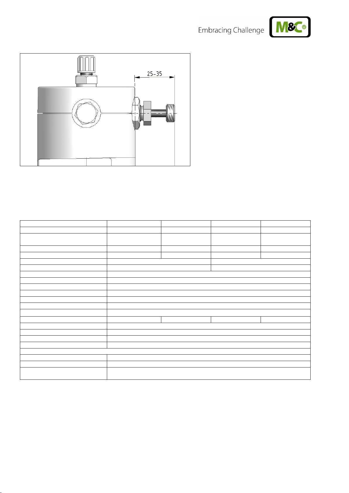
NOTE!
In order to increase the service life mount pumps at the highest
point of the system and/or with pump head pointing downwards
to prevent collection of condensate in the pump head.
min. distance 25mm
11.1 AMBIENT CONDITIONS
During operation the following ambient conditions must be complied with:
• Ambient temperature range during operation: -20 °C to +40 °C.
• The pumps have to be protected against water and dust influence.
• During operation a sufficient cooling air supply must be provided.
11.2 PUMP MOUNTING
Mounting dimensions are shown in Figure 3. For sufficient ventilation the pump has to be mounted
with a distance of min. 25mm to the wall.
Figure 4 Mounting of MP-F..
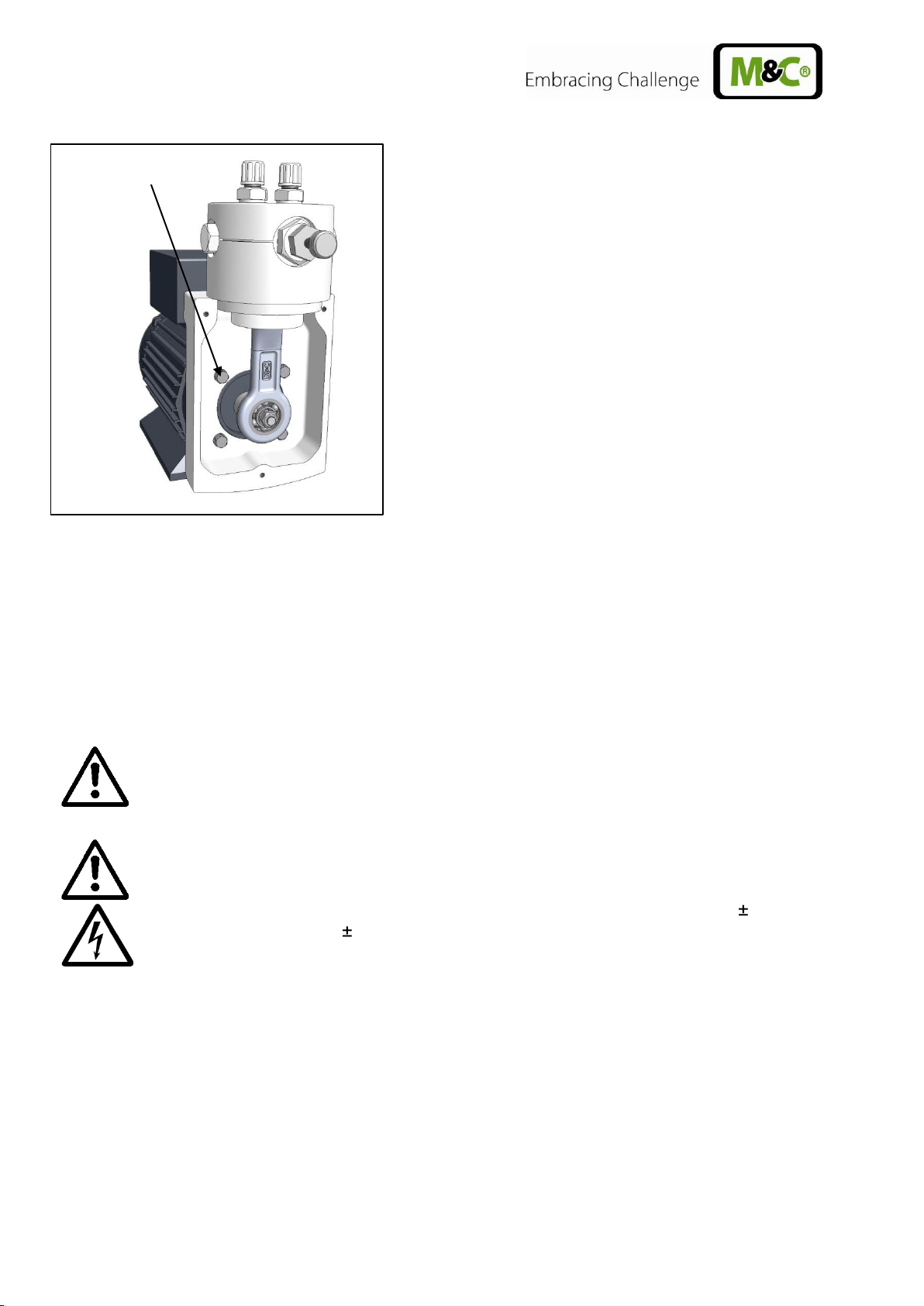
11.3 TURNING OF THE PUMP HEAD
By loosening the four flange screws the position of the pump head to the motor base can be changed
in 90° steps. For this operation proceed as follows:
• Loosen three lid screws.
• Remove lid.
• Now the four flange screws can be loosened (see Fehler! Verweisquelle konnte nicht ge-
funden werden.) and the pump head can be turned.
10.1a-ME Gas sampling and gas conditioning technology 11
Page 12
DANGER!
The bellows pumps MP F.. are not allowed to be operated in explo-
sive environments!
WA R NI NG !
Incorrect voltage can destroy the device.
When connecting the equipment, please ensure that the supply
voltage is identical with the information provided on the model type
plate. The supply voltage is only allowed to deviate max. 5 % and
frequency 2% from the indication on the model type plate.
Exceeding the tolerance increases the heating and influences the
electromagnetic compatibility.
The air-cooled motor is designed for an ambient temperature range
of -20 to +40°C as well as an installation altitude of
< 1000 m above mean sea level.
Flange screws
Figure 5 Turning the pump head
11.4 SUPPLY CONNECTIONS
11.4.1 ELECTRICAL CONNECTIONS
When making the electrical installation the safety regulations must be observed. In particular make
sure that the electricity supply is isolated before trying to connect the pump.
12 Gas sampling and gas conditioning technology 10.1a-ME
Page 13
NOTE!
For the erection of power installations with nominal voltages up to 1000V
the requirements of VDE 0100 and relevant standards and regulations must
be complied with!
The current supply circuit of pump type MP-F... (230 V) has to be provided
with a motor circuit braker 0,3A corresponding to the rated current (overcurrent protection).
The current supply circuit of pump type MP-F... (115 V) has to be provided
with a motor circuit braker 0,57A corresponding to the rated current (overcurrent protection).
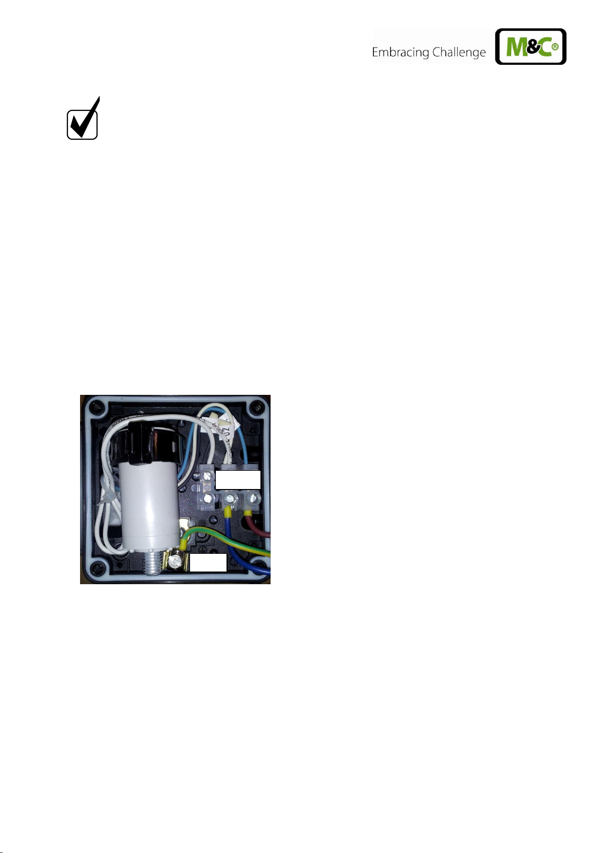
PE
N L
• Connect protective earth at pump motor.
• Built in a device into the electrical installation for isolation of the pump motor from mains supply
according to EN 60335-1.
• Install pumps so that touching live parts (e.g. electrical connection) is excluded.
• Unscrew lid of the connection box.
• Lead connection cable through cable gland (clamping range 5,5-10mm) and connect according
to Figure 6 or the drawing in the lid of the connection box.
Figure 6 Electrical connection MP-F..
10.1a-ME Gas sampling and gas conditioning technology 13
Page 14

11.4.2 PNEUMATIC CONNECTION
Remove protective plugs from the gas connection
threads (thread size G1/4“).
There is the possibility to screw in the tube connec-
tion fittings as well on top as on the side of the pump
head. For this remove protective plugs from the gas
connection threads on the side and screw in these on
top of the pump head.
Accessories like tube connection fittings are screwed
into the connection threads with sealing tape (when
using straight M&C connectors no sealing tape is
necessary). Connection fittings for DN4/6 or DN6/8
are available optionally by M&C.
Connect suction and pressure line. For this loosen
union nut of the compression ring fitting counter clockwise; care must be taken that the union
nut is carefully removed from the fitting body so that the loose clamping ring in the union nut is
not getting lost.
Slide the nut over the hose connection;
Slide the clamping ring with the thicker bulge facing the nut, onto the connection hose;
Attach the hose to the nipple in the threaded support;
Hand-tighten the nut. The hose is now mounted slip-proof and pressure-tight.
Lay suction and pressure line such a way that condensate can not flow into the pump.
12 START UP
Before commissioning, the plant and process-specific safety measures must to be observed !
Please note that the pumps may only be used for the intended purpose.
Specific safety instructions for media being handled must be observed. Before pumping a medium,
the compatibility of materials of pump head, diaphragm and valves with the medium must be checked
(for pump materials: see technical data). The following steps should be carried out before initial startup:
The pump must not start against pressure or vacuum.
When switching on the pressure in the suction and pressure lines must be atmospheric. This
must be so even when the pump restarts after the power has been cut off for a short period. At
pump standstill atmospheric pressure in the lines has to be established.
The maximum permissible operating pressure (see technical data chapter 9) must not be
exceeded, even when the flow is restricted.
14 Gas sampling and gas conditioning technology 10.1a-ME
Page 15

NOTE!
The area in which the pump is situated when it is not in use must
be kept free of frost at all times!
WA RN I NG !
It is necessary to take the pump off the mains before any assembly,
maintenance or repair work is carried out!
WA RN I NG !
Aggressive medium is possible.
Wear protective glasses and proper protective clothing during
disassembly, repair or cleaning!
To prevent the maximum permissible operating pressure being exceeded, restriction or control
of the air or gas flow should only be carried out in the suction line.
If restriction or control of the air or gas flow is made on the pressure side ensure that the
maximum permissible operating pressure is not exceeded.
Diaphragm and valve plates are the only parts subject to wear. Wear is usually indicated by a
drastic reduction in the pneumatic performance. When replacing parts proceed as described in
section 14.
13 CLOSING DOWN
When decomissioning no particular measures need to be taken.
14 MAINTENANCE
Before the maintenance work is carried out, it is necessary that the specific safety procedures pertaining to the system and operational process are observed!
Bellows and valve plates are the only parts of the pump subject to wear. They are simple to change.
For our recommendations for spare parts please refer to the spare parts list in chapter 16.
10.1a-ME Gas sampling and gas conditioning technology 15
Page 16
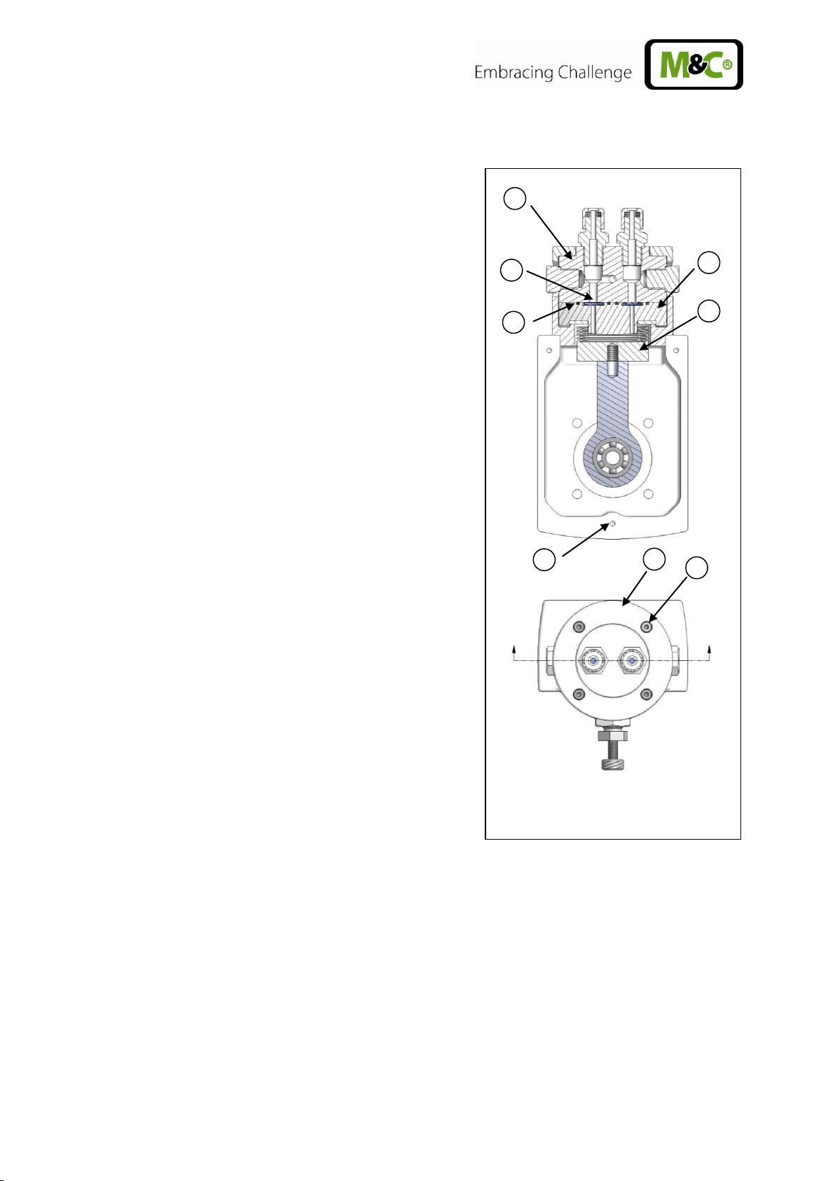
G F H D E A C
B
14.1 EXCHANGE OF THE VALVE PLATES
For the exchange of the valve plates the sample gas fittings
does not have to be dismounted.
Loosen the 4 hexagon socket screws G (key 3mm)
and remove pressure ring H.
Remove upper pump head A. O-rings C and valve
plates B are freely accessible now.
The valve plates and o-rings now can be cleaned or
exchanged. Clean valve seat and pump head with an
adequate solvent (e.g. alcohol) and blow out with
compressed air.
Valve B on the pressure side is looking downwards
with the smooth side and on the suction side with the
smooth side upwards (conveying direction is marked
with an arrow on the pump head).
Remounting happens in reverse order. Attention, en-
sure the correct position of the valve plates.
14.2 EXCHANGE OF THE BELLOWS
Carry out the steps from chapter 14.1 and remove
valves and o-rings.
Unscrew lid of the crankcase. For this loosen the 3
hexagon socket screws F (key 3mm).
Remove lower pump head D. If it is stuck a borehole in
the valve seat can be closed with a finger and pressure air be blown into the other one.
Unscrew the bellows E from the connection rod. Pay
attention to possibly present spacers. Leave these on
the threaded pin.
Screw new bellows hand tight on the connection rod.
Assembly happens in reverse order. Attention, ensure
the correct position of the valve plates!
Figure 7 Sectional drawing MP-F..
14.3 CLEANING
When changing valve plates and bellows, inspect all parts for dirt before assembling the pump
head and clean them if necessary.
Only use adequate solvents (e.g. alcohol) that plastic parts (PTFE, PFA, FEP) do not corrode.
If compressed air is available, blow out the parts.
16 Gas sampling and gas conditioning technology 10.1a-ME
Page 17

Problem/Indication
Possible cause
Check/Action
Pump produces no
flow
No main supply
Check power supply; Check plug for correct
fit
Connections or lines are
blocked
Remove blockade
An external valve is closed or
a filter is blocked
Open valve or clean dirty/blocked filter
Liquid (condensate) has collected in the pump head
Let pump convey air a few minutes
Flow, pressure or
vakuum too low
Diaphragm or valves are worn
Change diaphragm or/and valves
Compare the actual performance with the figures in chapter 9
The pump is not designed for this condition
There is pressure on the
pressure side and at the same
time vacuum on the suction
side
The pump is not designed for this condition
The cross-section of the
pneumatic lines or connected
components is too small, or
they are restricted
To measure the performance, disconnect the
pump from the system (smaller diameter
tubing or a valve can significantly affect
performance)
A leak at the connectors, lines
or pump head. Bellows or
valve plate is damaged or
pump head is contaminated
Insulate the leak, tighten the screws, clean
or exchange contaminated parts
15 TROUBLE SHOOTING
Before working on the pump isolate the power supply securely, then check that the lines are not live.
10.1a-ME Gas sampling and gas conditioning technology 17
Page 18

Bellows pump MP-F05, MP-F10, MP-F05/R, MP-F10/R
(C) Consumable parts
(R) Recommended spare parts
(S) Spare parts
Recommended quantity
being in operation [years]
Part No.
Description
C/R/S 1 2
3
95P0010
Bellows MP-F PTFE
C - -
1
90P1110
Valve plate MP-F
C 2 4
6
95P0035
O-ring FEP 18x2 MP-F
R 2 4
6
95P0030
Lower pump head MP-F
S - -
-
95P0025
Upper pump head MP-F
S - -
-
95P0040
Connection rod with eccentric and ball bearring
for MP-F05
S - -
-
95P0045
Connection rod with eccentric and ball bearring
for MP-F10
S - -
-
95P0026
Pump head MP-F above with borehole for needle
valve, material: PTFE
S - -
-
90P6030
Needle valve for MP-F../R
Sealing ring and needle out of PTFE
S - -
-
90P6015
Spare needle out of PTFE
for MP-F../R
S - -
-
90P6020
Sealing ring out of PTFE
for needle valve in MP-F../R
S - -
-
90P6025
Adapter out of PTFE
for needle valve in MP-F/R
S - -
-
PVDF male connectors with G-thread (ISO 1010031)
05V1060
Straight male connector DN 4/6-G1/4”
material: PVDF
S - -
-
05V1065
Straight male connector DN 6/8-G1/4”
material: PVDF
S - -
-
05V6600
Verrule DN 4/6, PVDF
S 1 2
3
05V6602
Verrule DN 6/8, PVDF
S 1 2
3
05V6605
Ünion nut DN 4/6, PVDF
S 1 2
3
05V6607
Ünion nut DN 6/8, PVDF
S 1 2
3
16 SPARE PARTS LIST
Wear, tear and replacement part requirements depend on specific operating conditions.
The recommended quantities are based on experience and they are not binding.
17 ANNEXE
Further product documentation can be seen and downloaded from our home page:
www.mc-techgroup.com
18 Gas sampling and gas conditioning technology 10.1a-ME
 Loading...